MGF HELPADENT User guide

Indice
CONFORMITA’ ALLE DIRETTIVE CEE ............................................................................................................... 3
CONTROLLO GENERALE ...................................................................................................................................... 3
GARANZIA ............................................................................................................................................................... 3
DOVE INSTALLARE L’UNITA’ HELPADENT..................................................................................................... 3
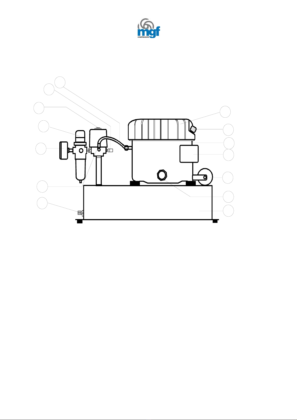
DESCRIZIONE FUNZIONAMENTO COMPRESSORE UNITA’ HELPADENT .................................................. 4
MANUTENZIONE DEL COMPRESSORE.............................................................................................................. 5
DIMENSIONI E CARATTERISTICHE TECNICHE ............................................................................................... 5
Capacità serbatoio....................................................................................................................................................... 5
Aria aspirata................................................................................................................................................................ 5
Pressione massima di funzionamento ......................................................................................................................... 5
Potenza installata ........................................................................................................................................................ 5
Misure di ingombro .................................................................................................................................................... 5
Peso............................................................................................................................................................................. 5
SCHEMA DI FLUSSO UNITA’ HELPADENT........................................................................................................ 6
ATTENZIONE ........................................................................................................................................................... 6
REGOLATORE A PEDALE...................................................................................................................................... 7
MANUTENZIONE SISTEMA ABLATORI ............................................................................................................. 8
ENGLISH VERSION................................................................................................................................................... 10
CEE DIRECTIVES COMPLIANCE........................................................................................................................ 10
GENERAL CHECK ................................................................................................................................................. 10
WARRANTY ........................................................................................................................................................... 10
WERE TO INSTALL HELPADENT UNIT ............................................................................................................ 10
HELPADENT UNIT COMPRESSOR WORKING DESCRIPTION ...................................................................... 12
COMPRESSOR MAINTENANCE.......................................................................................................................... 12
TECHNICAL FEATURES....................................................................................................................................... 12
Air receiver ............................................................................................................................................................... 12
Air inspired ............................................................................................................................................................... 12
Max. pressure working ............................................................................................................................................. 12
Installed power.......................................................................................................................................................... 12
Dimensions ............................................................................................................................................................... 12
Weight ...................................................................................................................................................................... 12
HELPADENT UNIT SYSTEM DIAGRAM............................................................................................................ 13
ATTENTION............................................................................................................................................................ 13
HELPADENT UNITS CONTROL FUNCTIONS ................................................................................................... 14
FOOT CONTROL .................................................................................................................................................... 14
WATER LINE MAINTENANCE............................................................................................................................ 15
2

CONFORMITA’ ALLE DIRETTIVE CEE
L’unità HELPADENT trattata nel presente manuale di istruzione d’uso e manutenzione è costituita
in conformità alle direttive CEE indicate di seguito:
89/392 CEE
89/336 CEE
91/368 CEE
93/44 CEE
93/68 CEE
CONTROLLO GENERALE
Dopo aver estratto dall’imballo l’unità HELPADENT, assicurarsi che non vi siano danni visibili; in
tal caso rivolgersi immediatamente al trasportatore.
Controllare il corredo dei documenti che dovranno comprendere:
Manuale di istruzione e di manutenzione
Dichiarazione di conformità alle norme CEE
Certificato di collaudo
Certificato di garanzia
GARANZIA
La MGF S.r.l. garantisce il buon funzionamento dell’unità HELPADENT per la durata di mesi
dodici (12) a far data del documento di trasporto. Entro i termini suddetti MGF si impegna a
sostituire e riparare gratuitamente le parti che, a giudizio insindacabile del servizio tecnico,
presentano vizi di fabbricazione o di materiale.
Per gli altri dettagli leggere attentamente il certificato di garanzia.
DOVE INSTALLARE L’UNITA’ HELPADENT
Il locale per l’installazione dell’unità HELPADENT deve essere ampio, ben ventilato ed al riparo
da gelo e polvere; l’ambiente polveroso comporterà nel tempo anomalie e difficoltà nel
funzionamento. Pertanto è necessario tenere pulita la macchina nonché lo spazio ad essa circostante
il quale deve essere ampio a sufficienza per favorire sia gli interventi di manutenzione che per
garantire un adeguato flusso d’aria.
3

COMPOSIZIONE COMPRESSORE
1
4
3
2
5
6
7
8
9
10
11
12
13
14
Descrizione componenti:
1) Coperchio alettato in alluminio
2) Tappo olio / Filtro aspirazione
3) Motocompressore da 0,5 Hp
4) Morsettiera
5) Condensatore
6) Spia livello olio da ½”
7) Serbatoio aria da 4 Lt
8) Rubinetto di scarico condensa
9) Manometro d.40 1/8”
10) Filtro regolatore
11) Pressostato
12) Valvola di sicurezza
13) Tubo flessibile di mandata aria
14) Valvola di non ritorno
DESCRIZIONE FUNZIONAMENTO COMPRESSORE UNITA’ HELPADENT
4

Prima di tutto assicurarsi che l’unità HELPADENT sia posizionata su un pavimento in piano per
evitare che essa abbia dei movimenti anomali.
Verificare che il voltaggio corrisponda a quello stampato sull’etichetta identificativa al lato del
compressore.
Assicurarsi che l’interruttore montato sul pressostato sia posizionato su off, quindi collegare
l’apparecchio alla rete elettrica ed avviare il compressore.
Attendere che il compressore compia un ciclo di carica del serbatoio.
Accertarsi che la pressione di uscita dal compressore sia di circa 6 BAR/80 psi; eventualmente
regolarla tramite il filtro regolatore roteando la manopola del filtro in senso orario per aumentare la
pressione ed in senso antiorario per diminuirla così come segnalato sulla stessa ed indicato dal
manometro.
Se durante l’utilizzo dell’unità HELPADENT il compressore continua a pompare è possibile che vi
sia un eccessivo consumo di aria rispetto a quanto non ne riesca a produrre il compressore stesso.
MANUTENZIONE DEL COMPRESSORE
Controllare periodicamente il gruppo compressore. Verificare il livello dell’olio tramite l’apposita
spia posta sul corpo del motocompressore, all’occorrenza rabboccare il livello aggiungendo olio
dopo aver svitato il tappo/filtro aria posto sulla parte superiore del motocompressore fino ad
arrivare a metà spia.
Scaricare giornalmente la condensa accumulatasi all’interno del filtro regolatore dell’aria in uscita
premendo verso l’alto la valvola ad esso sottostante. Espellere sempre dal serbatoio l’aria svitando
il rubinetto di scarico condensa posizionato su una delle estremità del serbatoio; ciò per consentire
la fuoriuscita di eventuale condensa dal serbatoio stesso.
DIMENSIONI E CARATTERISTICHE TECNICHE
Capacità serbatoio 4 Lt
Aria aspirata 50 Lt/min
Pressione massima di funzionamento 8 BAR – 108 psi
Potenza installata 0,5 Hp – 0,37 W
Misure di ingombro L 460 x H 440 x P 320
Peso 29 Kg
5

SCHEMA DI FLUSSO UNITA’ HELPADENT
ACQUA IN PRESSIONE AGLI STRUMENTI
3 VIE ON/OFF
ARIA IN INGRESSO
6 BAR - 80 psi
ARIA REGOLATA
TESTA PRESSURIZZATA
A 2,2 BAR - 30 psi
BOTTIGLIA
TUBO PASSAGGIO
L’aria prodotta dal compressore a 6 BAR – 80 psi viene introdotta al mini regolatore in figura dal
quale esce alla pressione di circa 2,2 BAR – 30 psi. Prima del suo accesso alla bottiglia viene
confluita nel selettore a tre vie; in uscita alla bottiglia vi sarà l’acqua e/o l’aria in pressione destinata
agli strumenti (ablatori e siringa).
ATTENZIONE
Al fine di individuare eventuali danneggiamenti sulle bottiglie è opportuno controllare il loro stato
prima di utilizzare l’unità HELPADENT; se queste dovessero apparire tali si deve provvedere alla
loro immediata sostituzione.
Le bottiglie non devono mai essere lavate in lavastoviglie e la pressione al loro interno non deve
mai superare i 3 BAR – 40 psi.
6

FUNZIONI DI CONTROLLO UNITA’ HELPADENT
Tutte le regolazioni della strumentazione MT520
FIG. A
1
2
3
4
5
sono collocate sulle parti frontali e laterali.
La figura A mostra la collocazione ed identifica
la funzione delle seguenti regolazioni
1-Indicatore di pressione aria
Indica la pressione dell’aria in uscita agli ablatori
2-Selettore strumento
Si usa per selezionare gli ablatori 1 o 2.
Posizionare il selettore sull’ablatore desiderato
(acqua-aria o solo aria)
3-Acqua refrigerante on/off
Attiva il sistema di refrigerazione dell’ablatore.
Posizionando il selettore verso l’alto si attiva il sistema.
4-Regolazione del flusso di acqua refrigerante
Permette le regolazioni siano fatte sugli ablatori.
Ruotando la manopola in senso antiorario si aumenta
Il flusso, in senso antiorario lo si riduce.
FIG. B
6
7
8
9
5-Regolazione pressione dell’acqua
Consente la regolazione agli ablatori secondo la
pressione raccomandata dalla casa produttrice.
Ruotare la vite in senso antiorario per aumentare la pressione
ed in senso orario per diminuirla.
La figura B mostra il gruppo di supporto per gli ablatori e
La siringa
6-Supporto
7- Siringa
8-Ablatore aria-acqua
9 Ablatore solo aria
Gli ablatori aria-acqua e solo acqua sono equipaggiati con una connessione di tipo MID WEST
REGOLATORE A PEDALE
In dotazione all’unità HELPADENT vi è un comando di pressione a pedale il quale permette di
regolare la pressione di lavoro sugli ablatori agendo con il piede sul disco regolatore.
7

MANUTENZIONE SISTEMA ABLATORI
Giornaliera
E’ opportuno, ogni qualvolta si conclude l’utilizzo giornaliero dell’unità HELPADENT, scaricare
completamente la linea di passaggio acqua-aria.
Per fare ciò è sufficiente, dopo aver depressurizzato il sistema avendo preventivamente scollegato
l’unità dalla presa di alimentazione, inserire nell’unità una bottiglia asciutta, riattivare il
compressore alimentandolo, aspettare che il sistema si pressurizzi e quindi far defluire l’aria
attraverso i passaggi dell’acqua della siringa e dell’ablatore acqua-aria fino a quando da essi non
fuoriesca solo aria.
Disattivare nuovamente il compressore scollegandolo dalla presa di corrente e quindi
depressurizzare il sistema completo.
Settimanale
Effettuare le operazioni sopra descritte anche ogni settimana o prima di un lungo periodo di
inutilizzo dell’unità HELPADENT aggiungendo in una soluzione d’acqua delle sostanze
disinfettanti nella bottiglia. Prestare attenzione e fare sempre riferimento alle indicazioni del
produttore del disinfettante.
Attenzione
L’utilizzo di alcuni prodotti per la pulizia e la disinfezione potrebbe creare danni o compromettere il
corretto funzionamento degli strumenti dentali (siringa ed ablatori). La garanzia MGF non copre
eventuali danni che possano scaturire da un utilizzo errato di questi prodotti.
8

LISTA RICAMBI
Pos. Descrizione Codice
1 Coperchio alettato in alluminio 7301
2 Tappo olio - filtro aspirazione 4251
3 Motocompressore da 0,5 Hp 7302
4 Morsettiera completa 7540
5 Condensatore 7528
6 Spia livello olio da 1/2" 8017
7 Assieme châssis - serbatoio aria da 4Lt 7632
8 Rubinetto scarico condensa 5079
9 Manometro d. 40 1/8" attacco radiale 8088
10 Filtro regolatore da 1/4" 4200
11 Pressostato 3/4 vie da 1/4" 8048
12 Valvola di sicurezza da 1/4" 8020
13 Tubo flessibile raccordato MF 1/8"x1/4" 6015
14 Valvola unidirezionale FF1/8" 5263
Raccordo a L maschio a calzamento 1/8" 5274
Raccordo dritto maschio a calzamento 1/8" 8575
Sistema siringhe, bottiglie Forest Med. 8107
9

ENGLISH VERSION
CEE DIRECTIVES COMPLIANCE
The HELPADENT unit described in this instructions and maintenance manual is manufactured in
compliance with the following EC directives:
89/392 CEE
89/336 CEE
91/368 CEE
93/44 CEE
93/68 CEE
GENERAL CHECK
Remove the HELPADENT unit from the package, check that there are no evident signs or damage;
immediately notify to the carrier if they should be present.
Check the documents enclosed:
Use and maintenance instruction manual
EC declaration of conformity
Testing certificate
Warranty certificate
WARRANTY
The correct performance of the HELPADENT unit is guaranteed by MGF S.r.l. for a period of 12
(Twelve) months starting from the delivery notes.
During this period MGF commits itself to replace or repair any parts that on MGF service
department opinion should be damaged by faulty material or bad workmanship free of charge.
WERE TO INSTALL HELPADENT UNIT
The room to install the HELPADENT unit has to be large, well ventilated, fresh, protect against
dust and froze; a dusty room will cause compressor bad working and damges.
It is necessary to keep cleaned the machine and the installation location even to avoid excessive
operation and maintenance costs.
10

COMPRESSOR COMPOSITION
1
4
3
2
5
6
7
8
9
10
11
12
13
14
Components description:
15) Aluminium cap
16) Oil plug / Aspiration filter
17) 0,5 Hp motor- compressor
18) Electric terminal board
19) Condenser
20) ½” Oil level window
21) 4 Lt air receiver
22) Water relief
23) D.40 1/8” pressure gauge
24) Pressure reducer filter
25) Pressure switch
26) Safety valve
27) Delivery air tube
28) Non return valve
11

HELPADENT UNIT COMPRESSOR WORKING DESCRIPTION
Firstly ensure the HELPADENT unit is on level ground. Do not allow it to run if it is standing on an
incline.
Check also that mains voltage corresponds with that shown on the data label on the side of the
compressors.
Ensure that on/off switch mounted on the pressure switch is turned to off position, then plug in the
unit and switch on.
Wait the compressor make an entire air receiver cycle.
Ensure that compressor outlet pressure is 6 BAR – 80 psi as displayed by outlet pressure gauge. If It
is necessary it is possible to adjust by setting the pressure regulator.
To do this lift the pressure regulator knob, and turn clockwise to increase pressure, anticlockwise to
decrease.
If during the HELPADENT unit use the compressor pumps continuously without cutting out
probably there is an excessive air use. Do not exceed the duty cycle for the machine.
COMPRESSOR MAINTENANCE
Check periodically the compressor in HELPADENT unit. Check the oil level by oil level window
and top up if necessary removing the oil filler plug and inject oil inside until the oil level is midway
on oil sight glass.
Drain any condense that may have accumulated in the air outlet filter regulator by pushing the valve
upwards.
When you have finished to use HELPADENT unit always open the drain valve to expel all air and
to allow any condense to drain off.
TECHNICAL FEATURES
Air receiver 4 Lt
Air inspired 50 Lt/min
Max. pressure working 8 BAR – 108 psi
Installed power 0,5 Hp – 0,37 W
Dimensions W 460 x H 440 x D 320
Weight 29 Kg
12

HELPADENT UNIT SYSTEM DIAGRAM
W
ATER TO SYRINGE AND HANDPIECE
3 WAYON/OFF
INCOMNG AIR
6 BAR - 80 psi
REGULATED AIR
PRESSURE HEAD
2,2 BAR - 30 psi
W
ATER
BOTTLE
PICK UP TUBE
The air delivered by compressor at 6 BAR – 80 psi get in to the system small regulator to get out it
at about 2,2 BAR – 30 psi. Before it goes inside the bottle it pass by the tree way selector.
The bottle output will be water and air in pressure to the instruments (syringe and handpiece).
ATTENTION
When using self contained water systems, the plastic bottles should always be inspected for damage
prior to their use. If a bottle appears to be damaged in any manner it should be replaced.
Bottles should never be cleaned in dishwasher . The air pressure to the bottle should not exceed 40
psi.
13

HELPADENT UNITS CONTROL FUNCTIONS
All controls on the MT520 Wall Mount Manual
Handpiece Control are located on the side and front
panels. Figure A shows the location and identifies the
FIG. A
1
2
3
4
5
function of these controls.
1-Drive air pressure gauge
Indicates drive air pressure to the handpiece
2-Handpiece selector
Used to select handpiece 1 or handpiece 2.
Flip the toggle towards to appropriate number
3-Water coolant on/off
Activates handpiece water coolant system.
Flip the toggle up to activate the system.
4-Water coolant flow control
Allow adjustments to be made to the handpieces.
Turn the knob counter clockwise to increase the flow,
anticlockwise to decrease to reduce.
FIG. B
6
7
8
9
5-Drive air pressure control
Allows handpieces to be adjusted to its manufacturer’s
recommended operating pressure.
Turn the adjusting screw counter clockwise to increase the
Flow, anticlockwise to decrease.
Figure B shows the manual handpiece holder and
Syringe holder assembly.
6-Holder
7- Syringe
8-Handpiece 1
9 Handpiece 2
Both handpiece 1 and 2 are equipped with Mid-west connection.
FOOT CONTROL
Regulates drive air and water to the active handpiece. To operate apply pressure to the foot control
for drive air.
14

WATER LINE MAINTENANCE
Daily
The most convenient way to maintain water lines in your HELPADENT unit is to use an empty and
dry bottle after you disconnect the unit from the power in and let the unit unpressured.
Connect the unit to the power input and wait for the unit reaching the working pressure (6 BAR- 80
psi).
Let pass dry air inside the water line till when from the syringe and the handpiece get out only air.
Once done that disconnect the HELPADENT unit from the power in and let all the unit
unpressuring.
Ensure that in the water line there is not a stagnation of fluids.
Weekly
Make this operations as described below every week or before a long time of no making use of
HELPADENT unit adding a solution of water and disinfectant agent according to manufacturers
recommendations to a disinfectant bottle.
Caution
Use of certain cleaning or disinfecting agents may cause damage to or affect the performance of the
dental equipment water system. MGF warranty does not cover damages to equipment resulting from
the use of such agent. Always follow the agents manufacturers agent.
15

SPARE PARTS LIST
Pos. Description Code
1 Aluminium cap 7301
2 Oil plug – Aspiration filter 4251
3 0,5 Hp Pump-motor 7302
4 Electric connection terminal 7540
5 Condenser 7528
6 1/2" Oil level window 8017
7 Compressor chassis - 4Lt air receiver 7632
8 ¼” Drain cock 5079
9 D. 40 1/8" radial fitted 8088
10 1/4" Regulator filter 4200
11 1/4" 4 way pressure switch 8048
12 1/4" safety valve 8020
13 MF 1/8"x1/4" delivery pipe 6015
14 FF 1/8" Non return valve 5263
1/8" M elbowed fitting for tygon tube 5274
1/8" M fitting for tygon tube 8575
Water line Forest Med. system 8107
16
Table of contents
Languages:
Other MGF Air Compressor manuals