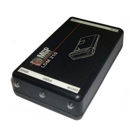
MGP Instruments DRM-1 Use and care manual

OPERATION & CALIBRATION MANUAL
DRM Family of
Wireless Data Radiation Monitors
DRM-1, DRM-1D, DRM-2, DRM-2D
Document # 15-00044
Revision 5
April 2008

15-00044
Revision 5
April 2008
The publication, translation or reproduction, either party or wholly, of this document are not allowed without our written consent. 2
Revision Log
Revision #
Date
Revised
Pages
Comments
0
1
2
3
4
5
July 2004
March 2005
May 2005
October 2006
July 2007
April 2008
N/A
ALL
6,11-13, and
30
15
All
ALL
Original issue.
Added DRM-1D information, specifications, calibration, FCC
information about WRM2, instructions on using RMV
software (removed AMPView), and section for optional
display unit and corrected typographic errors (formatting).
Changed title.
Added outline drawings for the DRM-1/D and information
about the automatic background subtraction feature for the
DRM-1D
Added note about dipswitch settings for field use and
calibration, section 3.22
Better description of DRM-1D calibration, Section 9.1
Various editing throughout manual
Inclusion of DRM-2/2D, Power Saving Mode update,
Environmental & Solar Enclosure configurations, minor
editing through-out.
Added new features with firmware 071111 for DRM-1 and
DRM-2 for 4 threshold settings and selectable using the
‘ACK’ button on the DRM-1 display or DRM-2. Added new
screen shots of RMV for threshold settings and instructions

15-00044
Revision 5
April 2008
The publication, translation or reproduction, either party or wholly, of this document are not allowed without our written consent. 3
WRM-2 FCC COMPLIANCE
ANTENNA WARNING
FCC QUALIFICATIONS
Important: The WRM2 radio modules have been certified by the FCC for integration
into OEM products without any further certifications (as per FCC section
2.1091). Changes not expressly approved by MGP Instruments could void
the user’s authority to operate this equipment.
Note: The WRM2 System utilizes a proprietary communication (WRM) protocol
and specific firmware identification for each component and is configured
for optimal performance.
Operation of the WRM2 system in a configuration not consistent with MGPI
settings, or modifications to hardware and firmware may result in degraded
system performance and loss of warranty.
CAUTION: Only the power supplies and batteries specified by MGPI should be used
with all DRM components. Non-approved power sources can result in
component damage or personal injury. Contact MGPI for additional
information!
This device complies with Part 15 of the FCC rules. Operation is subject to
the following conditions: (1) this device may not cause harmful interference and (2) this
device must accept any interference received, including interference that may cause
undesired operation, FCC ID Number: ‘our9xstream’.
This device has been tested with Reverse Polarity SMA and MMCX
connectors with the antennas that are supplied with the equipment. When integrated in the
OEM product, these fixed antennas require installation preventing end users from replacing
them with non-approved antennas. Any antennas not supplied by MGP Instruments must
be tested to comply with FCC Section 15.203 for unique antenna connectors and section
15 emissions.

15-00044
Revision 5
April 2008
The publication, translation or reproduction, either party or wholly, of this document are not allowed without our written consent. 4
Table of Contents
1. DRM-1/2 and DRM 1D ...................................................................................................................6
1.1. General Description...........................................................................................................................6
1.2 Applications for GM Tube (DRM-1, DRM-2) and CsI (DRM-1D) Detectors............................7
2. DRM-1 Specifications......................................................................................................................8
2.1 General DRM-1 (GM Tube) .............................................................................................................8
2.2 DRM-1D/2D Cesium Iodine (Tl) Specifications ..............................................................................9
2.3 DRM-2 Specifications.....................................................................................................................10
2.4 DRM Outline Drawings ..................................................................................................................12
2.5 DRM-1D Outline Drawings ............................................................................................................15
2.6 Over The Air Communications .......................................................................................................16
2.7 Response Times for the GM Tubes.................................................................................................16
2.8 DRM-1/2D Response Times for the CsI (Tl) Detector ...................................................................16
3. Operating Instructions ..................................................................................................................17
3.1 Preparation for Use..........................................................................................................................17
3.2 Starting-Up......................................................................................................................................17
3.3 Meter Connectors ............................................................................................................................18
3.4 Power Supply & Battery..................................................................................................................19
4. General Functions..........................................................................................................................20
4.1 Dipswitch Selector ..........................................................................................................................20
4.2 Dipswitch Positions.........................................................................................................................20
4.3 DRM-2 and Optional External Display & Alarm ...........................................................................26
4.4 Battery Replacement .......................................................................................................................27
5. Communication..............................................................................................................................28
5.1 Communication ...............................................................................................................................28
5.2 Protocol ...........................................................................................................................................28
6. Communication Protocol ..............................................................................................................28
6.1 Set Meter Parameter Via the PC .....................................................................................................30
7. Setting Meter Parameters Using the RMV Software .................................................................32
8. Calibration Summary For The DRM-1/2....................................................................................35
8.1 Preface.............................................................................................................................................35
9. Calibration Summary For The DRM-1D/2D ..............................................................................36
9.1 Preface.............................................................................................................................................36

15-00044
Revision 5
April 2008
The publication, translation or reproduction, either party or wholly, of this document are not allowed without our written consent. 5
10. Calibration Procedure for the DRM-1D/2D................................................................................37
10.1 Preface.............................................................................................................................................37
10.2 Operating Instructions .....................................................................................................................37
10.3 Template and Parameters ................................................................................................................37
10.4 Starting Up the Calibration and Linearity Process ..........................................................................39
10.5 Calibration.......................................................................................................................................40
10.6 Linearity ..........................................................................................................................................42
10.7 Save, Load and Print Calibration and Linearity Certificate ............................................................44
10.8 DRM-1/2 cps To Mr/H Conversion Table ......................................................................................45
10.9 DRM-1D cps To Mr/H Conversion Table ....................................................................................465
11. Upgrading the DRM Firmware ....................................................................................................47
12. DRM - List Of Electronic Schematics..........................................................................................51
13. DRM - Environmental Enclosure Configuration .......................................................................55
14. DRM Solar Configuration ............................................................................................................57

15-00044
Revision 5
April 2008
The publication, translation or reproduction, either party or wholly, of this document are not allowed without our written consent. 6
1. DRM-1/2 and DRM-1D
1.1. General Description
The Data Radiation Monitor - DRM-1/2, is an auto switching two GM-tube based dose rate meter and the DRM-
1D is a sensitive CsI (Tl) scintillated coupled to a PMT. The DRM-1/2 are dose rate meters for detection, using
state-of-the-art microprocessor-based technology and combined with telemetry using the WRM2 900 MHz or 2.4
GHZ FHSS radio. The DRM is designed for highly stable and accurate dose rate measurements from gamma
radiation. The DRM-1/2 (GM) measuring range is from 0.05 mR/h up to 1000 R/h and the DRM-1D’s measuring
range is from 0.001 mR/h up to 10 mR/h.
The DRM is a lightweight and compact instrument with sophisticated software offering special features and
optimal performance for telemetry data. The wide dynamic range is obtained by the DRM-1’s two GM-Tubes
with automatic range switching and an automatic dead time correction, according to the preset calibration. The
DRM-1D’s sensitive range is obtained by CsI(Tl) scintillator (30*30mm) coupled to PMT and an automatic dead
time correction and back ground subtraction, according to the preset calibration. A special averaging function
smoothes the data reading and maintains fast response time, while keeping the standard deviation at a minimum
for both DRM-1/2 and DRM-1/2D
Software is used to configure (RMV) and calibrate (RMC) the DRM family of detectors.
An automatic self-diagnostic procedure continuously checks both electronics and detectors and reports any case
of detector failure.
The DRM may be used in the following ways:
•by connecting the meter to a PC
•by connecting the meter to a DDC-16/AM-16 Area Monitor (wired)
•by using the internal WRM2 FHSS radio to transmit data
•by connecting the meter to an external WRM transmitter (wireless)
•by using an internal or externally connected network adapter
The meter includes four boards: HV board, CPU board, WRM2 radio and the board for the dual GM-Tube
detectors or a cesium iodine detector. A built-in RS-232 is the connection used for calibration and configuration.
A custom connector is needed when using the WRM external transmitter. The WRM2 FHSS radio is already
included in the DRM-1/2 package and a base station (MGPI P/N: WR2-9001) is needed for reception of
telemetry data. A second DB-9 female connector is available for an optional alarm and display unit for the
DRM-1/1D.

15-00044
Revision 5
April 2008
The publication, translation or reproduction, either party or wholly, of this document are not allowed without our written consent. 7
1.2 Applications for GM-Tube (DRM-1, DRM-2) and CsI (DRM-
1D) Detectors
Perimeter & Boundary Surveillance
Vehicle Access Points
Turnstile entries
Collection of Survey Data for Real-time Mapping & Surveillance Software
General Area Monitoring
Hospital Emergency Room Entrances and CBRNE storage areas
Response vehicles
Event Monitoring

15-00044
Revision 5
April 2008
The publication, translation or reproduction, either party or wholly, of this document are not allowed without our written consent. 8
2. DRM Specifications
2.1 DRM-1 General (GM Tube)
•Detector
GM tube ZP-1301 (or equivalent) - high range
GM tube ZP-1201 (or equivalent) - low range
Optional GM tube ZP-1300 non-energy compensated – low range
Optional CsI (Tl) detector
•Measuring Ranges :
0.05 mR/h to 1000 R/h (0.5 µSv/h to 10 Sv/h)
Automatic switching between the two GM tubes at
600mR/h and 800mR/h
•Accuracy
±10 % of reading, within the measuring range
•Energy Response (137Cs)
±20 % at 70 keV to 2 MeV
•Sensitivity (137Cs):
17 cps/mR/h (low range)
0.3 cps/mR/h (high range)
•Power Source
External power supply and battery backup
External power supply: Input 120-250 Vac, Output 6 Vdc to 15 Vdc with locking connector
Battery back-up: Three (3) 1.2v NiMH 2100mA rechargeable
Battery operating lifetime: Up to 12 hours of continuous operation
Power Saving Mode On/Off using Meter View Software
•Temperature Range
Operation: -10°C to +50°C (15°F to 122°F)
Storage: -20°C to + 60°C (-5°F to 140°F)
•Humidity Range
10% to 95% RH (non condensing)
Enclosure MaterialAluminum
•Dimensions
Width: 108 mm (4.25”)
Length: 178 mm (7”)
Height: 64 mm (2.5”)
Weight:: 907 gr. (2 lbs)

15-00044
Revision 5
April 2008
The publication, translation or reproduction, either party or wholly, of this document are not allowed without our written consent. 9
•Optional Accessories
Remote Display Unit (external visual & audible alarm)
Magnet attachments
2.2 DRM-1D/2D Cesium Iodine (TL) Specifications
•Detector:
CsI (Tl) (30 x 30 mm) crystal optically coupled to PMT with 0.5 mm aluminum housing and
solid mu metal shield. With optional automatic background subtraction using the RMV
software.
•Measuring Range
1uR/h to 9999 uR/h (0.001 mR/h to 9.999 mR/h)
Overflow Alarm for reading > 9999 uR/h
Overload for field > 1 R/h
Sensitivity: 6.8 cps/uR/h for 137-Cs
Optional : background subtraction via the RMV software
•Display range
0.01 mR/h to 10,000 mR/h
•Dimensions
DRM-1D: 7" L x 3.5" D x 4.25" W
DRM-2D: 10.25” L x 4.28” D x 4.88 W
•Display – LCD Readout:
4digits for accurate and easy display
Detector failure
Low battery
Overflow
4 Threshold Settings
•Audio:
Two internally mounted piezo-electric elements (used for alarm functions)
•Accuracy (137Cs)
±10 % of reading, within the measuring range
•Energy Response
45 KeV to 2 MeV
•CsI Sensitivity (137Cs):
6.8 cps/µR/h

15-00044
Revision 5
April 2008
The publication, translation or reproduction, either party or wholly, of this document are not allowed without our written consent. 10
•Power source
External power supply and battery backup
External power supply: Input 120-250 Vac, Output 9 to 15 Vdc with locking connector
Battery back-up: Three (3) 1.2v NiMH 2100mA rechargeable
Battery operating lifetime: Up to 8 hours of continuous operation (with optional Alarm and
Display Unit: 4 hours)
Power Saving Mode On/Off using Meter View Software
•Temperature Range
Operation: -10°C to +50°C (15°F to 122°F)
Storage: -20°C to + 60°C (-5°F to 140°F)
•Humidity Range
10% to 95% RH (non condensing)
Enclosure Material Aluminum
2.3 DRM-2 Specifications
•Detector
GM tube ZP-1301 (or equivalent) - high range
GM tube ZP-1201 (or equivalent) - low range
Optional GM tube ZP-1300 non-energy compensated – low range
Optional CsI (Tl) detector
•Measuring Ranges :
0.05 mR/h to 1000 R/h (0.5 µSv/h to 10 Sv/h)
Automatic switching between the two GM tubes at
600mR/h and 800mR/h
•Display Range:
0.01 mrem/hr to 10,000 mrem/hr
•Accuracy
±10 % of reading, within the measuring range
•Energy Response (137Cs)
±20 % at 70 keV to 2 MeV
•Sensitivity (137Cs):
17 cps/mR/h (low range)
0.3 cps/mR/h (high range)
•Power Source
External power supply and battery backup
External power supply: Input 120-250 Vac, Output 6 Vdc to 15 Vdc with locking connector

15-00044
Revision 5
April 2008
The publication, translation or reproduction, either party or wholly, of this document are not allowed without our written consent. 11
Battery back-up: Three (3) 1.2v NiMH 2100mA rechargeable
Battery operating lifetime: Up to 12 hours of continuous operation
Power Saving Mode On/Off using Meter View Software
•Display – LCD Readout:
4digits for accurate and easy display
Detector failure
Low battery
Overflow
4 Threshold Settings
•Audio:
Two internally mounted piezo-electric elements (used for alarm functions)
•Measurement Units:
mrem/hr
•Controls:
Alarm Acknowledgment push-button
DIP Switches for functionality
•Temperature Range
Operation: -10°C to +50°C (15°F to 122°F)
Storage: -20°C to + 60°C (-5°F to 140°F)
•Humidity Range
10% to 95% RH (non condensing)
Enclosure MaterialAluminum
•Dimensions
10.25” L x 4.28” D x 4.88 W

15-00044
Revision 5
April 2008
The publication, translation or reproduction, either party or wholly, of this document are not allowed without our written consent. 12
2.4 DRM Outline Drawings

15-00044
Revision 5
April 2008
The publication, translation or reproduction, either party or wholly, of this document are not allowed without our written consent. 13
2.4 DRM Outline Drawings (continued)

15-00044
Revision 5
April 2008
The publication, translation or reproduction, either party or wholly, of this document are not allowed without our written consent. 14
2.4 DRM Outline Drawings (continued)
DRM-1 Inside View

15-00044
Revision 5
April 2008
The publication, translation or reproduction, either party or wholly, of this document are not allowed without our written consent. 15
2.5 DRM-1D Outline Drawings
DRM-1D Inside View

15-00044
Revision 5
April 2008
The publication, translation or reproduction, either party or wholly, of this document are not allowed without our written consent. 16
2.6 Over the Air Communications
900 MHz or 2.4 GHz FHSS (Frequency Hopping Spread Spectrum) Radios with External Antenna (WRM2
system) – Base receiver required for use with WRM2 or WRM91, EXT-2000 External Transmitters and WRM-
Plus receiver.
2.7 Response Times for the GM Tubes
Table 1
Response Time for Small Changes
Table 2
Fast Response Time
Radiation Field
Range
[mR/h]
Response
Time
[sec.]
Radiation field
[mR/h] from
to/above
Response
Time
[sec.]
< 0.5 45 0.05 1.0 ≤2
0.5 - 1.5
30 0.5 3.0 ≤2
1.5 - 2.5 20 1.5 5.0 ≤2
2.5 - 6 10 2.5 12 ≤2
6 - 12 6 6 20 ≤2
12 - 24 4 12 40 ≤2
20 - 60 3 20 60 ≤2
60 - 800 2 1 R/h 2 R/h ≤2
0.6 - 1.2 R/h 5 2 R/h 2.6 R/h ≤2
1.2 - 2 R/h 4
2 - 3 R/h 3
3 - 10 R/h 2 – 3
> 10 R/h ≤2
If the radiation field measured by the meter increases significantly, the response time will be ≤2 sec. as seen in
Table 2. In other cases the response time is according to Table 1.
For example:
•For a radiation field increase from 2.5 mR/h to 12 mR/h, the response time will be ≤2 sec.
•For radiation field fluctuations between 2.5 mR/h and 6 mR/h, the response time will be 10 sec.
2.8 DRM-1/2D Response Times for the CsI (TL) Detector
The instrument’s response time is less then 2 seconds once the radiation intensity at the reference point increases
or decreases by a factor of 10. e.g 0.001 to 0.01 mR/h (1µR/h to 10µR/h).

15-00044
Revision 5
April 2008
The publication, translation or reproduction, either party or wholly, of this document are not allowed without our written consent. 17
3. Operating Instructions
3.1 Preparation for Use
Remove the instrument from the shipping container and check for any physical damage. In the case of damage,
report it to the carrier and contact MGP Instruments.
Caution: Do not attempt to install or operate damaged equipment since safety and
performance may be affected.
3.2 Starting-up
3.2.1 Connect the antenna to the WRM2 PRSMA connector located on the top of the enclosure. The
antenna is only needed when transmitting data over-the- air.
3.2.2 Switch dipswitch 3, for data output from the WRM2 radio, to the ON position or dipswitch 5 &
6 to the ON position when programming the internal WRM2 radio See “Wireless Remote
Monitoring Operating Manual”, 15-00043 for configuring the WRM2 radio.
Note: Ensure dipswitches 1,2,3,7 and 8 are in the ON position when deploying
the unit for field use. Dipswitch 4 must be in the OFF position at on times
for field use and calibration.
3.2.3 Switch dipswitch 7&8 to the ON position to engage the battery backup
3.2.4 Connect the external power supply to the locking miniature power supply connector
3.2.5 Connect external WRM transmitter if used and ensure that the baud rate for the DRM and the
WRM External Transmitter are set to 300 bps. The interval level for the DRM needs to be set to
ZERO (0), using RMV, so that the WRM transmitter can request the data from the device.
Note: By engaging the battery or the external power supply, the meter will start
operating. The unit is not supplied with an On-Off switch.
3.2.6 NOTE: (Firmware >= 071111 (MARCH 2008) and board updates) By pressing the ‘ACK
‘button once on the DRM-1 external display or the DRM-2 will show the current threshold rate
setting, thr.0 then the rate setting i.e., 300. By pressing the ACK button a second time and so
forth will show user preset threshold settings that were configured using the RMV software.
See section 4.2.10 for RMV software Dose Rate Threshold settings. See section 4.2.10 for more
information on setup and usage
ACK thr.0 = selected ACK thr.1 ACK thr.2 ACK thr.3 ACK thr.4

15-00044
Revision 5
April 2008
The publication, translation or reproduction, either party or wholly, of this document are not allowed without our written consent. 18
3.3 Meter Connectors
3.3.1 Connectors:
The DRM-1 contains three connectors:
1. 2.5 mm External power supply connector (type L712RA supplied by Switch craft, center post is
positive)
2. D-type 9 pin female for RS232 communication port
3. D-type 9 pin male for remote display & alarm
Ground (
-
)
6 to 15v DC
(+)
1
5
7
2
3
4
9
Ground
/common
Rx
Tx
5v
2
1
2
3
4
5
6
7
8
9
Display data
Display clk
Ready
Alarm
5v
Ground /common
Ext DC
Battery backup
3

15-00044
Revision 5
April 2008
The publication, translation or reproduction, either party or wholly, of this document are not allowed without our written consent. 19
3.3.2 External Connectors:
Meter to PC RS232 Cable
D-type 9 pin female D-type 9 pin male
Meter to External Display & Alarm Unit (lengh 25')
3.4 Power Supply & Battery
•External power supply type CINCON 418-TR1507-12 (15v) with locking plug (type 761K Switchcraft
- center positive)
•Input 120-250 VAC
•Output 15 VDC 1.6A
•The meter can be operated using DC power from 5 volt to 16volt (0.7A)
•The meter is protected in case of reverse polarity
•Battery backup: 3 units of NiMH GP2100 type AA 1.2V, 2100mA
2
3
5
3
2
5
1
2
3
4
5
6
7
8
9
1
2
3
4
5
6
7
8
9
D-type 9 pin female D-type 9 pin female
Display & Alarm Unit Meter

15-00044
Revision 5
April 2008
The publication, translation or reproduction, either party or wholly, of this document are not allowed without our written consent. 20
4. General Functions
4.1 Dipswitch Selector
To set the dipswitch, unscrew two screws located at the meter front panel and remove the dipswitch cover.
The dipswitch (8 switches) is located on the meter’s front panel. Using these dipswitches you can setup two
functions:
a) Communication mode, and;
b) Connect-disconnect the backup batteries.
Dipswitches position: For the ON position, press the dipswitch downward.
The DRM has one UART (Universal Asynchrony Receive Transmit Port) and one communication RS232 port;
the dipswitch position enables a selection of the communication mode
To set the dipswitch, unscrew two screws located at the meter front panel and remove the dipswitch cover.
4.2 Dipswitch Positions
4.2.1 1&2 On
•Connects the DRM UART to the RS232 communication port via the D-type 9 pin female connector
•Enables connection of the meter to PC for meter parameter setting, calibration or download the meter reading
directly to PC, (Using RMV software for configuration and RMC for calibration).
4.2.2 3 On & 4 Off
•Connects the DRM UART to the internal wireless transmitter to send data reading via WRM2. Switch 3 is
for transmitting and Switch 4 is for receiving data.
4.2.3 5&6 On
•Connects the internal wireless transmitter to the RS232 communication port via the D-type 9 pin female
connector. See “Wireless Remote Monitoring 2 Operating manual, 15-00043” for configuring the WRM2
radio.
•Enables the setting of internal wireless transmitter WRM2 parameters.
4.2.4 7&8 On
•Connects the internal three NiMHd rechargeable batteries for back-up power if the external power is
disconnected
Note: If the external power supply is connected, the battery will be charged even
though the dip switches 7&8 are in the OFF position.
This manual suits for next models
3
Table of contents
Other MGP Instruments Measuring Instrument manuals
Popular Measuring Instrument manuals by other brands
Leica Geosystems
Leica Geosystems DISTO E7100i manual
TIMEDOX
TIMEDOX Silver quick start guide
Unitronics electric
Unitronics electric UM2B user manual

Lovibond
Lovibond Tintometer MD100 instruction manual

ABB
ABB AquaMaster 3 user guide
engelmann
engelmann microCLIMA DE-16-MI004-PTB025 Installation and operating instructions
