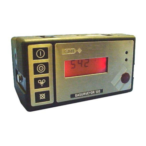
GMI Gasurveyor 6 - 500 Instruction Manual

1
Gasurveyor
6-500 / 6B-500
User Handbook

Issue 5
21/07/10
Part Number: 42278
GMI welcomes comments on all our publications.
Your comments can be of great value in helping us
to improve our customer publications. Please send
any comments that you have to our Sales
Department at GMI. Contact details are provided
inside the back cover of this handbook.
Instrument Service / Repair contact details are also
provided inside the back cover of this handbook.

i
COPYRIGHT
This User Handbook is copyright of Gas Measurement Instruments Ltd (GMI) and
the information contained within, is for use only with the Gasurveyor 6-500 and
6B-500 instruments. Reproduction, in whole or in part, including utilisation in
machines capable of reproduction or retrieval without written permission of Gas
Measurement Instruments Ltd is prohibited. Reverse engineering is not permitted.
LIABILITY
Every care has been taken in the preparation of this document, but GMI Ltd do not
accept any responsibility for errors or omissions and their consequences. Information
in this document is subject to change without notice. This document does not constitute
a specification or basis for a contract. Your statutory rights under law are not affected.
MODIFICATION NOTICES
GMI aim to notify customers of relevant changes in the product operation and maintain
this manual up to date. In view of the policy of continuous product improvement
there may be operational differences between the latest product and this manual.
This Handbook is an important part of the Gasurveyor 6-500 and 6B-500 products.
Please note the following points:
• It should be kept with the instrument for the life of the product.
• Amendments should be attached.
• This Handbook should be passed on to any subsequent owner/user of the
instrument.
• Although every care is taken in the preparation of this Handbook it does not
constitute a specification for the instrument.
SOFTWARE
Software supplied on EPROM or similar device for use in a particular product, may
only be used in that product and may not be copied without the written permission of
Gas Measurement Instruments Ltd. Reproduction or disassembly of such embodied
programmes or algorithms is prohibited. Ownership of such software is not
transferable and GMI Ltd does not warrant that the operation of the software will be
error free or that the software will meet the customer’s requirements.
DISPOSAL ADVICE
When no longer in use, dispose of the instrument carefully and with respect for the
environment. GMI will dispose of the instrument without charge if returned to the
factory.

GASURVEYOR 6-500 / 6B-500 USER HANDBOOK
ii
SAFETY
• The instrument must be regularly serviced and calibrated by fully trained
personnel in a safe area.
•Batteries: Alkaline batteries or *Rechargeable battery pack must be
exchanged (*and recharged) in a safe area and fitted correctly before use.
Never use damaged batteries or expose to extreme heat.
See Section 4 : OPERATOR MAINTENANCE.
• Only GMI replacement parts should be used.
• If the instrument detects gas, follow your own organisation’s procedures and
operational guidelines.
• The combustion chamber is a flameproof assembly and must not be opened
in the presence of a flammable atmosphere.
• Gasurveyor 6-500 / 6B-500 instruments are certified as EEx iad IIC T4
(-20oC<Tamb <50oC). BAS01ATEX2292 II 2 G.
UL Class 1 Groups A, B, C and D.
• This equipment is designed and manufactured to protect against other
hazards as defined in paragraph 1.2.7 of Annex II of the ATEX Directive
94/9/EC
Any right of claim relating to product liability or consequential damage to any third
party against GMI is removed if the warnings are not observed.
AREAS OF USE
Exposure to certain chemicals can result in a loss of sensitivity of the flammable
sensor. Where such environments are known or suspected it is recommended that
more frequent response checks are carried out. The chemical compounds that can
cause loss of sensitivity include Silicones, Lead, Halogens and Sulphur. Do not
use instrument in potentially hazardous atmospheres containing greater than 21%
Oxygen. The enclosure material is polypropylene and must not be exposed to
environments which are liable to result in mechanical or thermal degradation or to
damage caused by contact with aggressive substances. Additional protection may
be required in environments where the instrument enclosure is liable to damage.
STORAGE, HANDLING AND TRANSIT
The batteries in the rechargeable pack contain considerable energy and care should
be taken in their handling and disposal. Battery packs should be removed if the
instrument is stored for longer than 3 months. The instrument is designed to handle
harsh environments. The sensing elements are sealed to IP54 and the rest of the
instrument to IP64. If not subject to misuse or malicious damage, the instrument
will provide many years of reliable service. The instrument contains electrochemical
sensors with a life of 2 years. Under conditions of prolonged storage the sensors
should be removed. The sensor contains potentially corrosive liquid and care should
be taken when handling or disposing of the sensor, particularly when a leak is
suspected.

iii
REVISION RECORD
Date Pages Description Of
Change
Issue 1 All New Handbook
01/06/01
Issue 2 All To update alarm function
31/10/02 and incorporate 6B-500
configuration in
handbook
Issue 3 All To include effect of
17/07/03 CN 2291
Issue 4 All To include Appendix C
20/07/04 (translations)
Issue 5 All To include effect of
21/07/10 CN 4993

GASURVEYOR 6-500 / 6B-500 USER HANDBOOK
iv

v
CONTENTS
COPYRIGHT ................................................................. i
LIABILITY ...................................................................... i
MODIFICATION NOTICES ........................................... i
SOFTWARE .................................................................. i
DISPOSAL ADVICE ...................................................... i
SAFETY ........................................................................ ii
AREAS OF USE ........................................................... ii
STORAGE, HANDLING AND TRANSIT ...................... ii
REVISION RECORD ..................................... iii
INTRODUCTION ........................................... 1
GENERAL INFORMATION ........................... 3
Ranges of Operation .................................................... 3
LEL, 0 to 100% .......................................................... 3
Volume Gas, 0 to 100 % ............................................ 4
Carbon Monoxide 0 – 1000 ppm ............................... 5
PPM Methane 0 – 1000 ppm (6B-500 only) .............. 6
Alarm Functions ......................................................... 7
Construction .................................................................. 8

GASURVEYOR 6-500 / 6B-500 USER HANDBOOK
vi
Batteries ........................................................................ 8
Disposable Alkaline (LR20) Dry Cell Batteries .......... 8
Rechargeable Battery Pack ....................................... 9
Filters ............................................................................ 9
Liquid Crystal Display (LCD) ...................................... 10
Before Use Checks ..................................................... 10
OPERATING INSTRUCTIONS.................... 11
Measure Mode Operation ........................................... 11
Switching On ............................................................ 12
Calibration Date Features ........................................ 13
Switching Off the Instrument Pump ......................... 13
Switching Off ............................................................ 14
Changing Range ...................................................... 14
Zero PPM Methane Range (6B-500 only) ............... 15
Summary of Button Operation ................................. 15
Operator Messages / Fault Flags ............................... 16
OPERATOR MAINTENANCE ..................... 19
Rechargeable Battery Pack ........................................ 19
Standard Charger ..................................................... 19
Flatbed Charger ....................................................... 20
Smart Charger .......................................................... 20
Replacing the Battery Pack ..................................... 21
Recharging the Battery Pack ................................... 22

vii
CONTENTS
Replacing Alkaline (LR20) Dry Cell Batteries ............ 22
Filter Replacement ..................................................... 24
CALIBRATION ............................................ 27
Calibration Validity ...................................................... 28
ACCESSORIES........................................... 29
ADDITIONAL INFORMATION ..................... 33
Training ....................................................................... 33
World Wide Web ......................................................... 33
TYPICAL OPERATING PARAMETERS .....A-1
Size ........................................................................ A-2
Weight .................................................................... A-2
Operating Temperature .......................................... A-2
Humidity ................................................................. A-2
Construction ........................................................... A-2
Display .................................................................... A-2
Sampling System ................................................... A-2
Power Source ......................................................... A-3

GASURVEYOR 6-500 / 6B-500 USER HANDBOOK
viii
FIELD CALIBRATION ................................ B-1
Selectable Ranges in FCM ....................................... B-3
Entering FCM ............................................................ B-3
Zeroing the Instrument ............................................. B-4
Field Calibration Procedure ...................................... B-5
Quitting FCM ............................................................. B-9
Quit And Save Changes ........................................ B-9
Quit Without Saving Changes ................................ B-9
OPERATING INSTRUCTIONS.................. C-1
English ..................................................................... C-2
Deutsch (German) ................................................... C-6
Svensk (Swedish) ................................................. C-10
Dansk (Danish) ...................................................... C-14
Nederlands (Dutch) .............................................. C-18
INDEX ............................................................ I


GASURVEYOR 6-500 / 6B-500 USER HANDBOOK
2
The Gasurveyor 6-500 and 6B-500 contain the following
ranges:
•LEL flammable, 0 to 100%
•Volume Gas flammable, 0 to 100%
•Carbon Monoxide, 0 to 1000 ppm
•Methane, 0 to 1000 ppm (6B-500 only)
As the Gasurveyor 6-500 and 6B-500 have a wide variety
of available user selected options, it is not possible to
provide an operator handbook specific to each possible
variation, therefore, what we have provided in the
following pages is the standard default of how the
instrument would generally be configured, with the
possible options detailed in italic text.
GMI recommend that you take the time to study your
instrument and, where practical and with advice from your
company’s Purchasing / Management departments,
highlight your particular instrument configuration.
The main default features of the instrument are:
$Rugged carbon loaded polypropylene case, sealed
to IP54 rating and suitable for outdoor use.
$Two button operation allowing the user access to
all features.
$LCD with backlighting which displays the current
gas readings (in both digital and analogue forms)
together with operational and status information.
$Directly interfaces with the GMI Auto Test Cali-
bration Units.

3
2
GENERAL INFORMATION
Ranges of Operation
LEL, 0 to 100%
The LEL range indicates the explosibility of the flammable
gas in the sample. This is displayed as a percentage of the
lower explosive limit (LEL) of the gas. For methane 100%
LEL corresponds to 5% Volume methane in Air.
The instrument range is displayed in the top right corner
of the display as % LEL. From 0 to 10% LEL the digital
display resolves to 0.1% LEL. From 10 to 100% LEL the
digital display resolves to 1% LEL. The analogue bar
graph follows in 4% steps. An example of the LEL
displayis shown in Figure 2.1. Autoranging will
automatically switch the range to Volume Gas when 100%
LEL is reached.
The detection principle for this range is a catalytic reaction.
Figure 2.1 LEL Range

GASURVEYOR 6-500 / 6B-500 USER HANDBOOK
4
Volume Gas, 0 to 100 %
This range displays the total volume of a specific
flammable gas with respect to air. The calibration gas is
shown on the service label and for the purpose of this
handbook is assumed to be methane. Instruments
calibrated for methane in air should only be used for
measuring such mixtures. To change the calibration gas,
e.g. from methane to propane, the instrument must be
recalibrated by suitably trained personnel.
On the Volume Gas range the instrument range is
displayed in the top right corner of the LCD as GAS. The
digital display resolves the signal to 1% GAS with the
analogue bar graph following in steps of 4%. Figure 2.2
shows the Volume Gas display. The detection principle
for the Volume Gas range is thermal conductivity.
Figure 2.2 Volume Gas Range

5
GENERAL INFORMATION
Carbon Monoxide 0 – 1000 ppm
This range displays the parts per million (ppm) Carbon
Monoxide content up to 999 ppm. The instrument range
is displayed in the top right hand corner of the display as
CO.
The digital display resolves to 1 ppm CO. The analogue
bar graph follows in 40 ppm steps. Above 1000 ppm,
EEEE is displayed.
The Carbon Monoxide sensor is subject to the effect of
pressure transients and should be operated at normal
atmospheric pressure conditions. The sensor has a normal
operating life of two years.
Figure 2.3 shows a typical Carbon Monoxide display.
Figure 2.3 Carbon Monoxide Range

GASURVEYOR 6-500 / 6B-500 USER HANDBOOK
6
PPM Methane 0 – 1000 ppm (6B-500 only)
This range is used to measure very low levels of gas and
indicates the parts per million concentration of the gas in
air (1000 ppm is equivalent to 0.1% Volume Gas).
The digital display reading resolves to 5 ppm with the
analogue bargraph following in steps of 40 ppm. The ppm
range is more sensitive than LEL and Volume ranges and
takes longer to stabilise. The detection principle is a
catalytic reaction with the sensitivity of the sensors greatly
enhanced compared to the LEL range. Digital signal
correction techniques are used to minimise drift. The ppm
range includes a manual zeroing procedure.
Figure 2.4 PPM Range


GASURVEYOR 6-500 / 6B-500 USER HANDBOOK
8
Construction
The instrument is housed in a tough, impact resistant,
moulded case made of carbon loaded polypropylene.
The top panel is protected by a stainless steel top plate
covering a toughened glass LCD cover.
The battery pack is sealed and attached to the main
instrument body by means of 2 stainless steel hexagonal
screws.
The instrument is sealed against dust and water to IP54
standard. The sensors are protected from dust and water
by membrane and cotton filters.
Batteries
Disposable Alkaline (LR20) Dry Cell Batteries
Alkaline batteries provide approximately 15 hours
operational life at ambient temperature of 20oC (68oF).
When the batteries are low or exhausted it is necessary to
fit 4 new batteries.Do not mix old and new batteries.
An indication of the battery condition is displayed after
power on and during warm-up, with status shown as either
OK or LO. If LO condition is displayed, a maximum
battery operational life of 120 minutes remains. During
operation the ‘BAT’ alarm flag is displayed when
approximately 60 minutes of operating time remains at
normal temperature. The instrument may continue to be
used until it switches off automatically.

9
GENERAL INFORMATION
Rechargeable Battery Pack
The GMI rechargeable battery pack provides
approximately nine hours operational life, from fully
charged, at ambient temperature of 20oC (68oF). An
indication of the battery condition is displayed after power
on and during warm-up, with status shown as either OK
or LO. If LO condition is displayed, a maximum battery
operational life of 90 minutes remains. During operation
the ‘BAT’ flag is displayed when approximately 30
minutes operating time is left at normal temperatures. The
instrument will then turn off.
There are three GMI Battery Chargers: a Standard
Charger, a Flatbed Charger and a Smart Charger. The
Smart Charger has both slow and fast charge options as
well as a serial link for communications with the
instrument. See Rechargeable Battery Pack in Section 4
OPERATOR MAINTENANCE.
Filters
A number of different filter types are available from GMI.
The minimum requirement is a cotton particulate filter
and a hydrophobic filter which are incorporated in the
probe handle assembly, supplied with the instrument.
Filters must be checked at frequent intervals and where
appropriate changed to ensure a clean sample path. If water
is drawn into the instrument any filter which has been
contaminated must be cleaned or replaced. See Filter
Replacement in Section 4 OPERATOR MAINTENANCE.

GASURVEYOR 6-500 / 6B-500 USER HANDBOOK
10
Liquid Crystal Display (LCD)
The LCD shows the current gas readings in both analogue
and digital form together with operational and status
information. The display is protected by a toughened glass
cover. Backlighting is provided to enable the display to
be seen under low ambient light conditions.
Before Use Checks
The following checks should be carried out before using
the instrument on site:
$The instrument is clean and in good condition.
$The batteries have sufficient power left in them
for the intended use of the instrument.
$The filters are clean and in good condition.
$The sample line and any accessories are in good
condition and leak free.
$All gas ranges are operational and zeroed correctly.
$The calibration is still valid.
This manual suits for next models
1
Table of contents
Other GMI Measuring Instrument manuals

GMI
GMI Gasurveyor 500 Series Installation guide

GMI
GMI PS200 series Operating instructions

GMI
GMI GDUnet Instruction Manual

GMI
GMI V!SA Instruction Manual

GMI
GMI PS200 series User manual

GMI
GMI GT series Instruction Manual

GMI
GMI PS500 Installation guide

GMI
GMI First Responder Instruction Manual

GMI
GMI GT series User manual

GMI
GMI PS1 Instruction Manual