MH OUV-400 User manual
OUV-400
Mun hean singapore Pte Ltd.
RELAY STATUS
PROG
CHECK
FUNCTION
PROGRAM
CHECK
RECORD
TRIP
RECORD
RESET
TEST
OPERATION MANUAL
OUV400
OVER VOLTAGE
UNDER VOLTAGE
01/2021
L12 : 380 V
L23 : 380 V
OVER & UNDER VOLTAGE RELAY
1 2
3
1
2
92 +0.5
-0.5
92 +0.5
-0.5
96
96
96
1
23
4
5
6
1
2
3
4
5
6
1
2
3
22 46 18 20
86
106
L1 L2 L3
c a Ta Tc P2 P1
OVER UNDER
RE LAY STATUS
RE SE T
PR OG
CHECK
FU NC TI ON
PR OG RA M
CH EC K
RECORD
TR IP
RE CO RD
L1 L2 L3
b
POWER
RE SET
7
7
RE SE T
TE ST
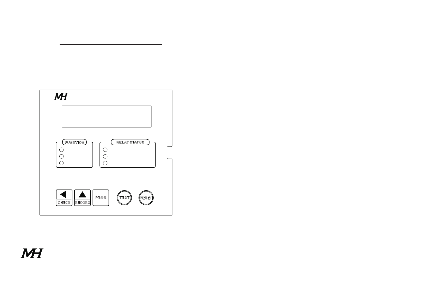
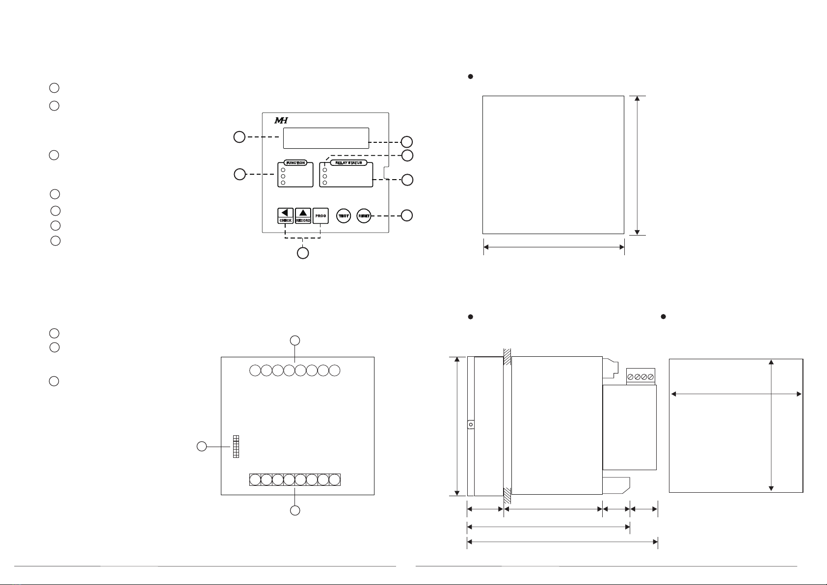
1. Hardware
1.1 Front
Real time system voltage reading
Function Indicators
Program : Programming mode
Check : Display of setting
Record : Display of memory records
Type of Fault indicator
Over Voltage
Under Voltage
Trip status indicator
Function buttons
Test and Reset buttons
Trip Info display
1.2 Terminals description
Aux power and Contacts
Voltage Input
Module terminal
2. Installation and Connections
Plug in Module
2.1 Outlook and Cut out dimension (mm)
Back View
Side View Cut Out
L31 : 380 V
NO_UV | TRIP_0V
OVER VOLTAGE
UNDER VOLTAGE
OVER & UNDER VOLTAGE RELAY
OUV400
3 4
PROG
RECORD
CHECK
L1 L2 L3
L1
L2
L3
N
L
O
A
D
c a Ta Tc P2 P1
OVER UNDER AUX. POWER
AC/DC85~265V
L1 L2 L3
b
TEST
RESET
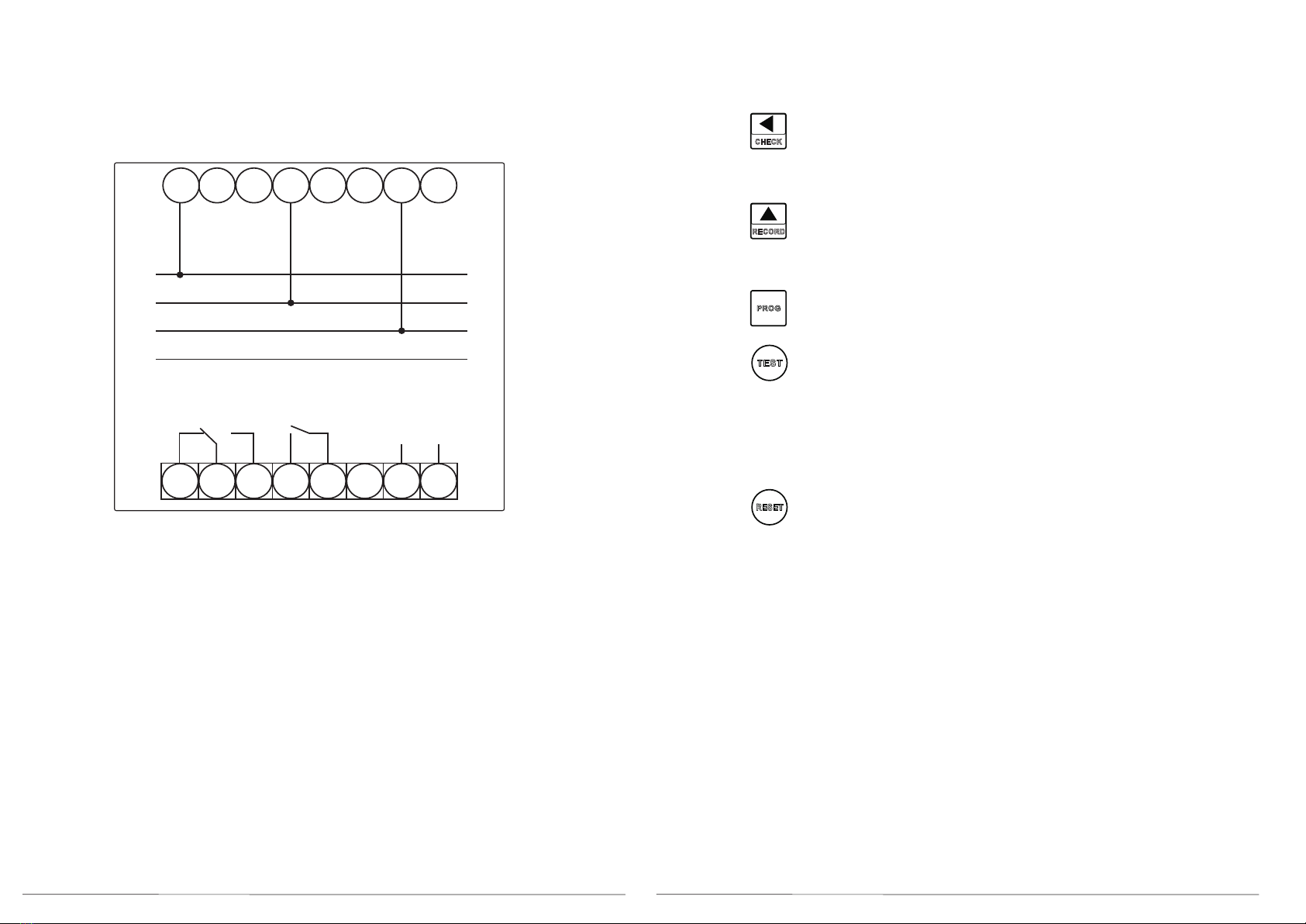
2.2 Connection diagram
Both L1-L1, L2-L2, L3-L3
terminals are internal linked
3. Display and button functions
3.1 Display screen button functions description
Display of setting values; (CHECK)
Short press to move next page (refer to 3.2)
Long press to return to the numeric display screen
Display of Trip records; ( RECORD)
Short press to move next page (refer to 3.2)
Long press to return to the numeric display screen
Enter the setting main menu (refer to 4.1)
Trip test function keys
Normal Non trip condition:
Press once to show ' PRESS TEST AGAIN TO CONFIRM'
Press once again to confirm
Display 'TEST OK' , Relay trip LED on and contact close.
Reset button
Trip condition
Trip via TEST button, Trip info area display 'TR_PB'
Press RESET, display 'RST TEST TRIP'. Relay reset
Trip via OV or UV, Relay reset when fault is removed (Relay = AUTO)
Trip info display ' TR_O' or 'TR_U' or 'TR_OU'
Press RESET, Trip info display will be clear.
** Relay will only reset via RESET when Relay = LATCH.
** TEST function is not possible when the relay is in trip condition
Refer to 3.2
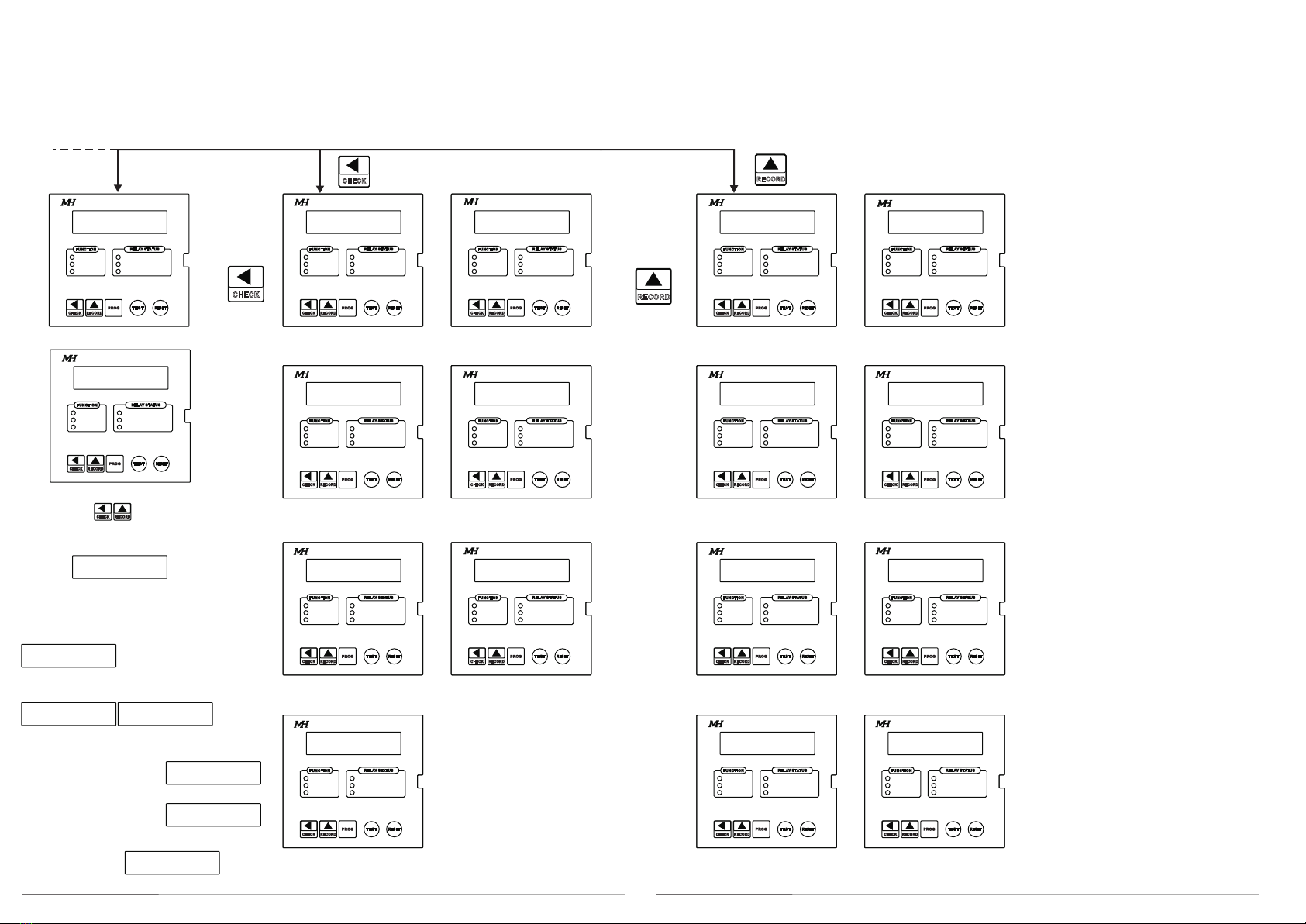
Input value display Setting parameter display (CHECK LED ON)
5 6
CHECK
CHECK
RECORD
RECORD
RELAY STATUS
PROG
CHECK
FUNCT ION
PROGRAM
CHECK
RECORD
TRIP
Over Volt age
RECOR D
Under Vol tag e
RELAY STATUS
PROG
CHECK
FUNCT ION
PROGRAM
CHECK
RECORD
TRIP
Over Volt age
RECOR D
Under Voltage
RELAY STATUS
PROG
CHECK
FUNCT ION
PROGRAM
CHECK
RECORD
TRIP
Over Volt age
RECOR D
Under Voltage
RELAY STATUS
PROG
CHECK
FUNCT ION
PROGRAM
CHECK
RECORD
TRIP
Over Volt age
RECOR D
Under Voltage
RELAY STATUS
PROG
CHECK
FUNCT ION
PROGRAM
CHECK
RECORD
TRIP
Over Volt age
RECOR D
Under Voltage
RELAY STATUS
PROG
CHECK
FUNCT ION
PROGRAM
CHECK
RECORD
TRIP
Over Volt age
RECOR D
RT C: _ HH_ _ ___MM SS
Under Voltage
RELAY STATUS
PROG
CHECK
FUNCT ION
PROGRAM
CHECK
RECORD
TRIP
Over Volt age
RECOR D
Under Voltage
RELAY STATUS
PROG
CHECK
FUNCT ION
PROGRAM
CHECK
RECORD
TRIP
Over Volt age
RECOR D
Under Voltage
RELAY STATUS
PROG
CHECK
FUNCT ION
PROGRAM
CHECK
RECORD
TRIP
Over Volt age
RECOR D
LAST: ___________
Under Voltage
RELAY STATUS
PROG
CHECK
FUNCT ION
PROGRAM
CHECK
RECORD
TRIP
Over Volt age
RECOR D
Under Voltage
RELAY STATUS
PROG
CHECK
FUNCT ION
PROGRAM
CHECK
RECORD
TRIP
Over Volt age
RECOR D
Under Voltage
RELAY STATUS
PROG
CHECK
FUNCT ION
PROGRAM
CHECK
RECORD
TRIP
Over Volt age
RECOR D
Under Voltage
RELAY STATUS
PROG
CHECK
FUNCT ION
PROGRAM
CHECK
RECORD
TRIP
Over Volt age
RECOR D
Under Voltage
RELAY STATUS
PROG
CHECK
FUNCT ION
PROGRAM
CHECK
RECORD
TRIP
Over Volt age
RECOR D
Under Voltage
RELAY STATUS
PROG
CHECK
FUNCT ION
PROGRAM
CHECK
RECORD
TRIP
Over Volt age
RECOR D
Under Voltage
RELAY STATUS
PROG
CHECK
FUNCT ION
PROGRAM
CHECK
RECORD
TRIP
Over Volt age
RECOR D
Under Voltage
L AST : Y YY Y- MM- DD_
RC. 3: ___________
RC. 3: Y YY Y- MM- DD_
RC. 4: ___________
RC. 2: Y YY Y- MM- DD_
RC. 2: ___________
RC. 4: Y YY Y- MM- DD_
CHECK R ECO RD
RESET
TEST
RESET
TEST
RESET
TEST
RESET
TEST
RESET
TEST
RESET
TEST
RESET
TEST
RESET
TEST
RESET
TEST
RESET
TEST
RESET
TEST
RESET
TEST
RESET
TEST
RESET
TEST
RESET
TEST
RESET
TEST
3. Display and button functions
3.2 Display screen descriptions
Trip record display (RECORD LED ON)
Press to change
between % or V
Example
Relay trips using TEST button
Screen display TRIP_PB, respective LED will ON
O/V : TRIP% RELAY
105 AUTO
OV threshold setting (%), Relay Reset
OV Reset level setting (%), Delay time (sec)
O/V : CLEAR% DELAY
103 0.100
O/V : TRIP% RELAY
95 AUTO
UV threshold setting (%), Relay Reset
U/V : CLEAR% DELAY
97 0.100
OV Reset level setting (%), Delay time (sec)
U/V : LO LIMIT %
000
UV non operating zone setting (%)
RTC : YYYY MM DD
09
06
2020
RTC (Real Time Clock) setting
* Available for model wtih RTC
RTC (Real Time Clock) setting
* Available for model wtih RTC
* Refer to 3.3 for detail
LAST:
NO TRIP RECORD
Last trip record memory
LAST: YYYY MM DD
HH : MM : SS
Latest trip time and date stamping
* Available for model wtih RTC
RC2:
NO TRIP RECORD
2nd trip record memory
RC2: YYYY MM DD
HH : MM : SS
2nd trip time and date stamping
* Available for model wtih RTC
RC3:
NO TRIP RECORD
RC. 2: Y YY Y- MM- DD_
RC3: YYYY MM DD
HH : MM : SS
3rd trip record memory
3rd trip time and date stamping
* Available for model wtih RTC
4th trip record memory
RC4:
NO TRIP RECORD
RC4: YYYY MM DD
HH : MM : SS
4th trip time and date stamping
* Available for model wtih RTC
Memory records base on FIFO;
example:
When the relay trip due to OV the record will
be save in LAST and the memory which is in the LAST
will be push to RC2, same will be as RC3 and RC4.
The record in RC4 will be deleted when new record is being
push from RC3.
Refer to 3.4 for details
*Will show only if there is trip record
*Will show only if there is trip record
Short press to change page, Long press to go back main display
Short press to change page, Long press to go back main display
OUV400
OVER & UNDER VOLTAGE RELAY
L12 : 380 V
L23 : 380 V
L31 : 380 V
L12, L23 Input value Display
L12 : 100 %
L23 : 100 %
L31 : 380 V
TRIP_0V
L31 : 380 V
TRIP_PB
RELAY STATUS
PROG
CHECK
FUNCT ION
PROGRAM
CHECK
RECORD
TRIP
Over Volt age
RECOR D
Under Vol tag e
RESET
TEST
OUV400
OVER & UNDER VOLTAGE RELAY
L31 Input value Display
OUV400
OUV400
OUV400
OUV400
OUV400
OUV400
OUV400 OUV400 OUV400
OUV400
OUV400
OUV400OUV400
OUV400
OUV400
OVER & UNDER VOLTAGE RELAY
OVER & UNDER VOLTAGE RELAY
OVER & UNDER VOLTAGE RELAY
OVER & UNDER VOLTAGE RELAY
OVER & UNDER VOLTAGE RELAY OVER & UNDER VOLTAGE RELAY OVER & UNDER VOLTAGE RELAY
OVER & UNDER VOLTAGE RELAY
OVER & UNDER VOLTAGE RELAY
OVER & UNDER VOLTAGE RELAY
OVER & UNDER VOLTAGE RELAY
OVER & UNDER VOLTAGE RELAY OVER & UNDER VOLTAGE RELAY OVER & UNDER VOLTAGE RELAY OVER & UNDER VOLTAGE RELAY
L31 : 380 V
TRIP_UV
** Refer to setting 'O/V SETTING'
If O/V contact operation setting: OFF
Screen display NO_UV
Trip information display area
Relay trips by OVER VOLTAGE or UNDER VOLTAGE
Screen display TPIP_OV or TRIP_UV, respective LED will ON
L31 : 380 V
NO_OV |
** Refer to setting 'U/V SETTING'
If U/V contact operation setting: OFF
Screen display NO_UV
L31 : 380 V
NO_UV |
If O/V and U/V contact operation setting: OFF
Screen display NO_OUV L31 : 380 V
NO_OUV |

7 8
1
2
3
1
2
3
4
4
1
2
3
1
2
3
1
2
1
2
2
3
1
2
2
1
1
3
1
2
1
2
1
2
1 1
1
2
1
2
1 1
1
2
1
2
2 2
O/ V: T RRI P % EL AY
1 0 5 AUT O
10 3 01 . 00
U/ V:
00 0
RT C : Y Y Y Y - MM- DD
HH: MM: SS
MODUL E P L UG I N:
RS4 8 5
RELAY STATUS
PROG
CHECK
FUNCT ION
PROGRAM
CHECK
RECORD
TRIP
RECOR D
RELAY STATUS
PROG
CHECK
FUNCT ION
PROGRAM
CHECK
RECORD
TRIP
RECOR D
RELAY STATUS
PROG
CHECK
FUNCT ION
PROGRAM
CHECK
RECORD
TRIP
RECOR D
RELAY STATUS
PROG
CHECK
FUNCT ION
PROGRAM
CHECK
RECORD
TRIP
RECOR D
RELAY STATUS
PROG
CHECK
FUNCT ION
PROGRAM
CHECK
RECORD
TRIP
RECOR D
RELAY STATUS
PROG
CHECK
FUNCT ION
PROGRAM
CHECK
RECORD
TRIP
RECOR D
RELAY STATUS
PROG
CHECK
FUNCT ION
PROGRAM
CHECK
RECORD
TRIP
RECOR D
RELAY STATUS
PROG
CHECK
FUNCT ION
PROGRAM
CHECK
RECORD
TRIP
RECOR D
RELAY STATUS
PROG
CHECK
FUNCT ION
PROGRAM
CHECK
RECORD
TRIP
RECOR D
RELAY STATUS
PROG
CHECK
FUNCT ION
PROGRAM
CHECK
RECORD
TRIP
RECOR D
Over Volt age
Under Vol tag e
Over Volt age
Under Vol tag e
Over Volt age
Under Vol tag e
Over Volt age
Under Vol tag e
Over Volt age
Under Vol tag e
Over Volt age
Under Voltage
Over Volt age
Under Voltage
Over Volt age
Under Voltage
Over Volt age
Under Voltage
Over Volt age
Under Voltage
RESET
TEST
RESET
TEST
RESET
TEST
RESET
TEST
RESET
TEST
RESET
TEST
RESET
TEST
RESET
TEST
RESET
TEST
RESET
TEST
3. Display and button functions
3.3 Setting parameters (CHECK mode) display example descritpions
O/V:
O/V: Over Voltage setting
Over Voltage threshold setting at 105%
Over Voltage contact operation setting: AUTO (Auto reset)
CHECK mode ON indication
O/V : CLEAR% DELAY O/V: Over Voltage setting
Over Voltage Reset value setting at 103%
Trip time delay setting at 1 sec
U/V : LO LIMIT % U/V: Under Voltage setting
UV non operating zone setting at 0%)
RTC: Date and Time stamping (If equip)
Year-Month-Day
Hour-Minutes-Second
E.g: Year-2020 Month-06 Day-10
Hour-08 Minutes-10 Second-15
RTC: 2020-06-10
08:10:15
Plug in module: only will display when the module is plug in
RS485: Module plug in is for RS485
3.4 Trip Record (Record) display example descritpions
LAST: Most recent Tirp record
No Trip record: No tripping is detected
LAST: Most recent Tirp record date and Time stamping
(Must equip with RTC function)
# Not show if there is no record
LAST TRIP OU123
L1: 60.1 % UUU LAST TRIP. OU123
Most recent trip record and fault voltage situation when trip
L1: 60.1% UUU
Note: O mean Over Voltage
U mean Under Voltage
Description: Trip at 60.1% at L1, L1L2L3 undervoltage pickup
Tripping record in %
LAST: Most recent trip date and time stamping (If equip)
2020 (Year)- 06 (Month)-01 (Day)
17 (Hour):03 (Minutes):05 (Second)
TRIP RC.2 OU123
L1: 0.0 % UOU TRIP RC.2 OU123
L1: 0.0% UOU
Note: O mean Over Voltage
U mean Under Voltage
Description: Trip at 0.0% at L1, L1, L3 undervoltage and L2 overvoltage pickup
Tripping record in %
2nd trip record and fault voltage situation when trip
LAST: 2020-06-01
17:03:05
NO TRIP RECORD
LAST:
LAST: YYYY-MM-DD
HH: MM: SS
OUV400
OUV400
OUV400
OUV400
OUV400
OUV400
OUV400
OUV400
OUV400
OUV400

9 10
P R E SS T E S T A GAI N
T O CONF I RM
RELAY STATUS
RESET
PROG
CHECK
FUNCT ION
PROGRAM
CHECK
RECORD
TRIP
RECOR D
RELAY STATUS
PROG
CHECK
FUNCT ION
PROGRAM
CHECK
RECORD
TRIP
RECOR D
RELAY STATUS
PROG
CHECK
FUNCT ION
PROGRAM
CHECK
RECORD
TRIP
RECOR D
Over Volt age
Under Voltage
Over Volt age
Under Voltage
Over Volt age
Under Voltage
RESET
TEST
RESET
TEST
RESET
TEST
3. Display and button functions
3.5 Abnormal, Trip, Test and Check functions
3.5.1 Abnormal display descriptions
During abnormality,
the display will switch back to the main display
The Phase Number
will flash when abnormality is detected
(Setting: OVER FLASH=YES)
L1, L2 detected abnormality (Overvoltage)
The detected fault (Overvoltage) LED and
Trip LED will flash.
3.5.2 Triping display descriptions
After trip, if the fault is clear,
the display will switch to memory record page
Trip memory record display
Refer to 3.4
Latest trip record memory
Record LED indicates it is in
Record memory page
Present status
Trip LED indicates the relay had trip
Overvoltage LED indicates Overvoltage fault
3.5.3 Test and Reset function
Normal status:
Press the display will show ' PRESS TEST AGAIN TO CONFIRM'
TEST
TEST
Press again to trip the relay, the display will show ' TEST OK'
Trip status:
Press to reset the relay to normal status, the display will show ' RST TEST TRIP'
RESET
RESET BUTTON
TEST BUTTON
3.5.4 Check function description
CHECK
1. Press button to check the setting of the relay ( Refer to 3.2 for detail)
RECORD
Press button to check the record memory of the relay ( Refer to 3.2 for detail)
Long Press of either or will return back to main display
CHECK RECORD
2. If no button is press for 3 mins, the display will automatically toggles between the
CHECK and RECORD (CHECK and RECORD LED on respectively and show its content.
OUV400
OUV400
OUV400
OVER & UNDER VOLTAGE RELAY
L12 : 380 V
L23 : 380 V
LAST TRIP. OU123
L12 : 168% 00
11 12
��
PROG
PROG
RECORD
CHECK
CHECK
��
PROG
RECORD
CHECK
CHECK
�
CHECK
��
PROG
RECORD
CHECK
CHECK
��
PROG
RECORD
CHECK
CHECK
PROG
RECORD
CHECK
PROG
RECORD
CHECK
RECORD
RECORD
PROG
CHECK
PROG
PROG
RECORD
PROG
RECORD
PROG
RECORD
PROG
RECORD
PROG
RECORD
PROG
RECORD
P AS S C ODE
00
105 AUT O
103 01. 00 08 00 01
001 9600 n , 8 , 1
2018 11 01
NoY e s3 8 0
01. 00
097
095 AUT O
REL AY STATU S
PRO G
CHECK
FUN CTIO N
PROGRAM
CHECK
REC ORD
TRI P
REC ORD
REL AY STATU S
PRO G
CHECK
FUNCTION
PROGRAM
CHECK
REC ORD
TRI P
RECORD
Ove r Voltag e
Und er Volta ge
OVER& UNDER V OLTAG E REL AY
OUV400
REL AY STATU S
PRO G
CHECK
FUN CTIO N
PROGRAM
CHECK
REC ORD
TRI P
REC ORD
REL AY STATU S
PRO G
CHECK
FUN CTIO N
PROGRAM
CHECK
REC ORD
TRI P
REC ORD
REL AY STATU S
PRO G
CHECK
FUNCTION
PROGRAM
CHECK
RECORD
TRI P
RECORD
REL AY STATU S
PRO G
CHECK
FUNCTION
PROGRAM
CHECK
RECORD
TRI P
RECORD
REL AY STATU S
PRO G
CHECK
FUNCTION
PROGRAM
CHECK
RECORD
TRI P
RECORD
REL AY STATU S
PRO G
CHECK
FUN CTIO N
PROGRAM
CHECK
REC ORD
TRI P
REC ORD
REL AY STATU S
PRO G
CHECK
FUN CTIO N
PROGRAM
CHECK
REC ORD
TRI P
REC ORD
REL AY STATU S
PRO G
CHECK
FUNCTION
PROGRAM
CHECK
REC ORD
TRI P
REC ORD
REL AY STATU S
PRO G
CHECK
FUNCTION
PROGRAM
CHECK
RECORD
TRI P
RECORD
REL AY STATU S
PRO G
CHECK
FUNCTION
PROGRAM
CHECK
RECORD
TRI P
RECORD
REL AY STATU S
PRO G
CHECK
FUNCTION
PROGRAM
CHECK
REC ORD
TRI P
RECORD
REL AY STATU S
PRO G
CHECK
FUNCTION
PROGRAM
CHECK
RECORD
TRI P
RECORD
REL AY STATU S
PRO G
CHECK
FUNCTION
PROGRAM
CHECK
REC ORD
TRI P
RECORD
REL AY STATU S
PRO G
CHECK
FUNCTION
PROGRAM
CHECK
RECORD
TRI P
RECORD
REL AY STATU S
PRO G
CHECK
FUNCTION
PROGRAM
CHECK
REC ORD
TRI P
RECORD
Of f
REL AY STATU S
PRO G
CHECK
FUNCTION
PROGRAM
CHECK
REC ORD
TRI P
REC ORD
BOT H
REL AY STATU S
PRO G
CHECK
FUNCTION
PROGRAM
CHECK
REC ORD
TRI P
REC ORD
L 123
REL AY STATU S
PRO G
CHECK
FUNCTION
PROGRAM
CHE CK
REC ORD
TRI P
REC ORD
OVER& UNDER V OLTAG E REL AY OVER& UNDER V OLTAG E REL AY OVER& UNDER V OLTAG E REL AY OVER& UNDER V OLTAG E REL AY OVER& UNDER V OLTAG E REL AY OVER& UNDER V OLTAG E REL AY
OVER& UNDER V OLTAG E REL AY
OVER& UNDER V OLTAG E REL AY
OVER& UNDER V OLTAG E REL AY
OVER& UNDER V OLTAG E REL AY
000
REL AY STATU S
PRO G
CHECK
FUNCTION
PROGRAM
CHECK
RECORD
TRI P
RECORD
OVER& UNDER V OLTAG E REL AY
OVER& UNDER V OLTAG E REL AY
0001
REL AY STATU S
PRO G
CHECK
FUN CTIO N
PROGRAM
CHECK
REC ORD
TRI P
REC ORD
OVER& UNDER V OLTAG E REL AY
50
REL AY STATU S
PRO G
CHECK
FUN CTIO N
PROGRAM
CHECK
REC ORD
TRI P
REC ORD
OVER& UNDER V OLTAG E REL AY
OVER& UNDER V OLTAG E REL AY
OVER& UNDER V OLTAG E REL AY
OVER& UNDER V OLTAG E REL AY
OVER& UNDER V OLTAG E REL AY
OVER& UNDER V OLTAG E REL AY OVER& UNDER V OLTAG E REL AY OVER& UNDER V OLTAG E REL AY
OVER& UNDER V OLTAG E REL AY
Ove r Voltag e
Und er Volta ge
OUV 400
Ove r Voltag e
Und er Volta ge
OUV 400
Ove r Voltag e
Und er Volta ge
OUV 400
Ove r Voltag e
Und er Volta ge
OUV 400
Ove r Voltag e
Und er Volta ge
OUV 400
Ove r Voltag e
Und er Volta ge
OUV 400
Ove r Voltag e
Und er Volta ge
OUV 400
Ove r Voltag e
Und er Volta ge
OUV 400
Ove r Voltag e
Und er Volta ge
OUV 400
Ove r Voltag e
Und er Volta ge
OUV 400
Ove r Voltag e
Und er Volta ge
OUV 400
Ove r Voltag e
Und er Volta ge
OUV 400
Ove r Voltag e
Und er Volta ge
OUV 400
Ove r Voltag e
Und er Volta ge
OUV400
Ove r Voltag e
Und er Volta ge
OUV 400
Ove r Voltag e
Und er Volta ge
OUV 400
Ove r Voltag e
Und er Volta ge
OUV 400
Ove r Voltag e
Und er Volta ge
OUV 400
Ove r Voltag e
Und er Volta ge
OUV 400
Ove r Voltag e
Und er Volta ge
OUV 400
Ove r Voltag e
Und er Volta ge
OUV 400
Ove r Voltag e
Und er Volta ge
OUV400
CHE CK
REC ORD
TEST
00
REL AY STATU S
PRO G
CHECK
FUNCTION
PROGRAM
CHECK
REC ORD
TRI P
REC ORD
OVER& UNDER V OLTAG E REL AY
Ove r Voltag e
Und er Volta ge
OUV400
RES ET
TES T
RESE T
TEST
RESE T
TEST
RESE T
RES ET
TES T
RESET
TES T
RES ET
TES T
RESET
TES T
RES ET
TES T
RESET
TES T
RES ET
TES T
RES ET
TES T
RES ET
TES T
RESET
TES T
RESET
TES T
RES ET
TES T
RESET
TES T
RES ET
TES T
RESET
TES T
RES ET
TES T
RESET
TES T
RES ET
TES T
RESET
TES T
RES ET
TES T
RES ET
TES T
RES ET
TES T
RES ET
TES T
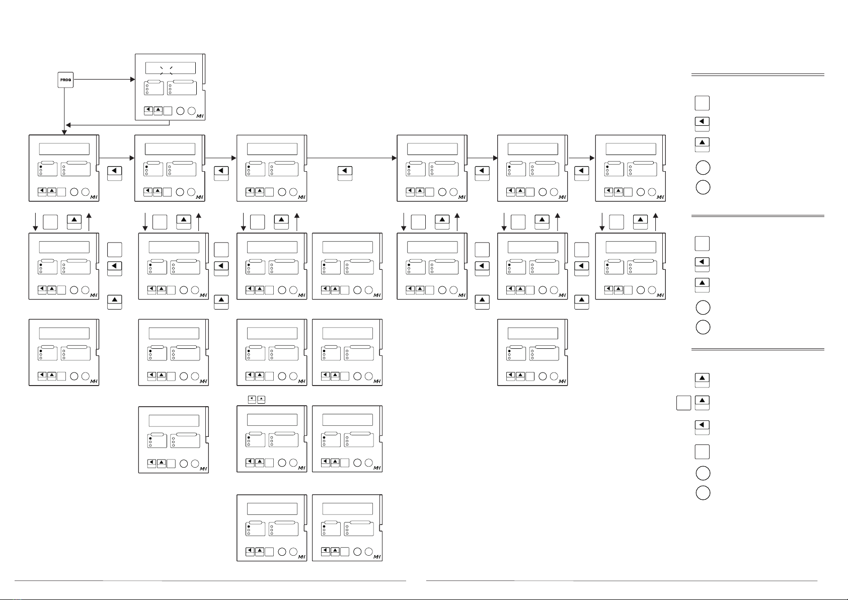
4. Setting Configurations and Button function
4.1: Setting menu (Refer 4.3 for detail)
Password ≠0
Password = 0
Password is disable by default (00)
'Error' will display when wrong password is enter
O/V main menu U/V main menu Adjustment main menu
O/V Pickup (%)
Relay setting
O/V reset (%)
Delay time (sec)
U/V Pickup (%)
Relay setting
U/V reset (%)
Delay time (sec)
U/V non operating value (%)
System Voltage Pickup Flashing Clear memory
PT ratio
(Press to move decimal point)
Frequency
Notation Display Password
Trip info display
CHECK mode
Auto scrolling
Reset main menu RTC main menu
Year, Month and Day
Hour, min and second
Adress, baud rate, Frame
RS485 main menu
If equip with RTC
Only display when plug in
the RS584 module
4.2 Buttons Function:
Descriptions:
Main menu
Enter into Sub menu
Switch between main menus
Return to main display menu
No effect
Reset
Sub menu
Enter into Setting
Switch between Sub menus
Return to Main menu
No effect
Reset
Setting
Increase value
Press 2s + 5, 4s +10
Decrease value
Press 2s - 5, 4s -10
Move between digits
Save and return to sub menu
No effect
Reset
O/V SETTING_ U/V SETTING_ ADJUSTMENT_ CLEAR RECORD_ RTC SETTING_ RS485_
O/V TRIP% RELAY
O/V CLEAR% DELAY
U/V TRIP% RELAY
U/V CLEAR% DELAY
U/V LO LIMIT%
VOLTAGE OVER FLASH
PT RATIO CHECK DELAY SEC
FREQUENCY DISP TRIP INFO
DISPLAY STYLE CHANGE PASSCODE
CLEAR RECORD RTC YYYY - MM - DD
RTC HH: MM: SS
ADR BAUDR FRAME
13 14
P ASS CODE
00
O/ V SET T I NG_
O/ V TRI P % REL AY
1 05 AUT O
�
O/ V CL EAR% DEL AY
103 01. 00
U/ V SE T T I NG_
U/ V T RI P % RE L AY
095 AUTO
U/ V CL E AR% DEL AY
01. 00097
ADJ UST MENT_
VOL T AGE
380
CHECK
RECORD
RECORD
CHECK
PR OG
PR OG
PR OG
RECORD
RECORD
PR OG
PR OG
PR OG
CHECK
RECORD
RECORD
PR OG
PR OG
PR OG
CHECK
RECORD
RECORD
PR OG
PR OG
PR OG
RECORD
RECORD
PR OG
PR OG
PR OG
CHECK
RECORD
RECORD
PR OG
PR OG
PR OG
U/ V L O L I MI T %
000
CHECK
RECORD
RECORD
PR OG
PR OG
PR OG
P T RAT I O
000 1
RECORD
RECORD
PR OG
PR OG
PR OG
F REQUENCY
50
RECORD
RECORD
PR OG
PR OG
PR OG
CHE CK
REC ORD
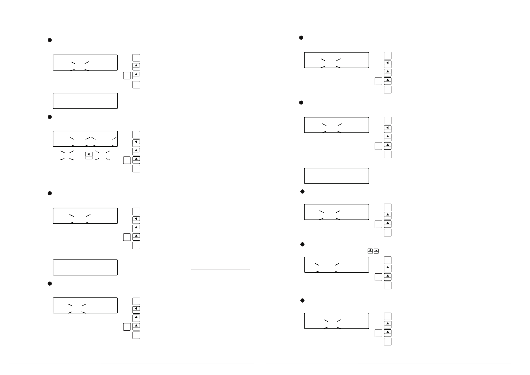
4.3 Configuration descriptions: 'PROGRAM' LED is ON
Enter Password:
Range: 00 - 99
00 = Password disable
Enter into value setting, digit flashing
Value increase, long press to increase speed
Value decrease, long press to increase speed
Confirm setting, enter into Setting if password is right
'ERROR' will show if it is wrong password.
O/V Setting main menu
O/V Trip % and Relay setting
Range: Trip%: 100-130%, Relay: OFF, AUTO, LATCH
Enter into value setting, digit flashing
Move the cursor to next digit
Value increase, long press to increase speed
Value decrease, long press to increase speed
Confirm setting and return to sub menu
Move the cursor to next digit
RELAY: OFF (Non operation), AUTO: Auto reset, LATCH: Manual reset (Press reset button to reset)
O/V Reset % and Delay setting
Range: Reset%: 100-130%, Delay time: 00-60sec
Enter into value setting, digit flashing
Move the cursor to next digit
Value increase, long press to increase speed
Value decrease, long press to increase speed
Confirm setting and return to sub menu
U/V Setting main menu
Range: Trip%: 70-100%, Relay: OFF, AUTO, LATCH
U/V Trip % and Relay setting
Enter into value setting, digit flashing
Move the cursor to next digit
Value increase, long press to increase speed
Value decrease, long press to increase speed
Confirm setting and return to sub menu
RELAY: OFF (Non operation), AUTO: Auto reset, LATCH: Manual reset (Press reset button to reset)
U/V Reset % and Delay setting
Range: Reset%: 70-100%, Delay time: 00-60sec
Enter into value setting, digit flashing
Move the cursor to next digit
Value increase, long press to increase speed
Value decrease, long press to increase speed
Confirm setting and return to sub menu
U/V Low limit % setting
Range: 000-100%
Enter into value setting, digit flashing
Move the cursor to next digit
Value increase, long press to increase speed
Value decrease, long press to increase speed
Confirm setting and return to sub menu
Adjustment setting main menu
PT ratio setting
Range: 60-480V
System Voltage setting
Enter into value setting, digit flashing
Value increase, long press to increase speed
Value decrease, long press to increase speed
Confirm setting and return to sub menu
Range: 0.001-9999, Press to change decimal place
Enter into value setting, digit flashing
Value increase, long press to increase speed
Value decrease, long press to increase speed
Confirm setting and return to sub menu
Frequency setting
Range: 50 or 60Hz
Enter into value setting, digit flashing
Value increase, long press to increase speed
Value decrease, long press to increase speed
Confirm setting and return to sub menu

15 16
OVER F L ASH
Y e s
RECORD
RECORD
PR OG
PR OG
PR OG
DI SP T RI P I NF O
BOT H
RECORD
RECORD
PR OG
PR OG
PR OG
CHECK DEL AY SEC
Of f
RECORD
RECORD
PR OG
PR OG
PR OG
CL EAR RECORD_
CL EAR RECORD
No
RECORD
RECORD
PR OG
PR OG
PR OG
RS485 _
ADR BAUDR F RAME
001 9 600 n, 8, 1
RT C SE T T I NG_
RT C Y Y Y Y - MM- DD
201 8 11 01
RTC HH: MM: SS
08 00 0 1
CHECK
RECORD
RECORD
PR OG
PR OG
PR OG
CHECK
RECORD
RECORD
PR OG
PR OG
PR OG
RECORD
RECORD
PR OG
PR OG
PR OG
CHANGE P ASSCODE
00
RECORD
RECORD
PR OG
PR OG
PR OG
Scroll Delay Time
Range: 1 - 3 sec
SCROLL DELAY SEC
3
Enter into value setting, digit flashing
Value increase, long press to increase speed
Value decrease, long press to increase speed
Confirm setting and return to sub menu
Enter into value setting, digit flashing
Value increase, long press to increase speed
Value decrease, long press to increase speed
Confirm setting and return to sub menu
Enter into value setting, digit flashing
Value increase, long press to increase speed
Value decrease, long press to increase speed
Confirm setting and return to sub menu
Enter into value setting, digit flashing
Value increase
Value decrease
Confirm setting and return to sub menu
Enter into value setting, digit flashing
Value increase, long press to increase speed
Value decrease, long press to increase speed
Confirm setting and return to sub menu
Over thershold Flashing
Range: No - Yes
CHECK mode auto scroll time
Range: Off - 240sec
Trip info display setting
Range: NO, OULED, INFO, BOTH
NO: Disable
OULED: Over Voltage or
Under Voltage LED ON
INFO: Display TR_O or TR_U or TR_OU
BOTH: Equip with both OULED AND INFO function
Changing Password (0 = disable)
Range: 01 - 99
Clear Record Setting main menu
Clear Trip Record
Range: No - Yes
Enter into value setting, digit flashing
Value increase, long press to increase speed
Value decrease, long press to increase speed
Confirm setting and return to sub menu
RTC Setting main menu (Available if equip)
RTC Year-Month-Days, Hour-Min-Sec Setting
Enter into value setting, digit flashing
Value increase, long press to increase speed
Value decrease, long press to increase speed
Confirm setting and return to sub menu
Move cursor to next digit.
RS485 main menu (Enable when module is plug in)
Address, Buad rate, Frame Setting
Range: Address: 1 - 255, Baud rate: 1200 - 38400, Frame: n,8,1 - n,8,2
Enter into value setting, digit flashing
Value increase, long press to increase speed
Value decrease, long press to increase speed
Confirm setting and return to sub menu
Move cursor to next digit.

17 18
5. Specifications
1. Protection and Funcationalilty description (ANSI)
Timed and instantaneous Overvoltage --------------------------------------------------- 59T/59I
Timed and instantaneous Undervoltage -------------------------------------------------- 27T/27I
2. Maximum Delay Time: 60 sec
3. Digital Measurement --------------------------------------- True RMS at 64 samples per cycle
4. Supply Voltage --------------------AC85-265V (Other voltages are available upon request)
5. Power consumption ------------------------------------------------------------------------------≤4VA
6. System Voltage setting -------------------------------------------------------------- 60~480V (L-L)
7. Pick up voltage level
Overvoltage -------------------------------------------------------- 100~130% of System voltage
Undervoltage -------------------------------------------------------- 70~100% of System voltage
8. Time & Relay Reset voltage level
Overvoltage ---------------------------------------------------------100~130% of System voltage
Undervoltage -------------------------------------------------------- 70~100% of System voltage
9. Pickup accuracy ---------------------------------------------------------------- ± 0.5% of full scale
Reset accuracy -------------------------------------------------------------------- ± 1% of full scale
Time accuracy -------------------------- ± 3% of trip time or ± 20ms (Whichever is greater)
10. Tripping Relay --------------------------------------- (overvoltage) Contact : 1c 250Vac, 5A
( undervoltage) Contact: 1a 250Vac, 5A
11. LCD indication ----------------------------------------------------------------------- 16 x 2 display
Real time 3 digits display (L-L voltage)
12. Trip indication ---------------------------------------------------------------------Red LED for trip
13. Communication ------------------------------------------------------ ----------RS485 (Optional)
14. Operating temperature range ------------------------------------------------------0~60 deg C
15. Storage temperature range ----------------------------------------------------- -10~70 deg C
16. Max. relative humidity -------------------------------------------------------------------------95%
17. Dielectric strength (IEC 688) ----------- AC2kV / 1 min Input / Output / Power / Case
18. Electrical fast transient / burst ------------------------------- According to IEC 61000-4-4
19. Withstanding impluse voltage ------------------------------- According to IEC 61000-4-5
20. Voltage dips and short interruptions ---------------------- According to IEC 61000-4-11
21. Electromagnetic wave ----------- Non-operation for radio frequency at 130~180MHz
and 400~500MHz (by walkie-talkie of 5W)
22. Enclosure protection -------------------------------------------------------------------------- IP54
23. Connection ---------------------------------------------------------------- Plug-in terminal block

19 20
Start of
frame
Addres s
Field
Function
Code
Data
Field
Error
Check
End of
Frame
Start Bit DataBit Pari ty Stop Frame
1 8 None 2
1 8 Odd 1
1 8 Even 1
1 8 None 1
6. Communication
6.1 Protocol
Using MODBUS communication protocol,
30 devices/loop (Repeater is need for > 30 devices)
6.2 Transmission
RTU mode, Half-Duplex
6.3 Message Format
6.3.1 Basic Format
Start of Frame : Interval of no transmission equal to or in excess of the
time corresponding to 4 characters
Address Field : Address of all terminals (Range: 1~255)
Function Code : 03H;Read, 06H;Write
Data Field : This field contains information that the slave will use to carry
out the command from the master unit
Error Check : 16 bits CRC
End of Frame : Internal of no transmission equal to or in excess of the
time corresponding to 4 characters
6.3.2 Bit Per Byte: Able to set in the RS485 setting menu
n, 8, 2
o, 8, 1
E, 8, 1
n, 8, 1
6.4 Read Data Register
Query:
Start of
Frame
Address
Field
Function
Code
Start
Address
Hi
Start
Address
Lo
Number
of
Word
Lo
Number
of
Word
Hi
Error
Check
End of
Frame
01H~FFH 03H 0~nnH 1~nnH CRC Lo CRC Hi
0~nnH 0H
1 Byte 2 Bytes
1 Byte 2 Bytes 2 Bytes
Response: (no error received)
Start of
Frame
Address
Field
Function
Code
Error
Check
End of
Frame
Number of
Data Bytes
count
D0, D1....Dn
(Hi, Lo, Hi, Lo...)
01H~FFH 03H CRC Lo CRC Hi
1 Byte 1 Byte 1 Byte 2 Bytes
6.5 Write Data register
Query
Response: Single message
Start of
Frame
Address
Field
Function
Code
Start
Address
Lo
Error
Check
End of
Frame
Start
Address
Hi
Value
Hi..
Value
..Lo
01H~FFH 06H 0~nnH Setting Value CRC Lo
1 Byte 2 Bytes2 or 4 Byte
1 Byte 2 Bytes
0~nnH CRC Hi
01H~FFH 06H 0~nnH Setting Value CRC Lo
1 Byte 2 Bytes2 or 4 Bytes
1 Byte 2 Bytes
0~nnH CRC Hi
Start of
Frame
Address
Field
Function
Code
Start
Address
Lo
Error
Check
End of
Frame
Start
Address
Hi
Value
Hi..
Value
..Lo
6.6 Error Response (Error message received)
Start of
Frame
Address
Field
Function
Code
Error
Check
End of
Frame
Error
Code
01H~FFH
1 Byte 1 Byte 1 Byte 2 Bytes
CRC Lo CRC Hi
83H or 86H
Function Code: The function code requested with MSB set to 1
Error Code: 01: Error Function
02: Error Data Address
03: Error Data Value

static unsigned char auchCRCHi[]={
0x00,0xc1,0x81,0x40,0x01,0xc0,0x80,0x41,0x01,0xc0,
0x80,0x41,0x00,0xc1,0x81,0x40,0x01,0xc0,0x80,0x41,
0x00,0xc1,0x81,0x40,0x00,0xc1,0x81,0x40,0x01,0xc0,
0x80,0x41,0x01,0xc0,0x80,0x41,0x00,0xc1,0x81,0x40,
0x00,0xc1,0x81,0x40,0x01,0xc0,0x80,0x41,0x00,0xc1,
0x81,0x40,0x01,0xc0,0x80,0x41,0x01,0xc0,0x80,0x41,
0x00,0xc1,0x81,0x40,0x01,0xc0,0x80,0x41,0x00,0xc1,
0x81,0x40,0x00,0xc1,0x81,0x40,0x01,0xc0,0x80,0x41,
0x00,0xc1,0x81,0x40,0x01,0xc0,0x80,0x41,0x01,0xc0,
0x80,0x41,0x00,0xc1,0x81,0x40,0x00,0xc1,0x81,0x40,
0x01,0xc0,0x80,0x41,0x01,0xc0,0x80,0x41,0x00,0xc1,
0x81,0x40,0x01,0xc0,0x80,0x41,0x00,0xc1,0x81,0x40,
0x00,0xc1,0x81,0x40,0x01,0xc0,0x80,0x41,0x01,0xc0,
0x80,0x41,0x00,0xc1,0x81,0x40,0x00,0xc1,0x81,0x40,
0x01,0xc0,0x80,0x41,0x00,0xc1,0x81,0x40,0x01,0xc0,
0x80,0x41,0x01,0xc0,0x80,0x41,0x00,0xc1,0x81,0x40,
0x00,0xc1,0x81,0x40,0x01,0xc0,0x80,0x41,0x01,0xc0,
0x80,0x41,0x00,0xc1,0x81,0x40,0x01,0xc0,0x80,0x41,
0x00,0xc1,0x81,0x40,0x00,0xc1,0x81,0x40,0x01,0xc0,
0x80,0x41,0x00,0xc1,0x81,0x40,0x01,0xc0,0x80,0x41,
0x01,0xc0,0x80,0x41,0x00,0xc1,0x81,0x40,0x01,0xc0,
0x80,0x41,0x00,0xc1,0x81,0x40,0x00,0xc1,0x81,0x40,
0x01,0xc0,0x80,0x41,0x01,0xc0,0x80,0x41,0x00,0xc1,
0x81,0x40,0x00,0xc1,0x81,0x40,0x01,0xc0,0x80,0x41,
0x00,0xc1,0x81,0x40,0x01,0xc0,0x80,0x41,0x01,0xc0,
0x80,0x41,0x00,0xc1,0x81,0x40};
static unsigned char auchCRCLo[]={
0x00,0xc0,0xc1,0x01,0xc3,0x03,0x02,0xc2,0xc6,0x06,
0x07,0xc7,0x05,0xc5,0xc4,0x04,0xcc,0x0c,0x0d,0xcd,
0x0f,0xcf,0xce,0x0e,0x0a,0xca,0xcb,0x0b,0xc9,0x09,
0x08,0xc8,0xd8,0x18,0x19,0xd9,0x1b,0xdb,0xda,0x1a,
0x1e,0xde,0xdf,0x1f,0xdd,0x1d,0x1c,0xdc,0x14,0xd4,
0xd5,0x15,0xd7,0x17,0x16,0xd6,0xd2,0x12,0x13,0xd3,
0x11,0xd1,0xd0,0x10,0xf0,0x30,0x31,0xf1,0x33,0xf3,
0xf2,0x32,0x36,0xf6,0xf7,0x37,0xf5,0x35,0x34,0xf4,
0x3c,0xfc,0xfd,0x3d,0xff,0x3f,0x3e,0xfe,0xfa,0x3a,
0x3b,0xfb,0x39,0xf9,0xf8,0x38,0x28,0xe8,0xe9,0x29,
0xeb,0x2b,0x2a,0xea,0xee,0x2e,0x2f,0xef,0x2d,0xed,
0xec,0x2c,0xe4,0x24,0x25,0xe5,0x27,0xe7,0xe6,0x26,
0x22,0xe2,0xe3,0x23,0xe1,0x21,0x20,0xe0,0xa0,0x60,
0x61,0xa1,0x63,0xa3,0xa2,0x62,0x66,0xa6,0xa7,0x67,
0xa5,0x65,0x64,0xa4,0x6c,0xac,0xad,0x6d,0xaf,0x6f,
0x6e,0xae,0xaa,0x6a,0x6b,0xab,0x69,0xa9,0xa8,0x68,
0x78,0xb8,0xb9,0x79,0xbb,0x7b,0x7a,0xba,0xbe,0x7e,
0x7f,0xbf,0x7d,0xbd,0xbc,0x7c,0xb4,0x74,0x75,0xb5,
0x77,0xb7,0xb6,0x76,0x72,0xb2,0xb3,0x73,0xb1,0x71,
0x70,0xb0,0x50,0x90,0x91,0x51,0x93,0x53,0x52,0x92,
0x96,0x56,0x57,0x97,0x55,0x95,0x94,0x54,0x9c,0x5c,
0x5d,0x9d,0x5f,0x9f,0x9e,0x5e,0x5a,0x9a,0x9b,0x5b,
0x99,0x59,0x58,0x98,0x88,0x48,0x49,0x89,0x4b,0x8b,
0x8a,0x4a,0x4e,0x8e,0x8f,0x4f,0x8d,0x4d,0x4c,0x8c,
0x44,0x84,0x85,0x45,0x87,0x47,0x46,0x86,0x82,0x42,
0x43,0x83,0x41,0x81,0x80,0x40};
21 22
6.7 CRC calculation
CRC check field is formed by 2bytes containing a 16bit binary value. The CRC is calculated
by the transmitting device, which adds it to the end of the message. The receiving device
calculates it once more and compares it to the value received. If the two values do not
conincide, an error occurs.
Calculating process:
1. Load a 16bit data register (CRC register) with 0XFFFF
2. Exculsive OR the first byte of the message with the low order byte of the CRC register and
leave the result in the register itself.
3. Shift the CRC register one bit to the right (by inserting a 0 on the left)
4. If the bit shifted out to the right is 0 repeat step 3. If the bit is 1, exculsive OR the CRC
register with the 0XA001.
5. Repeat step 3 and 4 unit 8 shifts had been carried out.
6. Repeat step 3 - 5 for the bytes of the message. The final content of the CRC register is the
CRC value.
7. When adding the CRC to the message, first enter the lower part of the CRC register, follow
by the upper part of the CRC register
CRC calculation program
/*CRC generation Function with "C" language*/
/*Msg:*message to calculate CRC upon*/
/* usDatalen: number of bytes in message*/
unsigned int CRC16 (char *Msg, unsigned char usDatalen)
{
unsigned char uchCRCHi=0xFF;/*CRC highbyte*/
unsigned char uchCRCLo=0xFF;/*CRC lowbyte*/
unsigned char uIndex;
While (usDatalen--)/*pass through message buffer*/
{
uIndex=uchCRCHi^*Msg++;/*calculate the CRC*/
uchCRCHi=uchCRCLo^auchCRCHi[uIndex];
uchCRCLo=auchCRCLo[uIndex];
}
}
return (uchCRCHi<< 8 | uchCRCLo);

23 24
0000H I nteger 1 R
000DH I nteger 1 R/W
0-1 (1: Clear)
000CH I nteger 1 R/W
000BH I nteger 1 R/W
000A H I nteger 1 R/W
0004H I nteger 1 R
0-1 (0:50, 1:60)
0003H I nteger 1 R
60-480V
0002H I nteger 1 R
0-6000 (0.01s)
0001H I nteger 1 R
70-100%
000FH I nteger 1 R/W 0001-9999,
0512 0200H I nteger 1 R
0525 020DH I nteger 1 R
0524 020CH I nteger 1 R
0523 020BH I nteger 1 R
0522 020A H I nteger 1 R
0521 0209H I nteger 1 R
0520 0208H I nteger 1 R
0519 0207H I nteger 1 R
0518 0206H I nteger 1 R
0517 0205H I nteger 1 R
0516 0204H I nteger 1 R
0514 0202H I nteger 1 R
0513 0201H I nteger 1 R
0.1%
0.1%
0.1%
0.1%
0.1%
0009H I nteger 1 R/W
0008H I nteger 1 R
0007H I nteger 1 R
0006H I nteger 1 R
0005H I nteger 1R
000EH I nteger 1 R/W
0515 0203H I nteger 1 R
0010H I nteger 1 R/W 1 - 255
0011H I nteger 1 R/W 0 -3
0012H I nteger 1 R/W 0-100 (*)
0013H I nteger 1 R/W
0014H I nteger 1 R/W
0015H I nteger 1 R/W
0016H I nteger 1 R/W
1 -12
0017H I nteger 1 R/W
1 - 31
0018H I nteger 1 R/W
0 - 23
0019H I nteger 1 R/W
0 - 59
001A H I nteger 1 R/W
0 - 59
0531 0213H I nteger 1 R
0530 0212H I nteger 1 R
0529 0211H I nteger 1 R
0528 0210H I nteger 1 R
0527 020FH I nteger 1 R
0526 020EH I nteger 1 R 0~100
1 ~ 12
1 ~ 31
0 ~ 23
0 ~ 59
0 ~ 59
0537 0219H I nteger 1 R
0536 0218H I nteger 1 R
0535 0217H I nteger 1 R
0534 0216H I nteger 1 R
0533 0215H I nteger 1 R
0532 0214H I nteger 1 R
0538 021A H I nteger 1 R
0544 0220H I nteger 1 R
0543 021FH I nteger 1 R
0542 021EH I nteger 1 R
0541 021DH I nteger 1 R
0540 021CH I nteger 1 R
0539 021BH I nteger 1 R
0549 0225H I nteger 1 R
0548 0224H I nteger 1 R
0547 0223H I nteger 1 R
0546 0222H I nteger 1 R
0545 0221H I nteger 1 R
0553 0229H I nteger 1 R
0552 0228H I nteger 1 R
0551 0227H I nteger 1 R
0550 0226H I nteger 1 R
0~100
1 ~ 12
1 ~ 31
0 ~ 23
0 ~ 59
0 ~ 59
0~100
1 ~ 12
1 ~ 31
0 ~ 23
0 ~ 59
0 ~ 59
0~100
1 ~ 12
1 ~ 31
0 ~ 23
0 ~ 59
0 ~ 59
6.8 Data register: (Integer format)
Setting parameter
Address (Hex) Contents Format Word Access Range & Unit
0000
0001
0002
0003
0004
0005
0006
0007
0008
0009
0010
0011
0012
0013
0014
0015
0016
0017
0018
0019
0020
0021
0022
0023
0024
0025
0026
UV Low limit
UV Trip Delay Time
System Voltage
OV Trip Thershold
OV Reset
OV Trip Delay Time
UV Relay
Password
Frequency
Clear memory
PT ratio
PT ratio decimal point
Year
Month
Day
Hour
Minutes
Second
(*)
Legend:
(*) see Legend
Description
OV, UV Relay
PT Ratio decimal
Baud rate
Frame
Year setting
Defination
0: Off, 1: Auto, 2: Latch
0: No, 1: Tenth, 2: Hundredth, 3: Thousandth,
0: 1200, 1: 2400, 2: 4800, 3: 9600, 4: 19200, 5: 38400
0: n,8,2 ; 1: o,8,1 ; 2: e,8,1 ; 3: n,8,1
0~100 = year 2000~2100
Measured values:
Address (Hex) Contents Format Word Access Range & Unit
L1-L2 Voltage
Latest Trip Voltage
Latest Trip types
REC.2 Trip Voltage
REC.2 Trip types
REC.3 Trip Voltage
REC.3 Trip types
REC.4 Trip Voltage
REC.4 Trip types
Latest trip (Year)
Latest trip (Month)
Latest trip (Day)
Latest trip (Hour)
Latest trip (Minutes)
Latest trip (Sec)
Latest tripping record
REC.2 trip (Year)
REC.2 trip (Month)
REC.2 trip (Day)
REC.2 trip (Hour)
REC.2 trip (Minutes)
REC.2 trip (Sec)
REC.2 tripping record
REC.3 trip (Year)
REC.3 trip (Month)
REC.3 trip (Day)
REC.3 trip (Hour)
REC.3 trip (Minutes)
REC.3 trip (Sec)
REC.3 tripping record
REC.4 trip (Year)
REC.4 trip (Month)
REC.4 trip (Day)
REC.4 trip (Hour)
REC.4 trip (Minutes)
REC.4 trip (Sec)
REC.4 tripping record
(*)
(*)
(*)
(*)
(*)
(*)
(*)
(*)
(*)
(*)
(*)
(*)
UV Trip Thershold
OV Relay
UV Reset
Device Address
Baud rate
Frame
70-100%
0-2 (*)
Over Flash
Reverse
Check mode interval
0027 001BH Trip Info display I nteger 1R/W
100-130%
100-130%
0-6000 (0.01s)
0-2 (*)
1-255
0-5 (*)
0-3 (*)
0-99
0-1 (1: Flash)
0-2 (*)
29-240 (29:Off)
0-2
L2-L3 Voltage
L3-L1 Voltage
L1-L2 Voltage %
L2-L3 Voltage %
L3-L1 Voltage %
0510
0511 01FFH
01FEH
Voltage decimal point
Voltage SI Unit
I nteger 1
I nteger 1R
R
V
V
V
0-3
0: No, 3: k
0.1%
0.1%

25 26
Address (Hex) Contents Format Word Access Range & Unit
0557 022DH Integer 1 R
0556 022CH Integer 1 R
0555 022BH I nteger 1 R
0554 022AH I nteger 1 R
Measured Values:
(*)
(*)
(*)
(*)
OV Relay Status
UV Relay Status
OV Trip Status
UV Trip Status
Legend (*):
Descriptions Defination
OV and UV
Relay Status
OV and UV
Trip Status
Trip Record
Type of fault
Trip Record (Year)
Trip Record
(Phases)
0: Nil, 1: L1-L2, 2: L2-L3, 4: L3-L1. ( Multiple phase tripping is possible)
If reading is 3 (2+1), it will indicate that L1-L2 and L2-L3 are having fault.
0: Nil, 1: L1-L2, 2: L2-L3, 4: L3-L1, 8: Test
0: Nil
1: L1-L2 UV, 2: L2-L3 UV, 4: L3-L1 UV
16: L1-L2 OV, 32: L2-L3 OV, 64: L3-L1 OV
If reading is 4, it indicates L3-L1 UV trips
If reading is 20 (4+16), it indicates L3-L1 UV and L1-L2 OV
0 - 100 indicates Year 2000 - 2100
0: Nil, 1: L1-L2 UV, 2: L2-L3 UV, 4: L3-L1 UV
16: L1-L2 OV, 32: L2-L3 OV, 64: L3-L1 OV
If reading is 1, it indicates that L1-L2 UV trip is recorded
If reading is 33 (1+32), it indicates L1-L2 UV, L2-L3 OV trip are recorded
Table of contents


