Mhouse RT3N Product manual
RT3N
Radio controlled kit for automating awnings
and rolling-shutters
IS0030A00MM_14-06-2011
EN - Installation and use instructions and warnings
IT - Istruzioni ed avvertenze per l’installazione e l’uso
FR - Instructions et avertissements pour l’installation et l’utilisation
ES - Instrucciones y advertencias para la instalación y el uso
DE - Anweisungen und Hinweise für die Installation und die Bedienung
PL - Instrukcje instalacji i użytkowania i ostrzeżeni
NL - Aanwijzingen en aanbevelingen voor installering en gebruik


English – 1
EN
WARNINGS
PRODUCT DESCRIPTION AND APPLICATIONS
—STEP 1 —
• MHOUSE disclaims responsibility for any damage resulting from uses of the
product other than those described in this manual.
• Protect the product’s internal components from contact with water and
other polluting substances. Keep it away from heat sources and do not
expose it to open flames. If any of these conditions occur, stop using it
immediately and call MHOUSE customer service.
• Disconnect the power supply before proceeding with the installation opera-
tions.
• The packing materials must be disposed of in compliance with local regu-
lations.
—STEP 2 —
The RT3N kit consists in a STX1 transmitter and RC1 receiver, and enables
the user to control single-phase asynchronous motors powered by electrical
mains, with connections such as “COMMON”, “OPEN” and “CLOSE”. The
RT3N is used for automations for awnings, rolling-shutters and similar
devices.
The RC1 receiver (figure 1) operates at a frequency of 433.92 MHz with
rolling code technology thus ensuring high safety levels. Each receiver can
memorize up to 30 transmitters of the “STX1” (figure 2) or “GTX4” (figure 3)
series.
After each command of the transmitter, the motor is powered for the oper-
ating time required (factory setting approx. 150 sec). A limit switch incorpo-
rated in the motor stops the movement when the desired position is
reached.

2– English
EN
INSTALLATION
—STEP 3 —
The RC1 receiver must be connected between the power supply line (elec-
trical mains) and the motor which is to be controlled, as shown in figure 4.
WARNING: The electrical systems must be set up by qualified and
experienced personnel in compliance with current legislation.
Can be separated, the RC2 box must be positioned where it is inac-
cessible to the general public. Said box does not guarantee protection
against access to those parts of the system which are live.
If the RC1 receiver is installed outdoors, bear in mind that the cable
holders are only waterproof for round cables with a diameter of 6.5 to
8.5 mm.
01. Make sure there is no voltage anywhere in the electrical circuits.
02. Open the container of RC1 by removing the “cable cap” as shown in
the figure below.
03. Strip the cable coming from the power supply line and the motor cable
about 1,5 cm and then the single wires approx. 5 mm.
04. Thread the two cables through the designated holes in the “cable cap”.
05. Pull the card a few centimetres out.
06. Connect the conductors to the terminals as shown in figure 8, observ-
ing the diagram in figure 13.
07. Fold the cables as shown in figure 9.
08. Push the card inside the container, make sure that the stripped length
of the cable is fully inside the container, then slide the “cap” until the
container closes completely.
09. The RC1 receiver does not require mounting, it can be fitted directly in
the shutter/awning box, the adhesive tape supplied can be used for
this. To avoid the risk of water leaks it should be positioned with the
cables towards the bottom.
WARNING: Do not perforate the RC1 container.
10. The STX1 transmitter has a support in order that it can be mounted, to a

English – 3
EN
wall for example. Adhesive tape can be used if the surface is smooth and
solid, otherwise the special screw and screw anchor supplied.
ELECTRICAL CONNECTIONS
—STEP 4 —
WARNING: Carefully follow all the connection instructions, if you have
any doubts do NOT make experiments but consult the relevant techni-
cal specifications sheets.
An incorrect connection may cause serious damage to the RC1 receiver.
Power supply
Use terminals 5-6-7 for the main power supply to the RC1 receiver (ground,
phase, neutral), as shown in figure 13.
Motor connection
The single-phase asynchronous motor powered by the electrical mains must
be connected to terminals 1-2-3-4 as shown in figure 13. No. 2 is the “Com-
mon” terminal; blue is normally used in the motor cable; no. 4 is the “earth”
cable (yellow / green). Terminals 1 and 3 correspond to the “Descent” sand
“Ascent” t, respectively. they are usually brown and black in the motor cable.
The electrical phases of the “ascent” and “descent” motor can be inter-
changed as the former causes the motor to rotate in one way, the latter in the
opposite way. The “Ascent” sor “Descent” tdirection depends on which
side of the winding tube the motor has been inserted into. If, after memoriza-
tion of the first STX1 transmitter, the direction of rotation of the motor does
not correspond to the command, then invert the connections in Terminals 1
and 3 of the RT3N receiver.
WARNING: do not connect more than one motor per RC1 receiver
unless this is explicitly permitted by the type of motor. If, however, this is
necessary, use special expansion cards to carry out the work.
WARNING: Terminal 7 (Neutral) is directly connected to Terminal 2
(Common) of the motor. Consequently, it is not completely insulated
from the power supply line.
4– English
EN
—STEP 5 —
A memorization procedure must be executed in order to enable the STX1
transmitter to control the RC1 receiver. Besides the STX1 transmitter, which
is specifically designed to use in automations for awnings and rolling-shut-
ters, it is also possible to memorise the GTX4 transmitters which are nor-
mally used in automations for
WARNING:
• All the memorisation sequences described in this chapter are timed, that
is, they must be completed within the programmed time limits.
• Programming via radio may be done on all the receivers within the range
of the transmitter; therefore, only the one involved in the operation should
be kept switched on.
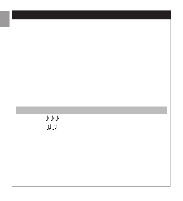
You can check whether any transmitters have been previously memorized in
the receiver; this is done by counting the number of beeps emitted when
the receiver is switched on.
Two different procedures can be followed to memorize the transmitters:
–Mode I: simplified memorization (the transmitter keys are automatically
configured by the RC1 receiver).
–Mode II: advanced memorization (each single transmitter key can be
configured for a specific command).
Checking the memorized transmitters
3 short beeps There are previously memorized transmitters
2 long beeps
No memorized transmitters
MEMORIZATION OF RADIO TRANSMITTERS
English – 5
EN
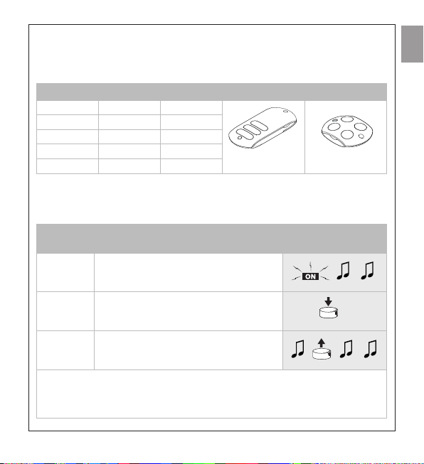
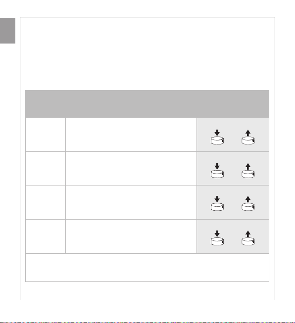
Memorizing the transmitters in Mode I (simplified memorization) Key s
(1) can perform the “Ascent” command, key n(2) performs the Stop com-
mand, whereas key t(3) can perform the “Descent” command; on trans-
mitter GTX4 key 4 performs the Stop command.
When there are no memorized transmitters you can proceed to program the
first transmitter in Mode I as shown in table [A].
Table [A] Memorizing the first transmitter in
Mode I
Example
1 Power the RC1 receiver: you will hear
two long beeps
2 Within 5 seconds press any key on the
radio transmitter to be memorized and
hold it down
3 Release the key when you hear the first
of the 3 beeps confirming memorisation
If the receiver has already memorized one or more transmitters, 3 short beeps
will be heard when it is switched on. In this case you will not be able to proceed
as described above, but will have to switch to the memorization mode described
in Table [B]
5s
Functions of the transmitter keys in Mode I
STX1 GTX4 Command
STX1 GTX4
Key sKey 1 Ascent
Key nKey 2 Stop
Key tKey 3 Descent
Key 4 Stop
6– English
EN
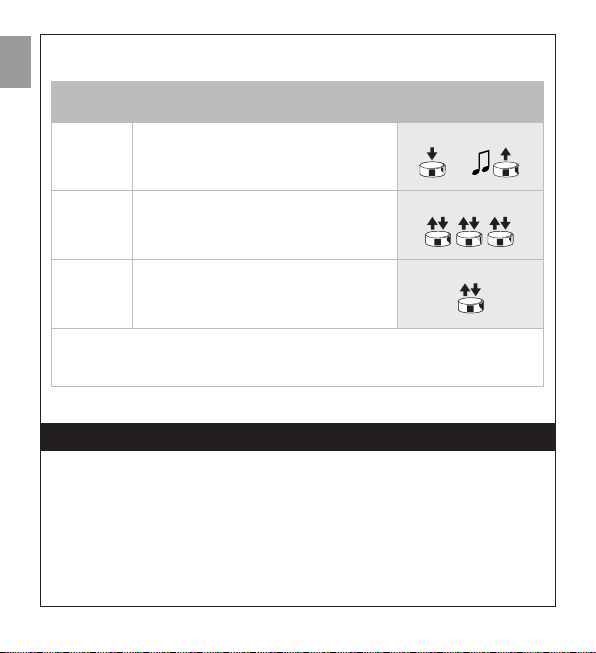
Even if one or more transmitters have already been memorized in Mode I,
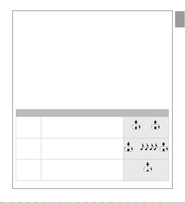
additional transmitters can be memorized in Mode I, as described in Table [B].
Table [B] Memorizing additional transmitters
in Mode I Example
1Press and hold down key nof the new
transmitter to be memorized (New TX)
until you hear a beep (after about 5
seconds) then release i
New TX
2Press key nof a previously memorized
transmitter (old TX) slowly 3 times Old TX
3 Once again, press and release the key on
the new transmitter you pressed
according to step 1
New TX
The 3 final beeps signal that the new transmitter has been correctly memorized.
If the memory is full (30 transmitters), 6 beeps will signal that the memory is not
capable of memorizing any additional transmitters.
5s
ADDITIONAL INFORMATION
—STEP 6 —
This chapter examines the various memorisation possibilities of the RC1
receiver 1.
Memorization in Mode II (advanced memorization)
In this mode, one of the 4 available commands can be associated to each
transmitter key, as shown in Table [C].
In this mode, the memorization procedure is performed separately for each
single transmitter key; this means that 2 keys on the same transmitter can be

English – 7
EN
memorized for two commands to the same receiver, or to command different
receivers as illustrated in the example below:
Group commands can be created using special memorisation processes, as
shown in figure 14:
• T1 memorised in Mode I both on A1 and A2 will enable the user to control
ascent, stop or descent simultaneously, both for A1 and A2.
• T2 memorised in Mode I on A3 only, makes it possible to control ascent,
stop or descent.
Table [C] Commands available for memorization Mode II
No. Command Description
1Step-By-Step The first command activates the ascent; whilst
the motor is actually moving, the second will
control the stop; the third controls descent,
and so on
2Ascent-Stop The first command activates the ascent; whilst
the motor is actually moving, the second will
control the stop
3Descent-Stop The first command activates the descent;
whilst the motor is actually moving, the second
will control the stop
4 Stop Activates the stop, and only the stop
Example of memorization in Mode II
Key 1 Awning
No. 1 Ascent
Key 2 Awning
No. 1 Descent
Key 3 Rolling shutter No.
1 Step-By-Step
Key 4 Rolling shutter No.
2 Step-By-Step

8– English
EN
• T3 memorised in Mode I on A4 only, makes it possible to control ascent,
stop or descent.
• T4 memorised in Mode II for the Step-By Step command on all the automa-
tions makes it possible to control the ascent or descent of A1 and A2 si-
multaneously, or control A3 or A4 separately; lastly, it will enable the user to
control the opening of the A5 automatic gate.
To memorize the transmitters in Mode II, refer to Tables [D] and [E].
Table [D] Memorizing the first transmitter
in Mode II Example
1 As soon as the receiver is powered, 2
long beeps will sound
2 Within 5 seconds, press the desired key
on the transmitter to be memorized and
hold it down until all 3 beeps have
sounded, then release the key
3 Within 3 seconds, press the same key on
the transmitter as many times as the
number corresponding to the desired
command: 1 = Step-By-Step; 2 = Ascent;
3 = Descent; 4 = Stop
4 After approx. 3 seconds you will hear a
number of beeps corresponding to the
selected command
5 Within 2 seconds, press and release the
same key to confirm the programming
The 3 final beeps signal that the new transmitter has been correctly memorized.
During step 4, if you do not hear the number of beeps corresponding to the
desired function, wait 10 seconds before abandoning the procedure, then try
again.
X1...X4
X1...X4

English – 9
EN
Table [E] Memorizing additional transmitters in
Mode II Example
1 Press and hold down the desired key on
the new transmitter (New TX) until you
hear a beep (after about 5 seconds) then
release it
New TX
2Within 5 seconds, press and hold down
for approx. 5 seconds a previously
memorized key on a transmitter (old TX)
until you hear 2 short beeps, then release
the key
Old TX
3Within 3 seconds, press again the same
key on the previously memorized
transmitter (old TX) as many times as the
number corresponding to the desired
command: 1 = Step-By-Step; 2 = Open;
3 = Close; 4 = Stop
Old TX
4 After approx. 3 seconds you will hear a
number of beeps corresponding to the
selected command
5Within 2 seconds, press again the
desired key on the new transmitter (new
TX) to confirm the programming
New TX
The 3 final beeps signal that the new transmitter has been correctly memorized.
If the memory is full (30 transmitters), 6 beeps will signal that the memory is not
capable of memorizing any additional transmitters.
5s
5s
X1...X4
X1...X4
10 – English
EN
Memorizing a new transmitter like a previously memorized transmitter
It is possible to memorize a new transmitter so that it operates exactly like a
previously memorized one. If the old transmitter was memorized in Mode I, the
new one will also operate in Mode I and a single memorization stage will be
required. If the key on the old transmitter was memorized in Mode II, also the
key on the new transmitter will be memorized in Mode II and will perform the
same function. If you wish to memorize more than one key you will have to
perform a memorization procedure for each key.
Table [F] Memorizing a new transmitter exactly
like a previously memorized
transmitter
Example
1 Press the key on the new transmitter
(new TX) to be memorized and hold it
down for at least 3 seconds, then release
it
New TX
2 Press the key on the previously
memorized transmitter (old TX) and hold
it down for at least 3 seconds, then
release it
Old TX
3 Press the key on the new transmitter
(new TX) again and hold it down for at
least 3 seconds, then release it
New TX
4 Press the key on the previously
memorized transmitter (old TX) and hold
it down for at least 3 seconds, then
release it
Old TX
The 3 final beeps signal that the new transmitter has been correctly memorized.
If the memory is full (30 transmitters), 6 beeps will signal that the memory is not
capable of memorizing any additional transmitters.
3s
3s
3s
3s
English – 11
EN
Programming the working time
The “Working Time” is the time during which the RC1 receiver commands
the motor for the “Ascent” sand “Descent” tmanoeuvres, and both the
factory time and the time after the memory has been deleted are approxi-
mately 150 seconds. If necessary, the running time can be altered from a
minimum of 4 seconds to a maximum of 250. The programming procedure
is carried out in the “self-recognition” state, or better, by measuring the time
necessary to carry out the entire manoeuvre. The motor must be moved and
set next to a limit switch and the most difficult (and therefore slowest) ma-
noeuvre for the motor measured. This is normally re-winding. The manufac-
turer recommends that users programme a working time which is a few
seconds longer than the time which is strictly necessary for the manoeuvre.
Moreover, considering that the manoeuvre in which the measurements are
taken begins in the opposite direction to the last manoeuvre carried out, be-
fore starting programming it is worth moving the motor to the limit switch
position of the least difficult manoeuvre.
A transmitter memorised in Mode I is necessary for programming, then follow
the steps described in the table below.
Table [G] Programming the working time Example
1Press and hold down key nof a
previously memorized transmitter until
you hear a beep (after about 5 seconds)
then release it
2Press again key nuntil you hear 4 short
beeps (after approx. 5 seconds), then
release
3Press skey (or tkey) in order to begin
the manoeuvre and start up the time
counting phase
5s
5s

12 – English
EN
Deleting the Receiver Memory
There may be cases when the RC1 receiver memory has to be deleted.
The memory can be deleted:
– using a non-memorised transmitter starting from point A.
– using a previously memorised transmitter starting the procedure from point
N. 1.
• Follow the procedure pressing the keys as shown if the transmitter has been
memorised in Mode I,
• Follow the procedure pressing the same key only, but only if it has been
previously memorised, if the transmitter has been memorised in Mode II.
The following items may be erased:
– Transmitters only, proceeding up to step 4
– All the data (transmitters and working time), completing the procedure up
to step 5.
4 Wait for the motor to finish the manoeuvre
(when it stops in the limit switch position)
and after a few seconds press key nto
stop the time count
The 3 final beeps signal that the new working time has been correctly memo-
rized. If the user wishes to reset the factory time of 150 seconds, at point 3 s/he
must press key nuntil s/he hears the first of 3 beeps indicating programming has
taken place.
Table [H] Deleting the memory Example
ËAWith the receiver not
powered, remove the
jumper from the board
(after clearing the
memory, the jumper
must be reinstalled)

English – 13
EN
B Power the receiver and wait for the initial
beeps
Ë1• With the transmitter in mode I or not
memorized: Press and hold down key n
(or 2) of the transmitter until you hear a
beep (after about 5 seconds) then release
it.
• With the transmitter in mode II: Press
and release the memorized key.
If the motor should start moving, press
the key again and hold it down until you
hear a beep (after about 5 seconds), then
release it
2After 1 second, press the skey and
release it precisely during the third beep
3After 1 second, press the nkey and
release it precisely during the third beep
4After 1 second, press the tkey and
release it precisely during the third beep
5 If you wish to completely erase all the data
stored in the memory, press keys sand
tsimultaneously within 2 seconds and
then release it
After a few seconds, 5 beeps will signal
that the memory has been cleared
Ë
Ë
5s
?... 5s
14 – English
EN
—STEP 7 —
The system needs no particular maintenance. This product is made up of dif-
ferent materials, some of which can be recycled, while others must be dis-
posed of. Enquire about the recycling or disposal systems available in
compliance regulations locally in force.
Warning: certain electronic components may contain polluting substances;
do not pollute the environment.
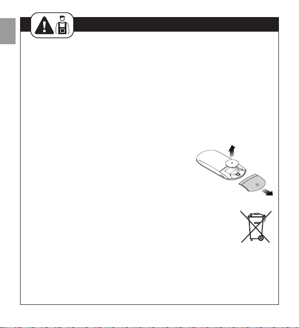
Replacing the Transmitter Battery
If the range of the transmitter is significantly diminished and the light emitted
by the LED is feeble, the remote control battery is probably exhausted. The
transmitter houses two CR2016 type lithium batteries.
To replace these batteries, you must:
1To open, pull the base as shown in the figure
alongside.
2Insert a pointed tool in the slot and push the bat-
teries outwards.
3Put the new batteries in, making sure the polarities
are correct (“+” towards the side where the keys
are).
4Close the bottom until it clicks.
WARNING: The batteries of the transmitter contain pollutants. do
not dispose of them together with other waste but use the meth-
ods established by local regulations.
MAINTENANCE AND DISPOSAL

English – 15
EN
TECHNICAL CHARACTERISTICS
RT3N is produced by NICE S.p.a. (TV) I, MHOUSE is an affiliate of the Nice S.p.a
group. Nice S.p.a., in order to improve its products, reserves the right to modify
their technical characteristics at any time without prior notice. In any case, the
manufacturer guarantees their functionality and fitness for the intended pur-
poses. Note: all technical specifications refer to a temperature of 20°C.
RC1 Receiver
Type Radio receiver for control of the
automation of awnings, rolling shutters
and similar fixtures
Adopted technology Reception and decoding of the radio
signals emitted by the transmitters.
Activation of the output relays only in
case of correspondence with a
previously memorized code, correctly
synchronized with the variability
sequence
Possibility of transmitter With GTX4 or STX1 transmitters
Coding Rolling code with 64 Bit code (18
billion million combinations)
GTX4 transmitter memorization
capacity Up to 30 if memorized in mode 1
Receiving frequency 433.92 Mhz
Receiver sensitivity Better than 0.6µV (with direct
coupling)
Range of STX1 transmitters Estimated as being 50-100m (the range
can vary in presence of obstacles
and electromagnetic disturbance)
Power supply 230Vac (+10 –15%) 50Hz

16 – English
EN
Maximum motor power 500W / 400VA
Absorption during standby <0.7W (typical 230Vac)
Activation time Approx. 300ms
Deactivation time Approx. 300ms
Will the transmitter continue to
function in case of blackout No
Precision of the working time 1s/±2%
Operating temperature -10 ÷ 55°C
Suitable for use in acid, saline or
potentially explosive atmospheres No
Protection Class IP55 (container undamaged), with
round cables with a diameter of 6.5 to
8.5mm
Dimensions and weight 98 x 26 x h 20mm / 45g

English – 17
EN
Transmitter STX1
Type Radio transmitters for automations for
awnings, rolling-shutters and similar
devices
Adopted technology AM OOK coded modulation of radio
carrier
Frequency 433.92 Mhz
Coding Rolling code con codice a 64 Bit (18
miliardi di miliardi di combinazioni)
Keys 3, each key can be used for the
different controls of the same receiver
or to control different receivers
Irradiated power Approx. 0.0001W
Power supply 6V +20% -40% with two CR2016
type lithium batteries
Battery life 3 years, estimated on the basis of 10
commands/day, each lasting 1s at
20°C (at low temperatures, the
efficiency of the batteries decreases)
Operating ambient temperature -20 ÷ 55°C
Suitable for use in acid, saline or
potentially explosive atmospheres No
Protection Class IP40 (suitable for use indoors or in
protected environments)
Dimensions and weight 720 x 31 x h 11mm / 18g
18 – English
EN
CE DECLARATION OF CONFORMITY
Declaration in accordance with Directive 1999/5/EC
RT3N is produced by Nice S.p.a. (TV) I; MHOUSE is a commercial trademark
owned by Nice S.p.a.
Note: The contents of this declaration correspond to declarations in the official document deposited
at the registered offices of Nice S.p.a. and in particular to the last revision available before printing
this manual. The text herein has been re-edited for editorial purposes.
A copy of the original declaration can be requested from Nice S.p.a. (TV) I.
Number: 190/RC1 Revision: 2 Language: EN
The undersigned, Luigi Paro, in the role of Managing Director, declares under
his sole responsibility, that the product:
Manufacturer’s Name: NICE S.p.a.
Address: Via Pezza Alta 13, 31046 Z.I. Rustignè - ODERZO -
ITALY
Model / Type: Receiver RC1, Transmitter STX1
Accessories:
Conforms to the essential requirements stated in article 3 of the following EC
directive, for the intended use of products:
• Directive 1999/5/EC OF THE EUROPEAN PARLIAMENT AND COUNCIL of 9
March 1999 regarding radio equipment and telecommunications terminal
equipment and the mutual recognition of their conformity according to the
following harmonised standards:
· Health protection (art. 3(1)(a)): EN 50371:2002
· Electrical safety (art. 3(1)(a)): EN 60950-1:2006+A11:2009
· Electromagnetic compatibility (art. 3(1)(b)): EN 301 489-1 V1.8.1:2008;
EN 301 489-3 V1.4.1:2002
· Radio spectrum (art. 3(2)): EN 300 220-2 V2.3.1:2010
In accordance with the directive 1999/5/EC (appendix V), the product is class 1
and marked:
Oderzo, 11 febbraio 2011 Ing. Luigi Paro
(Managing Director)
0682
Table of contents
Languages:
Other Mhouse Remote Control manuals


Popular Remote Control manuals by other brands

Philips
Philips SRP9348D/27 user manual

Velleman
Velleman CTC1000RC user manual

Mitsubishi Electric
Mitsubishi Electric Ecodan PAR-WT50R-E Operation manual

Flying Industry Development
Flying Industry Development S1F2-DC06 quick guide

Motorola
Motorola SRC-300 quick start guide

CAME
CAME ATOMO Series quick start guide


urmet domus
urmet domus 1051/035 Installation, programming and functions manual

Fujitsu
Fujitsu UTY-RNRYZ1 operating manual

Sony
Sony RM-AV2100B Operating Instructions (primary... operating instructions

Allo RemoteControl
Allo RemoteControl PROGET ETY 433 4N instructions

Fetch
Fetch Remote 3 user guide

CaryMart
CaryMart 12S1UB-DC12+1CV-12 user manual