Mhouse MhouseKit RME User guide

MhouseKit RME - RME Start
Kit with radio remote control for
automation of roller shutters, awnings,
and solar screens
Instructions and warnings for installation and
operation
Kit con radiocomando per
l’automazione di tapparelle, tende da
sole e schermi solari
Istruzioni ed avvertenze per l’installazione e l’uso
Kit avec radiocommande pour
l’automatisation de volets roulants,
stores externes et stores internes
Instructions et avertissements pour l’installation
Kit mit Fernsteuerung für die
Automatisierung von Rollläden,
Markisen und Sonnenschutzbehängen
Anweisungen und Hinweise für die Installation und die
Bedienung
Kit con radiomando para la
automatización de persianas, toldos y
pantallas solares
Instrucciones y advertencias para la instalación y el uso
Set met radiobesturing
voor het automatiseren van rolluiken,
zonneschermen en screens
Aanwijzingen en aanbevelingen voor installatie en gebruik
89.029/MH Rev.01 del 01-09-2004

2Instructions RME
English
•This handbook contains important safety instructions concerning installation procedures. Warning: incorrect installation can result in serious injuries;
it is essential to comply fully with all the following installation instructions.
•Kits with RME series tubular motors are designed for the automation of rolling systems such as roller shutters, awnings, and solar screens; all alter-
native uses are considered to be improper and are consequently prohibited. Mhouse shall not be held liable for damage resulting from improper use
of the product other than the use specified in this manual.
•Before starting the installation process check whether the tubular motor and accessories are suitable for the application, paying particular attention
to the data given in the "Technical Specifications" chapter. When choosing the type of motor in relation to the application, consider the nominal torque
and operating time given in the rating data. The motors are designed for use in residential applications with a 20% duty cycle; this means, for exam-
ple, that a 1 minute operating cycle must be followed by a minimum pause of 5 minutes. The maximum continuous operating time is 4 minutes.
•The minimum diameter of the tube in which the motor can be accommodated is 52 mm.
•Installation work must be executed in full compliance with applicable safety regulations. Before installing the product remove all electrical cables
except those that are required for the system; all mechanisms not specifically required for motorized operation of the system must be deactivated.
•The minimum installation height is 2.5 m; ready access to the automation must be assured at all times. In the case of awnings, the horizontal dis-
tance between the fully open awning and any immoveable obstructions must be at least 0.4 m.
•The power cable with PVC insulation supplied with the RME unit is suitable for indoor installation; for exterior use the entire length of the cable must
be protected by routing it through an insulating conduit.
•At the time of installation and when using the system ensure the tubular motor is not subjected to crushing, impact, dropping or contact with any
type of liquid. Do not pierce or fix screws at any point of the length of the tubular motor. Do not install the motor close to intensive heat sources or
expose it to naked flames. Any of the foregoing situations can result in serious damage to the tubular motor and give rise to operating faults and/or
potentially hazardous conditions. If any of the above situations occurs, stop using the system immediately and contact the Mhouse service organi-
sation.
•All installation and maintenance operations must be performed with the system disconnected from the power supply; if the disconnection device is
not clearly visible from the place of work, affix a notice to the effect: "WARNING: MAINTENANCE WORK IN PROGRESS".
•Installation and electrical hook-up operations must be performed by a licensed electrician in full compliance with safety regulations.
•The packing materials must be disposed of in compliance with local regulations.
1 Installation warnings
In 15, 30 or 45Nm torque versions "RME" series tubular motors (figure 1)
with Ø 45 mm tube are electric motors equipped with reduction gear unit
designed for use in the automation of rolling systems such as: roller shut-
ters, awnings, and solar screens.
The tubular motor complete with the specific adapters is installed by
inserting it inside the system's roller tube; in this position the motor can
drive the system by causing the tube to rotate in either direction.
RME tubular motors contain an electronic controller with a high-precision
electronic stroke limiting system able to monitor the position of the shut-
ter, awning or solar screen continuously. The stroke limits of the system,
i.e. the positions with the fixture completely closed and fixture complete-
ly opened, plus an optional intermediate position, are stored in an inter-
nal memory by means of a programming procedure. Once the system
has been programmed, each command relayed via the transmitter will
cause the motor to start a cycle and stop automatically when the preset
position has been reached. While the motor is running the controller mon-
itors torque conditions constantly and interrupts the movement immedi-
ately if it detects sudden changes in torque such as would result if the
shutter or awning encounters an obstacle.
RME tubular motors contain a radio receiver operating at 433.92MHz.
The radio system utilizes rolling code technology that makes it possible
to control the motor from a remote location while ensuring the maximum
levels of security.
Up to a maximum of 30 transmitters can be stored for the control of each
motor. Kits with RME tubular motors are available in versions with a TX3
transmitter supplied as standard (RME) or without the transmitter (RME
Start); in this second case you will need to purchase at least one Mhouse
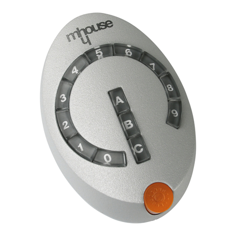
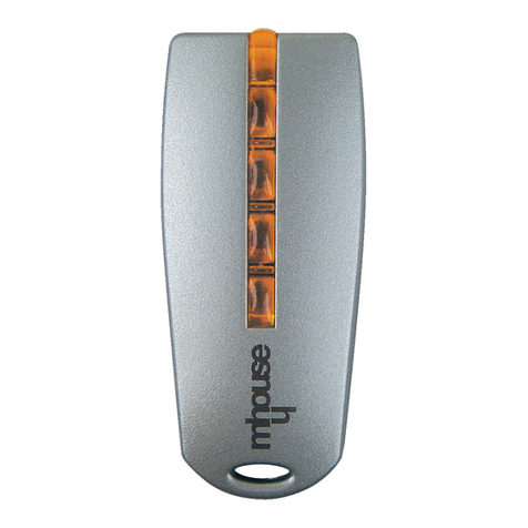
transmitter type TX3 (figure 2) or TX4 (figure 2).
The TX3 transmitter has a support in order that it can be mounted, to a
wall for example. Adhesive tape can be used if the surface is smooth and
solid, otherwise the special screw and screw anchor supplied
RME is supplied complete with a support, code AR1, and an adapter,
code AR4, suitable for use with 60 mm diameter octagonal tubes (the
type of tube commonly utilized by rolling shutter manufacturers). Alterna-
tively, order kits with support AR2 and adapters AR3 and AR5 for cigar-
shaped tubes, diameter 78 and 70 mm respectively (these tubes are
commonly utilized by awning manufacturers).
RME
Fig. 1
TX3 TX4
Fig. 2
2 Product description and intended use
Fig. 3

Instructions RME 3
English
Before starting the installation work check that you have all the necessary material. Specifically, check that the support is suitable in relation to the fix-
ing surface and that you have the correct adapters in relation to the type of roller tube.
1. On the basis of table 1 (for roller shutters) or 2 (for awnings) check that the motor has been correctly selected in relation to the characteristics of
the roller system.
•Roller shutters: the choice of motor depends on the weight of the shutter. With a Ø60 mm roller tube RME15 is able to raise shutters weigh-
ing up to 28 kg; RME30 up to 56 kg, and RME45 up to 90 kg. Table 1 allows you to choose the type of motor in relation to the surface area of
the shutter and its construction material.
•Awnings: the choice of the type of motor is to be made on the basis of the force required to close the awning. Table 2 allows you to choose
the type of motor in relation to the diameter of the tube, the number of folding arms, and the extension of the awning when fully open.
2. Fix support [C] shown in figure 4 securely; note that you must leave sufficient space for the motor head between the support and the roller tube.
3. Prepare the motor as follows:
•Fit limit switch ring [E] over motor [A] and slide it down until it interlocks with corresponding ringnut [F].
•Fit drive wheel [D] onto the motor shaft
•Secure the drive wheel with the circlip
4. Insert the thus-assembled motor into the roller tube until limit switch ring [E] is pressed fully home.
5. Secure drive wheel [D] to the roller tube by means of an M4x10 screw in such a way as to prevent axial movement of the motor (figure 5).
Ensure that the screw is perfectly centred with respect to drive wheel [D] and, before drilling the hole for the screw, measure the position at which
the wheel will be located once the motor has been inserted in the roller tube.
6. Insert the motor and secure motor head to previously fixed support [C] by means of clips [B].
7. Insert the power supply cable through the conduit until reaching the electrical connection box. Check that the power cable cannot become entan-
gled when the roller mechanism is moving.
(with Ø 60mm roller tube)
Material:
Wood
PVC
Aluminium
Maximum surface area of shutter (m2)
Up to 2,8 Up to 5 Up to 5,6 Up to 9 Up to 10 Up to 16
RME15 RME30 RME45 - - - -
RME15 RME30 RME45
Table [1] Roller shutters: motor torque in relation to shutter material and surface area
3 Installation
Tube diameter:
Awning extension
No. of arms:
1,5 m
2 m
2,5 m
3 m
4 m
5 m
70 mm 78 mm
2424
RME15
RME30
RME45
RME30
RME45
RME30
RME45
-- -- --
RME45
RME15 RME30
Table [2] Awnings: motor torque according to no. of arms and awning extension
Fig. 4
Fig. 5
A
C
D
E
F
B

4Instructions RME
English
In "RME" tubular motor kits the supplied TX3 transmitter is already stored in the memory and ready to operate.
When using "RME Start" kits you need to purchase at least one Mhouse transmitter type TX3 or TX4 and then store it in the system memory as descri-
bed in table 3.
After storing a transmitter (in Mode I) the transmitter keys will transmit the
commands described in table 4.
Note: until the limit positions have been programmed the motor operates
in "operator present" mode, i.e. it runs only as long as the transmitter key
is pressed; in these conditions commands ▲ and ▼can be inverted so
that they have the opposite effect.
Additional information and alternative methods for storing trans-
mitters are given in the "Details" section.
5 Storing the transmitter in the system memory
RME tubular motors are equipped with a controller with an electronic lim-
iter system that stops the movement when the motor reaches the pro-
grammed positions, i.e. the positions with the system completely retract-
ed or the position with the system completely extended. In addition to the
two end positions it is also possible to program an intermediate position,
which can be used, for example, for partial opening of a shutter.
These positions must be stored in the memory with a specific program-
ming procedure that is carried out with the motor installed and the shut-
ter, awning or solar screen mounted.
For the sake of simplicity, the expressions: “roller up", "roller down" and
"intermediate position" have been replaced by the terms "position 0"
(roller up); "position 1" (roller down); and "position I (intermediate), corre-
sponding to the positions shown in figure 7 (for shutters) and figure 8 (for
awnings).
6 Programming the limit positions
Table [4] Transmitter key functions (Mode I)
TX3 TX4 Command
Key ▲Key T1 Raise
Key ■Key T2 Stop
Key ▼Key T3 Lower
Key T4 Stop TX3 TX4
Pressing keys ▲ and ▼together (T1 and T3) causes the shutter or awning
to move to intermediate position "I"
Table [3] Storing the first transmitter (in Mode I) Example
1Connect the RME to the power supply; it will emit 2 long beeps
2Within 5 seconds press and hold down any key on the transmitter you wish to store in the automation memory
3Release the key when you hear the first of the 3 beeps that are emitted to confirm that the transmitter has
been stored in the memory
If 3 short beeps are emitted when you connect the power supply this indicates that the RME system already contains transmitters in the memory; in this case
you cannot store transmitters as described above – instead, adopt the procedure described in table 9
5s
Shutter open
(Position "0")
Shutter closed
(Position "1")
Intermediate
position "I"
Fig. 7
Awning closed
(Position "0")
Awning open
(Position "1")
Intermediate
position "I"
Fig. 8
4 Electrical connections
WARNING: the electrical power supply line must be equipped with a
device to protect against short circuits. In addition, a disconnect device
must be installed (with overvoltage category III, i.e. with minimum contact
gap of 3.5 mm) or an alternative equivalent system, such as a plug and
socket connection. Once the installation is terminated, the power supply
disconnection device must be readily accessible and, if it is not located in
the immediate vicinity of the automation it must be equipped with a lock-
out system to prevent unintentional or unauthorised reconnection.
"RME" series tubular motors must be constantly powered by means of a
permanent connection to the 230V mains circuit.
The motor electrical connections are shown in figure 6.
WARNING: make the connections exactly as indicated; in case of doubt
do not proceed by trial and error: seek assistance from the Mhouse serv-
ice organisation or consult the specific detailed technical datasheets,
which can be downloaded from the Internet site www.mhouse.biz. Incor-
rect electrical connections can cause serious faults and dangerous con-
ditions.
Yellow/green wire = : Safety grounding system
Brown wire = L : Phase for 230V supply
Blue wire = N : Neutral for 230V supply
Fig. 6
T4
T3
T2
T1

Instructions RME 5
English
1. Press key ▲ or ▼on the transmitter until the roller mechanism is in the required "0" position,
then release the key.
2. Press transmitter key ■and hold it down until the motor emits a beep (after approx. 5 seconds);
release the key.
3. Press transmitter key ■again and hold it down until you hear 4 short beeps (after approx. 5 seconds);
release the key.
4. Press key ▲and hold it down until 3 beeps and a brief movement indicate that position "0" has been
stored in the memory
5. Press key ▲ or ▼on the transmitter until the roller mechanism is in the required "1" position, then
release the key.
6. Press transmitter key ■and hold it down until the motor emits a beep (after approx. 5 seconds);
release the key.
7. Press transmitter key ■again and hold it down until you hear 4 short beeps (after approx. 5 seconds);
release the key. 5s
8. Press key ▼and hold it down until 3 beeps and a brief movement indicate that position "1" has been
stored in the memory.
When the programming procedure is terminated the motor is fully operational and key ▲on the transmitter handset should generate movement towards
position "0" while key ▼generates movement towards position "1".
Table [5] Programming positions "0" and "1" Example
WARNING: until both positions "0" and "1" have been stored the motor
functions in "man present" mode, i.e. it runs only as long as the trans-
mitter key is pressed.
If you subsequently wish to change positions "0" and "1" the original set-
tings must first be deleted and then the programming phase can be
repeated. To delete all positions ("0", "1" and "I") execute steps 2, 3 and
4 (the unit will emit 5 beeps at point 4).
In addition to positions "0" and "1", which are necessary for operation of
the motor, you can also program a third optional position, defined as
"Intermediate"; this position can be used, for example, for partial opening
of a shutter.
The intermediate position can be set at any point between positions "0"
and "1", but only after these two limit positions have already been pro-
grammed.
If you wish to modify the chosen "I" position at a later date, the "I" posi-
tion programming procedure must be repeated twice in succession: the
first time serves to delete the current position (you can start from point 2
and you will hear 5 beeps at point 4 confirming that the position has been
deleted) and the second time serves to program the new "I" position.
Additional information and alternative programming methods are
given in the "Details" section.
1. Press transmitter key ▲ or ▼to control the roller and press key ■to stop it in the required intermediate
position "I"
2. Press transmitter key ■and hold it down until the motor emits a beep (after approx. 5 seconds);
release the key.
3. Press transmitter key ■again and hold it down until you hear 4 short beeps (after approx. 5 seconds);
release the key.
4. Press keys ▲and ▼together and keep them pressed until you hear 3 beeps indicating that position "I"
has been stored
The intermediate position movement command is obtained by pressing transmitter keys ▲and ▼together; this command can be given irrespective of the
current position of the roller system..
Table [6] Programming of intermediate position "I" Example
7 Operating warnings
•This handbook contains important safety instructions. Warning: for the
purposes of personal safety it is essential to observe these instructions
and to keep this handbook so that it can be readily consulted in the future
•Do not allow minors to play with the control devices; keep the remote
handset out of reach of children.
•Inspect the automation regularly to check for signs of wear, damage, or
imbalance. Stop using the automation immediately if it needs servicing.
•Monitor the automation during the movement and prevent any persons
from approaching until the movement is concluded.
•Do not transmit movement commands if there are persons in the imme-
diate vicinity of the automation involved in operations such as window
cleaning, etc.; the electrical power supply must be disconnected before
work is performed in the immediate vicinity of the automation.
5s
5s
+
No special maintenance operations are necessary for RME series tubular
motors. For any repairs or replacements, to avoid all possible risks always
refer to the Mhouse service organisation (e.g. for the replacement of the
power cable if the existing cable is damaged). This product is made from
various types of materials, some of which can be recycled while others
must be disposed of. Make sure you recycle or dispose of the product in
compliance with laws and regulations in force locally.
WARNING: certain electronic components may contain pollutants: do not
pollute the environment.
Changing the transmitter batteries
When the operating range of the transmitter is reduced significantly and
the light emitted by the LED becomes dim, it is likely that the batteries are
drained. The transmitter contains two CR2016 lithium batteries; to
change the batteries:
1. Open the base by pulling as shown in figure 9.
2. Insert a small non-metallic pointed tool in the slot as shown in figure
10 and force the batteries out.
3. Fit the new batteries observing the correct polarity (the "+" side must
face the side of the handset with the keys).
4. Slide back the base until it clicks into place.
Warning: The transmitter batteries contain pollutants: do not dispose of
batteries in normal urban waste. Use the methods of disposal prescribed
by the relevant local bylaws.
8 Maintenance and Disposal
Fig. 9 Fig. 10
5s
5s
5s
5s

6Instructions RME
English
This chapter describes other methods of storing transmitters in order to obtain dif-
ferent control functions, plus additional programming facilities.
Storing transmitters
There are 2 methods of storing transmitters:
•Mode I: simple storage (each transmitter key transmits a preset command, see
table 4)
•Mode II: advanced storage (each transmitter key is programmed for a specific
command, see table 7)
Further details concerning Mode II storage are given in the heading: "Mode II
programming characteristics"
•For information on storing the first transmitter in Mode I, refer to table 3
•For the storage of additional transmitters in Mode I, refer to table 9
•For information on storing the first transmitter in Mode II, refer to table 10
•For the storage of additional transmitters in Mode II, refer to table 11
•For the storage of additional transmitters in the same Mode as a transmitter that
has already been stored, refer to table 12
•To clear the automation memory (including all transmitters) refer to table 13
WARNING: programming via radio will affect all motors present within range of the
transmitter; therefore ensure that only the motor you wish to program is connect-
ed to the power supply when performing the programming operation.
9 Details
Mode II programming characteristics
WARNING: transmitters that have been stored in the automation memory using Mode II can be used to control the motor but they cannot be used to program limit posi-
tions or clear the memory.
In Mode II the storage procedure is performed separately for each individual transmitter key; it follows that two keys on the same transmitter can be assigned to two
commands of the same motor or to control two different motors as indicated in the following example:
With appropriate storage procedures you can create group commands as in the
example shown in Fig. 11:
•T1 stored in Mode I both on A1 and A2 makes it possible to control raise, stop,
and lower commands simultaneously on A1 and A2
•T2 stored in Mode I only on A3 makes it possible to control raise, stop, or low-
er functions
•T3 stored in Mode I only on A4 makes it possible to control raise, stop, or low-
er functions
•T4 stored in Mode II for the Step-by-Step control on all the automations makes
it possible to control A1 and A2 simultaneously, to control A3 or A4 separately,
and to control the opening of automatic gate A5.
Table [7] Commands available with Mode II memory storage
N° Command Description
1Step-by-Step The first command activates upward movement; the next command – with the motor running – activates a stop;
the third command activates a downward movement, and so forth
2Raise-Stop The first command activates upward movement; the next command – with the motor running – activates a stop
3Lower-Stop The first command activates downward movement; the next command – with the motor running – activates a stop
4Stop Activates exclusively a stop command in all circumstances
Table [8] Example of Mode II storage procedure
Key 1 Raise Awning No. 1
Key 2 Lower Awning No. 1
Key 3 Step-by-Step Shutter No. 1
Key 4 Step-by-Step Shutter No. 2
Fig. 11
Table [10] Storing the first transmitter in Mode II Example
1As soon as the motor is connected to the power supply the system will emit 2 long beeps
2Within 5 seconds press and hold down the required key on the transmitter to be stored until the end of all 3 beeps,
then release the key
3Within 3 seconds press the same key on the transmitter for a number of times equivalent to the required command as
follows: 1 = Step-by-Step; 2 = Raise; 3 = Lower; 4 = Stop
4After approximately 3 seconds you will hear a number of beeps equivalent to the chosen command
5Within 2 seconds press and release the same key to confirm the programming
The 3 final beeps signal that the new transmitter has been stored correctly. If you do not hear the same number of beeps as the selected command at point 4, wait 10
seconds to quit the procedure and then try again
X1...X4
X1...X4
Table [9] Storage of additional transmitters in Mode I Example
1Hold down key ■on the new transmitter to be stored (New TX) until you hear a beep (after approx. 5 seconds)
then release the key New TX
2Slowly press key ■three times on a transmitter that has already been stored in the memory (Old TX)
Old TX
3Press and release key ■on the new transmitter
New TX
The 3 final beeps indicate that the new transmitter has been stored correctly in the memory. If the memory is full (30 transmitters), the automation will emit 6 beeps to
signal that the transmitter cannot be stored.
5s

Instructions RME 7
English
Table [11] Storage of additional transmitters in Mode II Example
1Hold down the required key on the new transmitter (New TX) until you hear a beep (after approx. 5 seconds)
then release the key
New TX
2Within 5 seconds press and hold down a key that has already been stored on a transmitter (old TX) until hearing 2 short
beeps (after approx. 5 seconds) then release the key Old TX
3Within 3 seconds press the same key on the already stored transmitter (old TX) for a number of times equivalent to
the required command: 1 = Step-by-Step; 2 = Open; 3 = Close; 4 = Stop Old TX
4After approximately 3 seconds you will hear a number of beeps equivalent to the chosen command
5Within 2 seconds press the required key on the new transmitter (new TX) again to confirm the programming.
New TX
The 3 final beeps signal that the new transmitter has been stored correctly. If the memory is full (30 transmitters), the automation will emit 6 beeps to signal that the
transmitter cannot be stored.
5s
5s
X1...X4
X1...X4
Table [12] Memory storage of a new transmitter like an already stored transmitter Example
1Hold down the key on the new transmitter to be stored (New TX) for at least 3 seconds and then release it.
New TX
2Hold down the key on the already stored transmitter (old TX) for at least 3 seconds and then release it.
Old TX
3Hold down the key on the new transmitter again (New TX) for at least 3 seconds and then release it.
New TX
4Hold down the key on the already stored transmitter (old TX) for at least 3 seconds and then release it.
Old TX
The 3 final beeps signal that the new transmitter has been correctly stored. If the memory is full (30 transmitters), the automation will emit 6 beeps to signal that no
further transmitters can be stored in the memory.
Note: if the transmitter already stored has been programmed in Mode I, also the new transmitter will function in Mode I and a single storage phase will be sufficient. If
the key of the already stored transmitter is programmed in Mode II, also the key of the new transmitter will be programmed in Mode II and it will execute the same
command; if you wish to store other keys repeat the memory storage phase for each key.
3s
3s
3s
3s
Clearing the motor memory
In certain cases it may prove necessary to remove the programming functions
stored in the memory of the RME tubular motor.
The memory can be cleared with:
•anon-stored transmitter, starting from point A
•atransmitter that has already been stored, starting the procedure from point
No.1
The following can be deleted:
•transmitters only, terminating at point 4
•all data (transmitters and positions) completing the procedure up to point 5
WARNING: Memory clearing is not possible using a transmitter stored in Mode II
Table [13] Memory delete Example
AHold down key ■of a non-stored transmitter until you hear a beep
BWithin 5 seconds disconnect the power supply to the motor; wait for a few seconds and then power up the motor again.
Within 1 minute continue with the remainder of the deletion procedure, disregarding the fact that you would normally
need an already stored transmitter
1Hold down key ■on an already stored transmitter until you hear a beep (after approx. 5 seconds).
2Hold down key ▲on the transmitter until you hear 3 beeps; release key ▲precisely during the third beep.
3Hold down key ■on the transmitter until you hear 3 beeps; release key ■precisely during the third beep.
4Hold down key ▼on the transmitter until you hear 3 beeps; release key ▼precisely during the third beep.
5If you wish to delete all data in the memory, within 2 seconds press keys ▲and ▼together, then release the keys.
After a few seconds 5 beeps will sound to indicate that the memory has been cleared.
5s
➨
➨
➨
➨
2s
+
The red LED does not flash when a transmitter key is pressed.
Check also with the other keys then try changing the batteries.
The motor fails to emit any beeps immediately after it is connected to the
power supply.
Check to ensure that the motor is supplied with the correct mains voltage; if the
power supply is correct the motor is probably suffering from a serious fault.
After a command the motor fails to move.
•If the motor was functioning immediately beforehand the thermal overload cutout
may have tripped; in this case wait for a few minutes to give the motor time to cool
down.
•Check that there is at least one memorized transmitter by ensuring that the
motor emits 3 short beeps when it is powered.
•Check for the presence of "communication" between transmitter and motor by
holding down key ■(T2) on a transmitter (stored or not stored) for at least 5 sec-
onds; if you hear a beep this means that the motor is receiving the signal from
the transmitter – in this case go on to the final check; otherwise execute the next
check.
•Check for the correct emission of the radio signal from the transmitter by means
of the following empirical test: press a key and place the LED in contact with the
antenna of a normal radio receiver (preferably a low cost model) that is switched
on and tuned to 108.5Mhz or as close as possible on the FM band; the radio
should emit a regular pulsating buzzing noise.
•Press all the transmitter keys slowly one at a time; if none of the keys causes the
motor to move this indicates that the transmitter is not stored in the memory.
Following a radio command a few Beeps are emitted and the movement
fails to start.
The memory has been incorrectly programmed; count the number of beeps and
contact the Mhouse service organisation to obtain information on the method to
adopt to restore correct operation.
During the movement the motor stops before reaching the programmed
positions.
This is normal if the motor has detected excessive torque. Check for the presence
of obstacles obstructing the movement.
The motor moves only in "man present" mode.
If positions "0" and "1" have not been programmed, the up and down movement
of the motor can only occur while the operator continues to press the correspon-
ding keys. Perform the programming procedure as described in table 5.
For any other problems contact the Mhouse service organisation and describe the
type of fault in detail and all the checks you have already carried out.
10 What to do if... brief guide in the case of problems!

8Instructions RME
English
RME series tubular motors are manufactured by Nice S.p.a. (TV) I. The company Mhouse S.r.l. is a member of the same group as Nice S.p.a.
NICE S.p.a. observes a continuous improvement policy and reserves the right to modify the technical specifications at any time without notice. In such
cases specified functionality and intended use will not be affected.
Note: all technical specifications refer to a temperature of 20°C.
11 Technical Specifications
RME tubular motor RME15 RME30 RME45
Type Tubular geared motor for roller shutters, awnings and solar screens with built-in controller and radio receiver
Technology Asynchronous single-phase motor with 3-stage planetary gear unit; electronic type limit sensing
Power cable Length approx. 3 m, cable type H05VV-F (only for indoors use)
Power supply 230Vac (+10% -15%) 50Hz
Rated current 0,8A 1,3A 1,15A
Torque 15Nm 30Nm 45Nm
Weight lifted (with Ø60 mm roller) 28Kg 56Kg 90Kg
Speed 16 rpm 16 rpm 12 rpm
Maximum number of turns 43 43 30
Precision (resolution) of the electronic limit switch better than 0,5° better than 0,5° better than 0,4°
Continuous operating time 4 minutes maximum
Duty cycle Maximum 20% (for example, 1 minute of operation must be followed by a pause of at least 5 minutes)
Remote control facility With TX3 or TX4 transmitters
Transmitter encoding 64 bit rolling code (18 billion billion combinations)
Number of transmitters that can be stored Up to 30 (if stored in mode I)
Reception frequency 433.92 Mhz
Receiver sensitivity Better than 0.6µV (with direct coupling)
Transmitter range Estimated at 50-100m in optimal open field conditions; 20-30m indoors
(the range varies in the presence of obstacles and electromagnetic interference).
Environmental operating temperature -20 ÷ 55°C
Use in acidic, saline or potentially explosive
atmospheres No
Protection rating IP44
Dimensions / weight Tube Ø45 mm; length 570 mm, approx. weight 2700g
Transmitter TX3
Type: Radio transmitters for automations of awnings and roller shutters, etc.
Technology: Radio carrier AM OOK coded modulation
Frequency: 433.92 Mhz
Encoding: 64 bit rolling code (18 billion billion combinations)
Keys: 3, each key can be utilized for the various command functions of the same motor,
or to command different motors or automations that are compatible with the encoding
Irradiated power: approx 0.0001W
Power supply: 6V +20% –40% with 2 Lithium batteries type CR2016
Battery life: 3 years, estimated on the basis of 10 commands/day lasting 1s at 20°C
(battery efficiency falls at lower temperatures)
Environmental operating temperature: -20 ÷ 55°C
Use in acidic, saline or potentially explosive
atmosphere: No
Protection rating: IP40 (use in the home or protected environments)
Dimensions / weight: 720 x 31 h 11mm / 18g
CE declaration of conformity in accordance with Directives 73/23/EEC; 89/336/EEC and 1999/5/CE
RME15; RME 30; RME45 and TX3 are produced by NICE S.p.a. (TV) I; MHOUSE S.r.l. is a member of the Nice S.p.a. group.
Number: 191/RME Revision: 0
The undersigned Lauro Buoro, Managing Director, declares under his own responsibility that the product:
Manufacturer's name: NICE s.p.a.
Address: Via Pezza Alta 13, 31046 Z.I. Rustignè, Oderzo (TV) Italia
Type: Tubular geared motor for roller shutters, awnings and solar screens with integral controller and radio receiver
Models: RME15, RME30, RME45
Accessories: Radio remote control TX3 or TX4
Complies with the requirements of the following community directives as amended by Directive 93/68/EEC of the Council of 22 July 1993:
•73/23/EEC; DIRECTIVE 73/23/EEC OF THE COUNCIL of 19 February 1973 concerning the harmonisation of Member States' legislation relative to
electrical material destined to be used within specified voltage limits
•89/336/EEC: DIRECTIVE 89/336/EEC OF THE COUNCIL of 3 May 1989, for the harmonization of Member States' legislation concerning electro-
magnetic compatibility.
In addition, it complies with the basic requirements of article 3 of the following community directive, for the uses for which the products are designed:
•1999/5/EC; DIRECTIVE 1999/5/EC OF THE EUROPEAN PARLIAMENT OF THE COUNCIL of 9 March 1999 concerning radio equipment and tele-
communications terminal equipment and the reciprocal acknowledgement of their compliance.
Oderzo, 3 July 2004 Lauro Buoro
(Managing Director)
12 EC Declaration of Conformity

Italiano
Istruzioni RME 9
•Questo manuale contiene importanti istruzioni di sicurezza per l’installazione. Attenzione: l’installazione non corretta può causare gravi ferite; è impor-
tante rispettare tutte queste istruzioni per l’installazione.
•Ikit con motori tubolari della serie RME permettono di automatizzare il movimento di avvolgibili come tapparelle, tende da sole e schermi solari; ogni
altro uso è improprio e vietato. Mhouse non risponde dei danni risultanti da un uso improprio del prodotto, diverso da quanto previsto nel presente
manuale.
•Prima di iniziare l'installazione verificate se il motore tubolare e gli accessori sono adatti all'uso, con particolare attenzione ai dati riportati nel capito-
lo "Caratteristiche tecniche". Nella scelta del tipo di motore in funzione dell’applicazione, si dovrà considerare la coppia nominale ed il tempo di fun-
zionamento riportati sui dati di targa. I motori sono progettati per uso residenziale con un ciclo del 20%; cioè, ad esempio, dopo un ciclo di lavoro
di 1 minuto deve seguire una pausa di almeno 5 minuti; il tempo massimo di funzionamento continuo è 4 minuti.
•Il diametro minimo del tubo su cui il motore può essere installato è di 52mm.
•L’installazione deve essere eseguita nel pieno rispetto delle norme di sicurezza. Prima dell’installazione devono essere allontanati tutti i cavi elettrici
non necessari; tutti i meccanismi non necessari per il funzionamento motorizzato devono essere disattivati.
•L’altezza minima di installazione è 2,5m garantendo comunque un facile accesso. Nelle tende da sole, la distanza in orizzontale tra la tenda com-
pletamente aperta e qualsiasi oggetto permanente deve essere garantita ad almeno 0,4m.
•Il cavo di alimentazione in PVC in dotazione ad RME lo rende adatto ad essere installato all’interno; per uso esterno occorre proteggere tutto il cavo
con un tubo d’isolamento.
•Nell’installazione e durante l’uso fare attenzione a non sottoporre il motore tubolare a schiacciamenti, urti, cadute o contatto con liquidi di qualunque
natura; non forare né applicare viti per tutta la lunghezza del tubolare; non porre il motore vicino a forti fonti di calore né esporlo a fiamme; tutte que-
ste azioni possono danneggiarlo ed essere causa di malfunzionamenti o situazioni di pericolo. Qualora accada, sospendere immediatamente l'uso
e rivolgersi al servizio assistenza di Mhouse.
•Tutte le operazioni di installazione e manutenzione devono avvenire senza la presenza dell'alimentazione elettrica; se il dispositivo di sconnessione
non è a vista apporvi un cartello: "ATTENZIONE MANUTENZIONE IN CORSO".
•L’installazione e l’allacciamento elettrico deve essere eseguito da personale tecnico qualificato nel pieno rispetto delle norme di sicurezza.
•Il materiale dell'imballaggio deve essere smaltito nel pieno rispetto della normativa locale.
I motori tubolari della serie “RME” (figura 1) con tubo Ø 45 mm; nelle ver-
sioni con coppia da 15, 30 o 45Nm sono dei motori elettrici completi di
riduzione di giri che permettono di automatizzare il movimento di avvolgi-
bili come, ad esempio: tapparelle, tende da sole e schermi solari.
Il motore tubolare, completato con gli appositi adattatori, viene installato
inserendolo dentro al rullo avvolgitore dell’avvolgibile ed è in grado di
muoverlo svolgendolo e ritirandolo.
I motori tubolari RME contengono una centrale elettronica con un siste-
ma di finecorsa elettronico ad elevata precisione che è in grado di rileva-
re continuamente la posizione dell’avvolgibile. Attraverso una operazione
di programmazione vengono memorizzati i limiti del movimento, cioè le
posizioni di avvolgibile completamente ritirato e di avvolgibile completa-
mente srotolato; più una posizione intermedia opzionale. Dopo la pro-
grammazione, ogni comando col trasmettitore provoca il movimento e la
fermata automatica al raggiungimento della posizione prevista. Durante il
movimento del motore la centrale mantiene costantemente controllato lo
sforzo interrompendo subito il movimento in caso di brusca variazione
provocata, ad esempio, da un ostacolo.
I motori tubolari RME contengono un ricevitore radio sulla frequenza di
433,92MHz; in tecnologia rolling code che permette di comandare a
distanza il motore garantendo comunque i massimi livelli di sicurezza.
Per ogni motore è possibile memorizzare fino a 30 trasmettitori. I kit con
motori tubolari RME sono disponibili nelle versioni con un trasmettitore
TX3 di serie (RME) oppure senza (RME Start); in questo caso occorre
procurarsi almeno un trasmettitore Mhouse tipo TX3 (figura 2) oppure
TX4 (figura 2).
Il trasmettitore TX3 è dotato di un supporto per il fissaggio, ad esempio
a parete. Se la superficie di fissaggio è liscia e compatta può essere uti-
lizzato l’adesivo in dotazione; altrimenti occorre utilizzare l’apposita vite
ed eventualmente anche il tassello in dotazione.
La dotazione di RME comprende il supporto cod. AR1 e l’adattatore cod.
AR4 idoneo per tubi ottagonali da 60mm (solitamente impiegati nelle tap-
parelle). In alternativa sono disponibili i kit supporto AR2 e gli adattatori
AR3 ed AR5 per tubi ogiva, rispettivamente 78 e 70mm (solitamente
impiegati nelle tende da sole).
RME
Fig. 1
TX3 TX4
Fig. 2
1 Avvertenze per l’installazione
2 Descrizione del prodotto e destinazione d’uso
Fig. 3

Italiano
10 Istruzioni RME
Prima di procedere con l’installazione è fondamentale verificare di avere a disposizione tutto li materiale necessario; in particolare che il supporto sia
adatto alla superficie di fissaggio e che gli adattatori siano corretti per il tipo di rullo avvolgitore.
1. In base alle tabelle 1 (per tapparelle) o 2 (per tende da sole) verificare la corretta scelta del tipo di motore in relazione alle caratteristiche dell’avvol-
gibile.
•Tapparelle: la scelta del tipo di motore viene effettuata in base al peso della tapparella. Con rullo avvolgitore Ø60mm, RME15 è in grado di sol-
levare tapparelle con peso fino a 28Kg; RME30 fino a 56Kg ed RME45 fino a 90Kg. La tabella 1 permette la scelta del tipo di motore in base
alla superficie della tapparella ed al relativo materiale.
•Tende da sole: la scelta del tipo di motore viene effettuata in base allo sforzo necessario per riavvolgere la tenda. La tabella 2 permette la scel-
ta del tipo di motore in base al diametro del tubo, al numero di bracci ed alla sporgenza della tenda.
2. Fissare adeguatamente il supporto [C] di figura 4; porre attenzione al fatto che tra il supporto ed il rullo avvolgitore serve lo spazio per la testa del
motore.
3. Preparare il motore con la seguente sequenza di operazioni:
•Infilare la corona a folle [E] sul motore [A] fino ad inserirsi nella corrispondente ghiera a folle [F].
•Inserire la ruota di trascinamento [D] sull’albero del motore
•Bloccare la ruota di trascinamento con il Seeger a pressione
4. Introdurre il motore così assemblato nel rullo avvolgitore fino al completo inserimento della corona a folle [E].
5. Fissare la ruota di trascinamento [D] al rullo avvolgitore mediante vite M4x10 in modo da evitare possibili spostamenti assiali del motore (figura 5).
Fare attenzione che la vite centri esattamente la ruota [D] quindi prima di forare per mettere la vite occorre misurare la posizione che avrà la ruota
una volta che il motore è stato inserito nel rullo avvolgitore.
6. Inserire e bloccare la testa del motore sul supporto [C] precedentemente fissato, mediante i fermagli [B].
7. Infilare il cavo di alimentazione attraverso l’apposto condotto fino alla scatola per le connessioni elettriche. Controllare che il cavo di alimentazione
non possa impigliarsi quando l’avvolgibile sarà in movimento.
(con rullo avvolgitore Ø 60mm)
Materiale:
Legno
PVC
Alluminio
Superficie massima della tapparella m2
Fino a 2,8 Fino a 5 Fino a 5,6 Fino a 9 Fino a 10 Fino a 16
RME15 RME30 RME45 - - - -
RME15 RME30 RME45
Tabella [1] Tapparelle: coppia del motore in base al materiale ed alla superficie
3 Installazione
Diametro tubo:
Sporgenza tenda
N° bracci:
1,5 m
2 m
2,5 m
3 m
4 m
5 m
70 mm 78 mm
2424
RME15
RME30
RME45
RME30
RME45
RME30
RME45
-- -- --
RME45
RME15 RME30
Tabella [2] Tende da sole: coppia del motore in base N° di bracci ed alla sporgenza
Fig. 4
Fig. 5
A
C
D
E
F
B

Italiano
Istruzioni RME 11
Nei kit con motori tubolari della serie “RME” il trasmettitore TX3, in dotazione, è gia memorizzato e funzionante.
Nei kit “RME Start” occorre procurarsi almeno un trasmettitore Mhouse tipo TX3 oppure TX4 e procedere alla sua memorizzazione come descritto in
tabella 3.
Dopo la memorizzazione (in Modo I) i tasti del trasmettitore invieranno i
comandi indicati in tabella 4.
Nota: prima della programmazione dei finecorsa il movimento del moto-
re avviene a “uomo presente” cioè solo finché si mantiene premuto il
tasto del trasmettitore ed i comandi ▲e ▼potrebbero essere invertiti tra
loro.
Altre informazioni e metodi diversi di memorizzazione dei tra-
smettitori sono presenti nella sezione “Approfondimenti”.
5 Memorizzazione del trasmettitore
I motori tubolari RME dispongono di una centrale con finecorsa elettroni-
co che ferma il movimento quando il motore ha raggiunto le posizioni pro-
grammate cioè la posizione di avvolgibile completamente ritirato o la
posizione di avvolgibile completamente srotolato. Oltre alle due posizioni
estreme è possibile programmare anche una posizione intermedia; utile,
per esempio, per aprire solo un po’ una tapparella.
Queste posizioni devono essere memorizzate con una opportuna pro-
grammazione che va fatta direttamente con motore installato ed avvolgi-
bile completamente montato.
Per una più semplice descrizione, le espressioni: “avvolgibile ritirato”,
“avvolgibile srotolato” e “posizione intermedia” sono state sostituite dai
termini “posizione 0” (avvolgibile ritirato); “posizione 1 (avvolgibile srotola-
to) e “posizione I” (intermedia) corrispondenti alle posizioni visibili in figu-
ra 7 (per tapparelle) e figura 8 (per tende da sole).
6 Programmazione dei finecorsa
Tabella [4] Funzione dei tasti nei trasmettitori in Modo I
TX3 TX4 Comando
Tasto ▲Tasto T1 Salita
Tasto ■Tasto T2 Stop
Tasto ▼Tasto T3 Discesa
Tasto T4 Stop TX3 TX4
La pressione simultanea dei tasti ▲ e ▼(T1 e T3) provoca un comando di
movimento nella posizione intermedia “I”.
Tabella [3] Memorizzazione del primo trasmettitore (in Modo I) Esempio
1Alimentare il motore RME; si sentiranno 2 bip lunghi
2Entro 5 secondi premere e tener premuto un tasto qualsiasi del trasmettitore da memorizzare
3Rilasciare il tasto al primo dei 3 bip che confermano la memorizzazione
Se all’accensione si sentono 3 bip brevi significa che RME contiene già dei trasmettitori memorizzati; in questo caso non si potrà procedere come descritto
sopra ma si dovrà eseguire la memorizzazione come descritto in tabella 9.
5s
Tapparella aperta
(Posizione “0”)
Tapparella chiusa
(Posizione “1”)
Posizione intermedia “I”
Fig. 7
Tenda chiusa
(Posizione “0”)
Tenda aperta
(Posizione “1”)
Posizione intermedia “I”
Fig. 8
4 Collegamenti elettrici
ATTENZIONE: sulla linea di alimentazione dalla rete elettrica è necessario
inserire un dispositivo di protezione contro il corto circuito. Inoltre deve
essere presente un dispositivo di sconnessione dell’alimentazione (con
categoria di sovratensione III cioè distanza fa i contatti di almeno 3,5mm)
oppure altro sistema equivalente ad esempio una presa e relativa spina.
Il dispositivo di sconnessione dell’alimentazione, dopo l’installazione,
deve essere facilmente accessibile e se non è in prossimità dell’automa-
zione deve disporre di un sistema di blocco contro la riconnessione non
intenzionale o non autorizzata.
Dal punto di vista elettrico i motori tubolari della serie “RME” devono rima-
nere sempre alimentati attraverso un collegamento permanente alla rete
di distribuzione elettrica a 230V.
I collegamenti elettrici del motore sono indicati in figura 6.
ATTENZIONE: rispettare scrupolosamente i collegamenti previsti; in caso
di dubbio non tentare invano ma consultare il servizio assistenza di Mhou-
se oppure le apposite schede tecniche di approfondimento disponibili
anche sul sito "www.mhouse.biz". Un collegamento errato può provoca-
re guasti o situazioni di pericolo.
Filo Giallo/Verde = : Messa a terra di sicurezza
Filo Marrone = L : Fase di alimentazione a 230V
Filo Blu = N : Neutro di alimentazione a 230V
Fig. 6
T4
T3
T2
T1

Italiano
12 Istruzioni RME
1. Premere il tasto ▲ o ▼del trasmettitore fino a portare l’avvolgibile nella posizione “0” desiderata,
poi rilasciare il tasto.
2. Premere e tener premuto il tasto ■del trasmettitore fino a sentire un bip sul motore
(dopo circa 5 secondi); poi rilasciare il tasto.
3. Premere e tener premuto nuovamente il tasto ■fino a sentire 4 bip brevi (dopo circa 5 secondi);
poi rilasciare il tasto.
4. Premere e tener premuto il tasto ▲fino a quando 3 bip e un breve movimento segnalano che la
posizione “0” è stata memorizzata
5. Premere il tasto ▲ o ▼del trasmettitore fino a portare l’avvolgibile nella posizione “1” desiderata,
poi rilasciare il tasto.
6. Premere e tener premuto il tasto ■del trasmettitore fino a sentire un bip sul motore
(dopo circa 5 secondi); poi rilasciare il tasto.
7. Premere e tener premuto nuovamente il tasto ■fino a sentire 4 bip brevi (dopo circa 5 secondi);
poi rilasciare il tasto. 5s
8. Premere e tener premuto il tasto ▼fino a quando 3 bip e un breve movimento segnalano che la
posizione “1” è stata memorizzata
Al termine della programmazione il motore è completamente funzionante ed il tasto ▲del telecomando deve comandare un movimento verso la posizione “0”
ed il tasto ▼un movimento verso la posizione “1”.
Tabella [5] Programmazione delle posizioni “0” e “1” Esempio
ATTENZIONE: fino a quando non sono state memorizzate tutte e due le
posizioni “0” e “1” il movimento del motore è a “uomo presente”; cioè
solo finché si mantiene premuto il tasto del trasmettitore.
Se successivamente si desidera cambiare le posizioni “0” e “1” occorre
prima cancellarle e poi ripetere la programmazione. Per cancellare tutte
le posizioni (“0”, “1” e “I”) occorre eseguire i passi 2, 3 e 4 (al punto 4 si
sentiranno 5 bip).
Oltre alle due posizioni “0” e “1” che sono necessarie per il funzionamen-
to del motore è possibile programmare una terza posizione facoltativa
definita “Intermedia” utile, per esempio, per aprire solo un po’ una tap-
parella.
La posizione intermedia può essere programmata in un qualsiasi punto
tra le posizioni “0” e “1” ma solo dopo che le due posizioni sono già sta-
te programmate.
Se successivamente si desidera cambiare la posizione “I” bisogna ripete-
re due volte la procedura di programmazione della posizione “I”; la prima
volta si cancella la posizione (si può iniziare dal punto 2 ed al punto 4 si
sentiranno 5 bip di avvenuta cancellazione) la seconda volta si program-
ma la nuova posizione “I”.
Altre informazioni e metodi diversi programmazione sono presen-
ti nella sezione “Approfondimenti”.
1. Premere i tasti ▲ o ▼del trasmettitore per comandare l’avvolgibile e premere il tasto ■per fermarlo
nella posizione “I” desiderata
2. Premere e tener premuto il tasto ■del trasmettitore fino a sentire un bip sul motore
(dopo circa 5 secondi); poi rilasciare il tasto.
3. Premere e tener premuto nuovamente il tasto ■fino a sentire 4 bip brevi (dopo circa 5 secondi);
poi rilasciare il tasto.
4. Premere e tener premuti assieme i tasti ▲e ▼fino a quando 3 bip segnalano che la posizione “I”
è stata memorizzata
Il comando di movimento sulla posizione intermedia si ottiene premendo assieme i tasti ▲e ▼del trasmettitore e si può dare in qualunque posizione si trovi
l’avvolgibile.
Tabella [6] Programmazione della posizione intermedia “I” Esempio
7 Avvertenze per l’uso
•Questo manuale contiene importanti istruzioni per la sicurezza. Attenzio-
ne: per la sicurezza delle persone è importante rispettare queste istruzio-
ni e conservate questo manuale per poterlo consultare in futuro.
•Non permettete ai bambini di giocare con i dispositivi di comando;
tenete il radiocomando lontano dai bambini.
•Controllate frequentemente l’automazione per scoprire eventuali segni
di usura; danni o sbilanciamento. Sospendere immediatamente l’uso
se è necessaria una manutenzione.
•Controllare l’automazione durante il movimento ed evitare che persone
si possano avvicinare fino al termine della manovra.
•Non comandare l’automazione se vi sono persone in prossimità che
svolgono lavori come la pulizia di vetri; scollegate l’alimentazione elet-
trica prima di far eseguire questi lavori.
5s
5s
+
Per i motori tubolari RME non è necessaria manutenzione particolare. Per
qualunque riparazione o sostituzione, al fine di evitare qualsiasi rischio,
rivolgersi esclusivamente al servizio assistenza di Mhouse, ad esempio
per la sostituzione del cavo di alimentazione qualora fosse danneggiato.
Questo prodotto è costituito da varie tipologie di materiali, alcuni posso-
no essere riciclati, altri dovranno essere smaltiti. Informatevi sui sistemi di
riciclaggio o smaltimento del prodotto attenendosi alle norme di legge
vigenti a livello locale.
ATTENZIONE alcuni componenti elettronici potrebbero contenere
sostanze inquinanti: non disperdeteli nell’ambiente.
Sostituzione pile del trasmettitore
Quando la portata del trasmettitore si riduce sensibilmente e la luce
emessa dal LED è affievolita, è probabile che la pila sia scarica. Il tra-
smettitore contiene due pile al litio tipo CR2016.
1. Aprire il fondo tirandolo come in figura 9
2. Infilare una piccola punta non metallica nell’apposita feritoia come in
figura 10 e spingere verso l’esterno le pile
3. Inserire le nuove pile rispettando la polarità (il “+” verso il lato dove ci
sono i tasti).
4. Richiudere il fondo fino allo scatto.
Attenzione: Le pile del trasmettitore contengono sostanze inquinanti:
non gettarle nei rifiuti comuni ma utilizzare i metodi previsti dai regola-
menti locali.
8 Manutenzione e Smaltimento
Fig. 9 Fig. 10
5s
5s
5s
5s

Italiano
Istruzioni RME 13
In questo capitolo verranno descritti altri metodi di memorizzazione dei trasmetti-
tori allo scopo di ottenere diverse possibilità di comando ed altre possibilità di pro-
grammazione.
Memorizzazione dei trasmettitori
Vi sono 2 modalità per memorizzare i trasmettitori:
•Modo I: memorizzazione semplice (ogni tasto del trasmettitore invia un coman-
do prefissato, vedere tabella 4)
•Modo II: memorizzazione avanzata (ogni tasto del trasmettitore viene program-
mato per un determinato comando, vedere tabella 7)
Ulteriori dettagli sulla memorizzazione in Modo II sono presenti nel paragrafo:
“Caratteristiche della programmazione in Modo II”
•Per la memorizzazione del primo trasmettitore in Modo I vedere tabella 3
•Per la memorizzazione di altri trasmettitori in Modo I vedere tabella 9
•Per la memorizzazione del primo trasmettitore in Modo II vedere tabella 10
•Per la memorizzazione di altri trasmettitori in Modo II vedere tabella 11
•Per la memorizzazione di altri trasmettitori in nello stesso Modo di un trasmetti-
tore già memorizzato vedere tabella 12
•Per la cancellazione della memoria (compresi tutti i trasmettitori) vedere tabella 13
ATTENZIONE: la programmazione via radio può avvenire in tutti motori che si tro-
vano nel raggio della portata del trasmettitore; è quindi opportuno tenere alimen-
tato solo il motore interessato all’operazione.
9 Approfondimenti
Caratteristiche della programmazione in Modo II
ATTENZIONE: i trasmettitori memorizzati in Modo II possono essere usati per comandare i motore ma non per la programmazione dei finecorsa e per la cancellazione del-
la memoria .
In Modo II la memorizzazione avviene separatamente per singolo tasto del trasmettitore; questo significa che 2 tasti dello stesso trasmettitore possono essere memoriz-
zati per due comandi dello stesso motore oppure per comandare motori diversi come indicato nel seguente esempio:
Con opportune memorizzazioni è possibile creare dei comandi di gruppo come nel-
l’esempio riportato in Fig. 11:
•T1 memorizzato in Modo I sia su A1 che A2 permette di comandare la salita, lo
stop o la discesa simultaneamente sia A1 che A2
•T2 memorizzato in Modo I solo su A3 permette di comandare la salita, lo stop o
la discesa.
•T3 memorizzato in Modo I solo su A4 permette di comandare la salita, lo stop o
la discesa.
•T4 memorizzato in Modo II per il comando di Passo-Passo su tutte le automa-
zioni permette di comandare simultaneamente A1 e A2, di comandare separata-
mente A3 oppure A4; infine di comandare l’apertura del cancello automatico A5.
Tabella [7] Comandi disponibili con memorizzazione in Modo II
N° Comando Descrizione
1Passo-Passo Il primo comando attiva la salita; il successivo, con motore in movimento, comanda lo stop; il terzo la discesa e così via
2Salita-Stop Il primo comando attiva la salita; il successivo, con motore in movimento, comanda lo stop
3Discesa-Stop Il primo comando attiva la discesa; il successivo, con motore in movimento, comanda lo stop
4Stop Attiva sempre e solo lo stop
Tabella [8] Esempio di memorizzazione in Modo II
Tasto 1 Salita Tenda N°1
Tasto 2 Discesa Tenda N°1
Tasto 3 Passo-Passo Tapparella N°1
Tasto 4 Passo-Passo Tapparella N°2
Fig. 11
Tabella [10] Memorizzazione del primo trasmettitore in Modo II Esempio
1Appena data alimentazione al motore, si sentiranno 2 bip lunghi
2Entro 5 secondi premere e mantenere premuto il tasto desiderato del trasmettitore da memorizzare fino alla fine di
tutti e 3 i bip; poi rilasciare il tasto
3Entro 3 secondi premere lo stesso tasto del trasmettitore per un numero di volte pari al comando desiderato:
1 = Passo-Passo; 2 = Salita; 3 = Discesa; 4 = Stop
4Dopo circa 3 secondi si udirà un numero di bip pari al comando scelto
5Entro 2 secondi premere e rilasciare lo stesso tasto per confermare la programmazione
I 3 bip finali segnalano che il nuovo trasmettitore è stato memorizzato correttamente
Se al punto 4 non si sente un numero di bip pari al comando scelto, aspettare 10 secondi per uscire dalla procedura e poi riprovare.
X1...X4
X1...X4
Tabella [9] Memorizzazione di altri trasmettitori in Modo I Esempio
1Tenere premuto il tasto ■del nuovo trasmettitore da memorizzare (Nuovo TX) fino a sentire un bip
(dopo circa 5 secondi) poi rilasciare Nuovo TX
2Lentamente premere per 3 volte il tasto ■di un trasmettitore già memorizzato (Vecchio TX)
Vecchio TX
3Premere e rilasciare ancora una volta il tasto ■del nuovo trasmettitore
Nuovo TX
I 3 bip finali segnalano che il nuovo trasmettitore è stato memorizzato correttamente
Se la memoria è piena (30 trasmettitori), 6 Bip indicheranno che il trasmettitore non può essere memorizzato.
5s

Italiano
14 Istruzioni RME
Tabella [11] Memorizzazione di altri trasmettitori in Modo II Esempio
1Tenere premuto il tasto desiderato del nuovo trasmettitore (nuovo TX) fino a sentire un bip
(dopo circa 5 secondi) poi rilasciare.
Nuovo TX
2Entro 5 secondi premere e tenere premuto un tasto già memorizzato di un trasmettitore (vecchio TX)
fino a sentire 2 bip brevi (dopo circa 5 secondi) poi rilasciare il tasto.
Vecchio TX
3Entro 3 secondi premere nuovamente lo stesso tasto del trasmettitore già memorizzato (vecchio TX) un numero
di volte pari al comando desiderato: 1 = Passo-Passo; 2 = Apre; 3 = Chiude; 4 = Stop.
Vecchio TX
4Dopo circa 3 secondi si udirà un numero di bip pari al comando scelto.
5Entro 2 secondi premere nuovamente il tasto desiderato del nuovo trasmettitore (nuovo TX)
per confermare la programmazione. Nuovo TX
I 3 bip finali segnalano che il nuovo trasmettitore è stato memorizzato correttamente.
Se la memoria è piena (30 trasmettitori), 6 Bip indicheranno che il trasmettitore non può essere memorizzato.
5s
5s
X1...X4
X1...X4
Tabella [12] Memorizzazione di un nuovo trasmettitore come un trasmettitore già memorizzato Esempio
1Tenere premuto il tasto del nuovo trasmettitore (nuovo TX) da memorizzare per almeno 3 secondi, poi rilasciare
Nuovo TX
2Premere il tasto del trasmettitore già memorizzato (vecchio TX) per almeno 3 secondi, poi rilasciare.
Vecchio TX
3Premere nuovamente il tasto del nuovo trasmettitore (nuovo TX) per almeno 3 secondi e rilasciare.
Nuovo TX
4Premere il tasto del trasmettitore già memorizzato (vecchio TX) per almeno 3 secondi, poi rilasciare.
Vecchio TX
I 3 bip finali segnalano che il nuovo trasmettitore è stato memorizzato correttamente
Se la memoria è piena (30 trasmettitori), 6 Bip indicheranno che la memoria non è in grado di memorizzare altri trasmettitori.
Nota: se il trasmettitore già memorizzato è in Modo I, anche il nuovo trasmettitore funzionerà in Modo I e basta una sola fase di memorizzazione. Se il tasto del
trasmettitore già memorizzato è in Modo II anche il tasto del nuovo trasmettitore lo sarà in Modo II ed eseguirà lo stesso comando; se si desiderano memorizzare altri
tasti bisognerà ripetere la fase di memorizzazione per ogni tasto.
3s
3s
3s
3s
Cancellazione della memoria del motore
In alcuni casi può essere necessario cancellare le programmazioni contenute nella
memoria del motore tubolare RME.
La cancellazione della memoria è possibile con:
•un trasmettitore non memorizzato iniziando dal punto A
•un trasmettitore già memorizzato iniziando la procedura dal punto N°1
Possono essere cancellati:
•solo i trasmettitori, terminando al punto 4
•tutti i dati (trasmettitori e posizioni) completando la procedura fino al punto 5
ATTENZIONE: non è possibile la cancellazione della memoria con un trasmettitore
memorizzati in Modo II.
Tabella [13] Cancellazione della memoria Esempio
ATenere premuto il tasto ■di un trasmettitore non memorizzato fino a sentire un bip
BEntro 5 secondi togliere l’alimentazione al motore; attendere qualche secondo e ridare alimentazione al motore.
Entro 1 minuto proseguire con il resto della procedura di cancellazione ignorando il fatto che servirebbe un
trasmettitore già memorizzato
1Tenere premuto il tasto ■di un trasmettitore già memorizzato fino a sentire un bip
(dopo circa 5 secondi); poi rilasciare il tasto.
2Tenere premuto il tasto ▲del trasmettitore fino a sentire 3 bip; rilasciare il tasto ▲esattamente durante il terzo bip.
3Tenere premuto il tasto ■del trasmettitore fino a sentire 3 bip; rilasciare il tasto ■esattamente durante il terzo bip.
4Tenere premuto il tasto ▼ del trasmettitore fino a sentire 3 bip; rilasciare il tasto ▼ esattamente durante il terzo bip.
5Se si vogliono cancellare tutti i dati presenti in memoria, entro 2 secondi, premere simultaneamente i tasti ▲e ▼;
poi rilasciarli.
Dopo qualche secondo 5 bip segnalano che la memoria è stata cancellata.
5s
➨
➨
➨
➨
2s
+
Premendo un tasto nel trasmettitore non lampeggia il led rosso.
Verificare anche con gli altri tasti, poi provare a sostituire le pile.
Immediatamente dopo l’alimentazione il motore non emette nessun Bip.
Controllare che il motore sia alimentato alla tensione di rete prevista; se l’alimenta-
zione è corretta è probabile vi sia un guasto grave al motore.
Dopo un comando il motore non si muove.
•Se fino a poco prima funzionava potrebbe essere intervenuta la protezione termi-
ca, basta aspettare qualche minuto che il motore si raffreddi.
•Verificare che vi sia almeno un trasmettitore memorizzato controllando che
all’accensione il motore emetta 3 Bip brevi.
•Verificare che vi sia “comunicazione” tra trasmettitore e motore tenendo premu-
to il tasto ■(T2) di un trasmettitore (memorizzato o non) per almeno 5 secondi,
se si sente un Bip significa che il motore riceve il segnale dal trasmettitore quin-
di passare all’ultima verifica; altrimenti eseguire la prossima verifica.
•Verificare la corretta emissione del segnale radio del trasmettitore con questa
prova empirica: premere un tasto ed appoggiare il led all’antenna di un comune
apparecchio radio (meglio se di tipo economico) acceso e sintonizzato sulla ban-
da FM alla frequenza di 108,5Mhz o quanto più prossima; si dovrebbe ascolta-
re un leggero rumore con pulsazione gracchiante.
•Verificare, premendo lentamente, uno per volta tutti i tasti del trasmettitore, se
nessuno comanda un movimento del motore significa che quel trasmettitore non
è memorizzato.
Dopo un comando via radio si sentono alcuni Bip e la manovra non parte.
La memoria contiene delle programmazioni che non sono corrette; contare il
numero di Bip e contattare il servizio assistenza di Mhouse per informazioni sui
possibili metodi per il ripristino.
Durante il movimento il motore si ferma prima di raggiungere le posizioni
previste.
Può essere normale quando il motore rileva uno sforzo eccessivo, verificare se ci
sono ostacoli che impediscono il movimento
Il motore si muove solo a “uomo presente”.
Se le posizioni “0” e “1” non sono state programmate il movimento del motore in
salita e in discesa può avvenire solo a uomo presente. Eseguire la programmazio-
ne come descritto in tabella 5.
Per qualsiasi altro problema contattare il servizio assistenza di Mhouse descriven-
do dettagliatamente la natura del problema e le verifiche già fatte.
10 Cosa fare se... cioè piccola guida se qualcosa non va!

Italiano
Istruzioni RME 15
I motori tubolari serie RME sono prodotti da Nice S.p.a. (TV) I. Mhouse S.r.l. è una società che appartiene allo stesso gruppo cui appartiene Nice S.p.a.
Allo scopo di migliorare i prodotti, NICE S.p.a. si riserva il diritto di modificare le caratteristiche tecniche in qualsiasi momento e senza preavviso, garan-
tendo comunque funzionalità e destinazione d’uso previste.
Nota: tutte le caratteristiche tecniche sono riferite alla temperatura di 20°C.
11 Caratteristiche Tecniche
Motore tubolare RME RME15 RME30 RME45
Tipologia Motoriduttore tubolare per tapparelle, tende da sole e scherni solari con centrale incorporata e ricevitore radio
Tecnologia adottata Motore asincrono monofase con riduzione epicicloidale a 3 stadi; finecorsa di tipo elettronico
Cavo elettrico Lunghezza 3m circa, cavo tipo H05VV-F (solo per uso interno)
Alimentazione 230Vac (+10% -15%) 50Hz
Corrente nominale 0,8A 1,3A 1,15A
Coppia 15Nm 30Nm 45Nm
Peso sollevato (con rullo Ø60mm) 28Kg 56Kg 90Kg
Velocità 16 rpm 16 rpm 12 rpm
Massimo n° giri 43 43 30
Precisione (risoluzione) del finecorsa elettronico migliore di 0,5° migliore di 0,5° migliore di 0,4°
Tempo di funzionamento continuo Massimo 4 minuti
Ciclo di lavoro Massimo 20% (ad esempio dopo un lavoro di 1 minuto deve seguire una pausa di almeno 5 minuti)
Possibilità di telecomando Con trasmettitori TX3 oppure TX4
Codifica trasmettitori Rolling code con codice a 64 Bit (18 miliardi di miliardi di combinazioni)
Trasmettitori memorizzabili Fino a 30 se memorizzati in modo I
Frequenza di ricezione 433.92 Mhz
Sensibilità del ricevitore Migliore di 0,6µV (con accoppiamento diretto)
Portata dei trasmettitori Stimata in 50-100m se in spazio libero e condizioni ottimali; 20-30m se all’interno di edifici
(la portata cambia in presenza di ostacoli e di disturbi elettromagnetici).
Temperatura ambientale di funzionamento -20 ÷ 55°C
Utilizzo in atmosfera acida, salina o
potenzialmente esplosiva No
Grado di protezione IP44
Dimensioni / peso Tubo Ø45mm; lunghezza 570mm, peso 2700g circa
Trasmettitore TX3
Tipologia: Trasmettitori radio per di automazioni di tende, tapparelle, e similari.
Tecnologia adottata: Modulazione codificata AM OOK di portante radio
Frequenza: 433.92 Mhz
Codifica: Rolling code con codice a 64 Bit (18 miliardi di miliardi di combinazioni)
Tasti: 3, ogni tasto può essere utilizzato per i diversi comandi dello stesso motore oppure per comandare
diversi motori o automatismi compatibili con la codifica
Potenza irradiata: 0,0001W circa
Alimentazione: 6V +20% -40% con 2 batterie al Litio tipo CR2016
Durata delle batterie: 3 anni, stimata su una base di 10 comandi/giorno della durata di 1s a 20°C
(alle basse temperature l’efficienza delle batterie diminuisce)
Temperatura ambientale di funzionamento: -20 ÷ 55°C
Utilizzo in atmosfera acida, salina o
potenzialmente esplosiva: No
Grado di protezione: IP40 (utilizzo in casa o ambienti protetti)
Dimensioni / peso: 720 x 31 h 11mm / 18g
Dichiarazione CE di conformità secondo le Direttive 73/23/CEE; 89/336/CEE e 1999/5/CE
RME15; RME 30; RME45 e TX3 sono prodotti da NICE S.p.a. (TV) I; MHOUSE S.r.l. è una società del gruppo Nice S.p.a.
Numero: 191/RME Revisione: 0
Il sottoscritto Lauro Buoro in qualità di Amministratore Delegato, dichiara sotto la propria responsabilità che il prodotto:
Nome produttore: NICE s.p.a.
Indirizzo: Via Pezza Alta 13, 31046 Z.I. Rustignè, Oderzo (TV) Italia
Tipo: Motoriduttore tubolare per tapparelle, tende da sole e scherni solari con centrale incorporata e ricevitore radio
Modelli: RME15, RME30, RME45
Accessori: Radiocomando TX3 oppure TX4
Risulta conforme a quanto previsto dalle seguenti direttive comunitarie, così come modificate dalla Direttiva 93/68/CEE del consiglio del 22 Luglio
1993:
•73/23/CEE; DIRETTIVA 73/23/CEE DEL CONSIGLIO del 19 febbraio 1973 concernente il riavvicinamento delle legislazioni degli Stati membri relati-
ve al materiale elettrico destinato ad essere adoperato entro taluni limiti di tensione
•89/336/CEE; DIRETTIVA 89/336/CEE DEL CONSIGLIO del 3 maggio 1989, per il riavvicinamento delle legislazioni degli Stati membri relative alla
compatibilità elettromagnetica
Inoltre risulta conforme ai requisiti essenziali richiesti dall’articolo 3 dalla seguente direttiva comunitaria, per l’uso al quale i prodotti sono destinati:
•1999/5/CE; DIRETTIVA 1999/5/CE DEL PARLAMENTO EUROPEO E DEL CONSIGLIO del 9 marzo 1999 riguardante le apparecchiature radio e le
apparecchiature terminali di telecomunicazione e il reciproco riconoscimento della loro conformità
Oderzo, 3 Luglio 2004 Lauro Buoro
(Amministratore Delegato)
12 Dichiarazione di conformità

Français
16 Instructions RME
•Ce manuel d’instructions contient des informations importantes concernant la sécurité pour l’installation. Attention: une installation incorrecte peut
causer de graves blessures; il est important de respecter toutes ces instructions pour l’installation.
•Les kits avec moteurs tubulaires série RME permettent d’automatiser le mouvement de volets roulants, stores et stores internes; toute autre utilisa-
tion est impropre et interdite. MHOUSE ne répond pas des dommages résultant d’une utilisation impropre des produits, différente de ce qui est pré-
vu dans le présent manuel.
•Avant de commencer l’installation, vérifier si le moteur tubulaire et les accessoires sont adaptés à l’usage, avec une attention particulière pour les
données reportées dans le chapitre “Caractéristiques techniques”. Dans le choix du type de moteur en fonction de l’application, on devra considé-
rer le couple nominal et le temps de fonctionnement indiqués sur la plaque. Les moteurs sont projetés pour usage résidentiel avec un cycle de 20%:
par exemple, un cycle de travail d’une minute doit être suivi d’une pause d’au moins 5 minutes; le temps maximum de fonctionnement continu est
de 4 minutes.
•Le diamètre minimum du tube dans lequel le moteur peut être installé est 52 mm.
•L’installation doit être effectuée dans le plein respect des normes de sécurité. Avant l’installation, il faut éloigner tous les câbles électriques qui ne
sont pas nécessaires; tous les mécanismes non nécessaires pour le fonctionnement motorisé doivent être désactivés.
•La hauteur d’installation minimum est de 2,5 m, garantissant dans tous les cas un accès aisé. Pour les stores, la distance à l’horizontale entre le sto-
re complètement ouvert et n’importe quel objet permanent doit être garantie d’au moins 0,4 m.
•Le câble d’alimentation en PVC fourni avec le RME permet de l’installer à l’intérieur; pour un usage à l'extérieur, il faut protéger tout le câble avec un
tube d’isolation.
•Durant l’installation et l’utilisation, veiller à ne pas soumettre le moteur tubulaire à des écrasements, chocs, chutes ou contact avec des liquides de
n’importe quelle nature; ne pas percer ni appliquer de vis sur toute la longueur du moteur tubulaire; ne pas conserver le moteur à proximité de sour-
ces de chaleur ni l’exposer à des flammes; cela pourrait l’endommager et causer des problèmes de fonctionnement ou des situations de danger. Si
cela se produit, suspendre immédiatement l’utilisation et s’adresser au service après-vente MHOUSE.
•Pour les opérations d’installation et de maintenance, couper l’arrivée de l’alimentation électrique; si le dispositif de déconnexion n’est pas visible,
appliquer un panonceau: «ATTENTION, MAINTENANCE EN COURS».
•L’installation et le branchement électrique doivent être effectués par du personnel technique qualifié en respectant parfaitement les normes de sécurité.
•Les matériaux d’emballage doivent être mis au rebut dans le plein respect des normes locales en vigueur.
1 Avertissements pour l’installation
Les moteurs tubulaires série «RME» (figure 1) avec un tube de 45 mm de
Ø, dans les versions avec un couple de 15, 30 ou 45 Nm sont des
moteurs électriques, avec réduction de tours, qui permettent d’automa-
tiser le mouvement de volets roulants, stores externes et stores internes.
Pour installer le moteur tubulaire, équipé des adaptateurs adéquats, le
placer dans le tube d’enroulement du volet roulant/store; il est en mesu-
re d’actionner le volet roulant/store en le déroulant ou en le réenroulant.
Les moteurs tubulaires RME contiennent une logique de commande
électronique avec un système de fin de course électronique haute préci-
sion qui est en mesure de détecter constamment la position du volet rou-
lant/store. Une opération de programmation permet de mémoriser les
limites du mouvement, c’est-à-dire les positions du volet roulant/store
complètement relevé et complètement déroulé, plus une position inter-
médiaire optionnelle. Après la programmation, chaque commande avec
l’émetteur provoque le mouvement et l’arrêt automatique dès que le volet
roulants/store atteint la position prévue. Durant le mouvement du moteur,
la logique de commande maintient constamment l’effort sous contrôle et
interrompt aussitôt le mouvement en cas de brusque variation provo-
quée, par exemple, par un obstacle.
Les moteurs tubulaires RME contiennent un récepteur radio sur la fré-
quence 433,92 MHz en technologie «rolling code» qui permet de com-
mander le moteur à distance en garantissant un niveau élevé de sécurité.
Pour chaque moteur, il est possible de mémoriser jusqu’à 30 émetteurs.
Les kits avec moteurs tubulaires RME sont disponibles dans les versions
avec un émetteur TX3 de série (RME) ou sans (RME Start); dans ce cas,
il faut se procurer au moins un émetteur Mhouse type TX3 (figure 2) ou
TX4 (figure 2).
L’émetteur TX3 est muni d’un support pour la fixation, par exemple au
mur. Si la surface de fixation est lisse et compacte, on peut utiliser l’ad-
hésif fourni; autrement, il faut utiliser la vis ainsi que, éventuellement, la
cheville fournie.
La fourniture du RME comprend le support code AR1 et l’adaptateur
code AR4 adapté aux tubes octogonaux de 60 mm (généralement utili-
sés sur les volets roulants). Les kits support AR2 et les adaptateurs AR3
et AR5 pour tubes ogive, respectivement de 78 et 70 mm (généralement
utilisés sur les stores) sont également disponibles.
RME
Fig. 1
TX3 TX4
Fig. 2
2 Description et application
Fig. 3

Français
Instructions RME 17
Avant de procéder à l’installation, il est fondamental de vérifier que l’on dispose de tout le matériel nécessaire et notamment que le support est adap-
té à la surface de fixation et que les adaptateurs sont corrects pour le type de tube d’enroulement.
1. Au moyen des tableaux 1 (pour volets roulants) ou 2 (pour stores), vérifier que le type de moteur a été correctement choisi en fonction des carac-
téristiques du volet roulant/store.
•Volets roulants: le choix du type de moteur s’effectue en fonction du poids de la volet roulant. Avec un tube d’enroulement de Ø 60 mm,
RME15 est en mesure de soulever des volets roulants jusqu’à 28 kg, RME30 jusqu’à 56 kg et RME45 jusqu’à 90 kg. Le tableau 1 permet de
choisir le type de moteur en fonction de la surface du volet roulant et du matériel correspondant.
•Stores: le choix du type de moteur s’effectue en fonction de l’effort nécessaire pour enrouler le store. Le tableau 2 permet de choisir le type de
moteur en fonction du diamètre du tube, du nombre de bras et de l’avancée des stores.
2. Fixer adéquatement le support [C] de la figure 4; ne pas oublier qu’entre le support et le tube d’enroulement, il faut un espace pour la tête du
moteur.
3. Préparer le moteur en effectuant la séquence d’opérations suivante:
•Enfiler la couronne de fin de course neutre [E] sur le moteur [A] jusqu'à ce qu’elle soit introduite dans la bague neutre [F] correspondante.
•Positionner la roue d’entraînement [D] sur l’arbre du moteur.
•Bloquer la roue d’entraînement avec le Seeger à pression.
4. Introduire le moteur ainsi assemblé dans le tube d’enroulement jusqu’à l’introduction complète de la couronne de fin de course neutre [E].
5. Fixer la roue d’entraînement [D] au tube d’enroulement au moyen d’une vis M4x10 de manière à éviter les éventuels déplacements axiaux du
moteur (figure 5). Veiller à ce que la vis centre exactement la roue [D] puis, avant de percer pour mettre la vis, mesurer la position qu’aura la roue
une fois que le moteur aura été introduit dans le tube d’enroulement.
6. Introduire et bloquer la tête du moteur sur le support [C] fixé précédemment, au moyen des clips [B].
7. Enfiler le câble d’alimentation à travers le conduit jusqu’au boîtier des connexions électriques. Contrôler que le câble d’alimentation ne risque pas
de se coincer quand le volet roulant/store sera en mouvement.
(avec tube d’enroulement Ø 60 mm)
Matériau:
Bois
PVC
Aluminium
Surface maximale du volet roulant m2
Jusqu’à 2,8 Jusqu’à 5 Jusqu’à 5,6 Jusqu’à 9 Jusqu’à 10 Jusqu’à 16
RME15 RME30 RME45 - - - -
RME15 RME30 RME45
Tableau [1] Volets roulants: couple du moteur en fonction du matériau et de la surface
3 Installation
Diamètre tube:
Avancée store
Nbr. de bras:
1,5 m
2 m
2,5 m
3 m
4 m
5 m
70 mm 78 mm
2424
RME15
RME30
RME45
RME30
RME45
RME30
RME45
-- -- --
RME45
RME15 RME30
Tableau [2] Stores: couple du moteur en fonction du nbr. de bras et de l’avancée.
Fig. 4
Fig. 5
A
C
D
E
F
B

Français
18 Instructions RME
Dans les kits avec moteurs tubulaires de la série «RME», l’émetteur TX3, fourni, est déjà mémorisé et fonctionne.
Dans les kits «RME Start», il faut se procurer au moins un émetteur Mhouse type TX3 ou TX4 et procéder à sa mémorisation comme cela est décrit
dans le tableau 3.
Après la mémorisation (en mode I), les touches de l’émetteur enverront
les commandes indiquées dans le tableau 4.
Note: avant la programmation des fins de course, le mouvement du
moteur s’effectue selon le dispositif «homme mort» c’est-à-dire unique-
ment si l’on continue à appuyer sur la touche de l’émetteur, et les com-
mandes ▲et ▼pourraient être interverties.
Pour d’autres informations et des méthodes différentes de mémo-
risation des émetteurs, consulter la section «Approfondisse-
ments».
5 Mémorisation de l’émetteur
Les moteurs tubulaires RME disposent d’une logique de commande avec
fin de course électronique qui arrête le mouvement quand le moteur a
atteint les positions programmées, à savoir la position de volet
roulant/store complètement relevé ou la position de volet roulant/store
complètement déroulé. En plus des deux positions extrêmes, il est pos-
sible de programmer une position intermédiaire utile, par exemple, pour
n’ouvrir que partiellement un volet roulant.
Ces positions doivent être mémorisées avec une programmation adé-
quate qui doit être effectuée directement avec le moteur installé et le volet
roulant/store complètement relevé.
Pour une description plus simple, les expressions: «volet roulant/store
relevé», «volet roulant/store déroulé» et «position intermédiaire» ont été
remplacées par les termes «position 0» (volet roulant/store relevé); «posi-
tion 1» (volet roulant/store déroulé) et «position I» (intermédiaire) cor-
respondant aux positions visibles sur la figure 7 (pour les volets roulants)
et la figure 8 (pour les stores).
6 Programmation des fins de course
Tableau [4] Fonction des touches dans les émetteurs (en mode I)
TX3 TX4
Commande
Touche ▲Touche T1 Montée
Touche ■Touche T2 Arrêt
Touche ▼Touche T3 Descente
Touche T4 Arrêt TX3 TX4
La pression simultanée des touches ▲ et ▼(T1 et T3) provoque une
commande de mouvement dans la position intermédiaire «I».
Tableau [3] Mémorisation du premier émetteur (en mode I) Exemple
1Alimenter le moteur RME; on entend 2 bips longs
2Dans les 5 secondes, appuyer sur l’une des touches de l’émetteur à mémoriser sans relâcher
3Relâcher la touche au premier des 3 bips qui confirment la mémorisation
Si, à l’allumage, on entend 3 bips brefs, cela signifie que RME contient déjà des émetteurs mémorisés; dans ce cas, on ne pourra pas procéder comme cela
est indiqué ci-dessus et il faudra procéder à la mémorisation comme cela est décrit dans le tableau 9.
5s
Volet roulant ouvert
(position «0»)
Volet roulant fermé
(position «1»)
Position
intermédiaire «I»
Fig. 7
Store fermé
(position «0»)
Store ouvert
(position «1»)
Position
intermédiaire «I»
Fig. 8
4 Branchements électriques
ATTENTION: sur la ligne d’alimentation du secteur, il est nécessaire d’a-
jouter un dispositif de protection contre le court-circuit. Il faut également
que soit présent un dispositif de débranchement de l’alimentation (avec
une catégorie de surtension III qui correspond à une distance entre les
contacts d’au moins 3,5 mm) ou un autre système équivalent, par exem-
ple une prise et la fiche correspondante. Le dispositif de débranchement
de l’alimentation, après l’installation, doit être facilement accessible et, s’il
n’est pas à proximité de l’automatisme, il doit disposer d’un système de
verrouillage contre la reconnexion involontaire ou non autorisée.
Sur le plan électrique, les moteurs tubulaires de la série «RME» doivent
être constamment alimentés au moyen d’une connexion permanente au
secteur à 230 V.
Les branchements électriques du moteur sont indiqués sur la figure 6.
ATTENTION: respecter scrupuleusement les connexions prévues; en cas
de doute, ne pas tenter en vain mais consulter le service après-vente
MHOUSE ou les notices techniques d’approfondissement disponibles éga-
lement sur le site «www.mhouse.biz». Une connexion erronée peut provo-
quer des problèmes de fonctionnement ou des situations de danger.
Fil jaune/vert = : Mise à la terre de sécurité
Fil marron = L : Phase d’alimentation à 230 V
Fil bleu = N : Neutre d’alimentation à 230 V
Fig. 6
T4
T3
T2
T1

Français
Instructions RME 19
1. Appuyer sur la touche ▲ ou ▼de l’émetteur jusqu’à ce que le volet roulant/store soit sur la position «0»
voulue puis relâcher la touche.
2. Appuyer sur la touche ■de l’émetteur sans relâcher jusqu’à l’émission d’un bip sur le moteur
(au bout de 5 secondes environ) puis relâcher la touche.
3. Rappuyer sur la touche ■sans relâcher jusqu’à l’émission de 4 bips brefs (au bout de 5 secondes environ)
puis relâcher la touche.
4. Appuyer sur la touche ▲sans relâcher jusqu’à ce que 3 bips et un mouvement bref signalent que la
position «0» a été mémorisée.
5. Appuyer sur la touche ▲ ou ▼de l’émetteur jusqu’à ce que le volet roulant/store soit sur la position «1»
voulue puis relâcher la touche.
6. Appuyer sur la touche ■de l’émetteur sans relâcher jusqu’à l’émission d’un bip sur le moteur
(au bout de 5 secondes environ) puis relâcher la touche
7. Rappuyer sur la touche ■sans relâcher jusqu’à l’émission de 4 bips brefs (au bout de 5 secondes environ)
puis relâcher la touche.
8. Appuyer sur la touche ▼sans relâcher jusqu’à ce que 3 bips et un mouvement bref signalent que la
position «1» a été mémorisée.
À la fin de la programmation, le moteur est parfaitement en état de fonctionner et la touche ▲de la télécommande doit commander un mouvement vers la
position «0» et la touche ▼un mouvement vers la position «1».
Tableau [5] Programmation des positions «0» et «1» Exemple
ATTENTION: tant que les deux positions «0» et «1» n’ont pas été mémori-
sées, le mouvement du moteur fonctionne selon le dispositif «homme
mort», c’est-à-dire uniquement si la touche de l’émetteur reste enfoncée.
Si, par la suite, on souhaite changer les positions «0» et «1», il faudra d’a-
bord les effacer puis répéter la programmation. Pour effacer toutes les
positions («0», «1» et «I»), il faut effectuer les étapes 2, 3 et 4 (au point 4,
on entendra 5 bips).
En plus des deux positions «0» et «1», qui sont nécessaires pour le fonc-
tionnement du moteur, il est possible de programmer une troisième posi-
tion facultative dite «Intermédiaire», utile, par exemple, pour n’ouvrir que
partiellement un volet roulant.
La position intermédiaire peut être programmée sur n’importe quel point
entre les positions «0» et «1» mais seulement après avoir programmé ces
deux positions.
Si, par la suite, on souhaite changer la position «I», il faut répéter deux fois
la procédure de programmation de la position «I»; la première fois, on
efface la position (on peut commencer du point 2 et, au point 4, 5 bips
signaleront que la position a bien été effacée); la deuxième fois, on pro-
gramme la nouvelle position «I».
Pour d’autres informations et des méthodes différentes de pro-
grammation, consulter la section «Approfondissements».
1. Appuyer sur les touches ▲ou ▼de l’émetteur pour commander le volet roulant/store et appuyer sur
la touche ■pour l’arrêter dans la position «I» voulue.
2. Appuyer sur la touche ■de l’émetteur sans relâcher jusqu’à l’émission d’un bip sur le moteur
(au bout de 5 secondes environ) puis relâcher la touche.
3. Rappuyer sur la touche ■sans relâcher jusqu’à l’émission de 4 bip brefs (au bout de 5 secondes environ)
puis relâcher la touche.
4. Appuyer simultanément sur les touches ▲et ▼sans relâcher jusqu’à ce que 3 bips signalent que
la position «I» a été mémorisée.
La commande de mouvement sur la position intermédiaire s’obtient en appuyant simultanément sur les touches ▲et ▼de l’émetteur et peut être activée
quelle que soit la position du volet roulant/store.
Tableau [6] Programmation de la position intermédiaire «I» Exemple
7 Recommandations pour l’utilisation
•Ce manuel d’instructions contient des informations importantes concer-
nant la sécurité pour l’installation. Attention: pour la sécurité des person-
nes, il est important de respecter ces instructions. Conservez ce manuel
pour pouvoir le consulter dans le futur.
•Ne pas permettre aux enfants de jouer avec les dispositifs de comman-
de; gardez la radiocommande hors de portée des enfants.
•Contrôler fréquemment l’automatisme pour déceler les éventuels signes
d’usure, de détérioration ou de déséquilibre. Interrompre immédiatement
l’utilisation si une opération de maintenance est nécessaire.
•Contrôler l’automatisme durant le mouvement et faire en sorte que per-
sonne ne puisse s’approcher jusqu'à la fin de la manœuvre.
•Ne pas commander l’automatisme si sont présentes à proximité des per-
sonnes qui effectuent des travaux tels que le nettoyage des vitres;
débrancher l’alimentation électrique avant de faire exécuter ces travaux.
5s
5s
+
Les moteurs tubulaires REM n’ont besoin d’aucune maintenance parti-
culière. Pour toute réparation ou pour tout remplacement, afin d‘éviter
tous les risques, s’adresser exclusivement au service après-vente de
Mhouse, par exemple remplacer le câble d’alimentation s’il est détérioré.
Ce produit est constitué de différents types de matériaux dont certains
peuvent être recyclés et d’autres devront être mis au rebut. Informez-
vous sur les systèmes de recyclage ou de mise au rebut en respectant
les normes locales en vigueur.
ATTENTION: certains composants électroniques pourraient contenir des
substances polluantes, ne pas les abandonner dans la nature.
Remplacement des piles de l’émetteur
Quand la portée de l’émetteur diminue sensiblement et que la lumière émi-
se par la LED faiblit, il est probable que les piles soient déchargées.
L’émetteur contient deux piles au lithium type CR2016; pour les remplacer:
1. Ouvrir le fond en le tirant comme sur la figure 9;
2. Enfiler une petite pointe non métallique dans la fente comme sur la
figure 10 et pousser les piles vers l'extérieur;
3. Introduire les piles neuves en respectant la polarité (le «+» vers le côté
où se trouvent les touches);
4. Refermer le fond jusqu’au déclic.
Attention: les piles de l’émetteur contiennent des substances polluan-
tes: ne pas les jeter avec les déchets ménagers mais utiliser les métho-
des prévues par les règlements locaux.
8 Maintenance et mise au rebut
Fig. 9 Fig. 10
5s
5s
5s
5s

Français
20 Instructions RME
Dans ce chapitre, seront décrites d’autres méthodes de mémorisation des émet-
teurs afin d’obtenir différentes possibilités de commande et d’autres possibilités de
programmation.
Mémorisation des émetteurs
La mémorisation des émetteurs peut se faire de deux manières:
•Mode I: mémorisation simple (chaque touche de l’émetteur envoie une com-
mande préétablie, voir tableau 4);
•Mode II: mémorisation avancée (chaque touche de l’émetteur est programmée
pour une commande donnée, voir tableau 7).
Pour plus de détails sur la mémorisation en mode II, voir le paragraphe:
«Caractéristiques de la programmation en mode II».
•Pour la mémorisation du premier émetteur en mode I, voir le tableau 3.
•Pour la mémorisation d’autres émetteurs en mode I, voir le tableau 9.
•Pour la mémorisation du premier émetteur en mode II, voir le tableau 10.
•Pour la mémorisation d’autres émetteurs en mode II, voir le tableau 11.
•Pour la mémorisation d’autres émetteurs dans le même mode qu’un émetteur
déjà mémorisé, voir le tableau 12.
•Pour Effacer la mémoire (y compris tous les émetteurs), voir le tableau 13.
ATTENTION: la programmation par radio peut s’effectuer sur tous les moteurs qui
se trouvent dans le rayon de l’émetteur; il convient donc que seul le moteur
concerné par l’opération soit allumé.
9 Approfondissements
Caractéristiques de la programmation en mode II
ATTENTION: les émetteurs mémorisés en mode II peuvent être utilisés pour commander le moteur mais pas pour la programmation des fins de course et pour l’Effacement
de la mémoire.
En mode II, la mémorisation s’effectue séparément pour chaque touche de l’émetteur; cela signifie que 2 touches du même émetteur peuvent être mémorisées pour
deux commandes du même moteur ou pour commander des moteurs différents comme cela est indiqué dans l’exemple suivant:
Avec les mémorisations appropriées, il est possible de créer des commandes de
groupe comme dans l’exemple de la fig. 11:
•T1 mémorisé en mode I aussi bien sur A1 que sur A2 permet de commander la
montée, l’arrêt ou la descente, simultanément, de A1 et de A2.
•T2 mémorisé en mode I uniquement sur A3 permet de commander la montée,
l’arrêt ou la descente.
•T3 mémorisé en mode I uniquement sur A4 permet de commander la montée,
l’arrêt ou la descente.
•T4 mémorisé en mode II pour la commande du pas à pas sur tous les automa-
tismes permet de commander simultanément A1 et A2, de commander séparé-
ment A3 ou A4 et enfin de commander l’ouverture du portail automatique A5.
Tableau [7] Commandes disponibles avec mémorisation en mode II
N° Commande Description
1Pas à pas
La première commande active la montée; la suivante, avec le moteur en mouvement, commande l’arrêt; la troisième, la descente et ainsi de suite.
2Montée - Arrêt La première commande active la montée; la suivante, avec le moteur en mouvement, commande l’arrêt.
3Descente - Arrêt La première commande active la descente; la suivante, avec le moteur en mouvement, commande l’arrêt.
4Arrêt Active toujours et uniquement l’arrêt.
Tableau [8] Exemple de mémorisation en mode II
Touche 1 Montée store n° 1
Touche 2 Descente store n° 1
Touche 3 Pas à pas Volet roulant n° 1
Touche 4 Pas à pas Volet roulant n° 2
Fig. 11
Tableau [10] Mémorisation du premier émetteur en mode II Exemple
1Dès que le moteur est alimenté, 2 bip longs sont émis
2Appuyer dans les 5 secondes, sans relâcher, sur la touche voulue de l’émetteur à mémoriser jusqu’à la fin des
3 bips puis relâcher la touche
3Appuyer dans les 3 secondes sur la même touche de l’émetteur un nombre de fois égal à la commande voulue:
1 = pas à pas; 2 = montée; 3 = descente; 4 = arrêt
4Au bout de 3 secondes environ, sera émis un nombre de bips égal à la commande choisie
5Appuyer dans les 2 secondes sur la même touche puis relâcher pour confirmer la programmation de la touche.
Les 3 bips finaux signalent que le nouvel émetteur a été correctement mémorisé. Si, au point 4, n’est pas émis un nombre de bips égal à la commande choisie, attendre
10 secondes pour sortir de la procédure puis réessayer.
X1...X4
X1...X4
Tableau [9] Mémorisation d’autres émetteurs en mode I Exemple
1Appuyer sur la touche ■du nouvel émetteur à mémoriser (nouveau TX) jusqu’à l’émission d’un bip
(au bout de 5 secondes environ) puis relâcher
Nouveau TX
2Appuyer lentement ■fois sur la touche ¢ d’un émetteur déjà mémorisé (ancien TX)
Ancien TX
3Appuyer encore une fois sur la touche ■du nouvel émetteur puis relâcher
Nouveau TX
Les 3 bips finaux signalent que le nouvel émetteur a été correctement mémorisé.
Si la mémoire est pleine (30 émetteurs), 6 bips indiqueront que l’émetteur ne peut pas être mémorisé.
5s
This manual suits for next models
1
Table of contents
Languages:
Other Mhouse Remote Control manuals
