MicaSense DLS 2 Quick setup guide

DLS 2 Integration Guide Rev 03
Downwelling Light Sensor 2 (DLS 2)
Integration Guide
Revision 03, Jan 2020
Seattle, WA
© 2020 MicaSense, Inc. Page 1 of 17

DLS 2 Integration Guide Rev 03
Table of Contents
Overview and Scope 3
Measurements and Attachment Points 4
DLS 2 Connectors and Buttons 5
DLS 2 Installation Guidelines 6
Fixed-wing 6
Multirotor 7
DLS Firmware Upgrade 7
Magnetometer Calibration 7
Magnetic Heading Check 11
Magnetic Interference Check 13
Basic Integrations 14
Standalone Integration Using RedEdge-MX and DLS 2 14
Example RedEdge-MX + DLS 2 Integration 15
Standalone Integration Using Altum and DLS 2 16
Example Altum + DLS 2 Integration 17
© 2020 MicaSense, Inc. Page 2 of 17

DLS 2 Integration Guide Rev 03
Overview and Scope
The Downwelling Light Sensor (DLS 2) is an advanced incident light sensor that connects
directly to your MicaSense sensor (RedEdge 3, RedEdge-M, RedEdge-MX, and Altum).
During a mission, the DLS 2 measures the ambient light and sun angle for each of the five
bands of the camera and records this information in the metadata of the TIFF images
captured by the camera. This information can then be used by specialized processing tools
(like Pix4Dmapper) to correct for global lighting changes in the middle of a flight, such as
those that can happen due to clouds covering the sun.
In addition, the DLS 2 provides GPS data to the MicaSense sensor unless GPS data is
provided from an external source (for more information see the connections section). If using
an alternative GPS source, the GPS receiver will remain on at very low power (uBlox C/A
code GPS @ 5 Hz).
© 2020 MicaSense, Inc. Page 3 of 17

DLS 2 Integration Guide Rev 03
Measurements and Attachment Points
BOTTOM
Height
14.03 mm
Width
46.00 mm
Length
63.50 mm
Weight
49 g
© 2020 MicaSense, Inc. Page 4 of 17

DLS 2 Integration Guide Rev 03
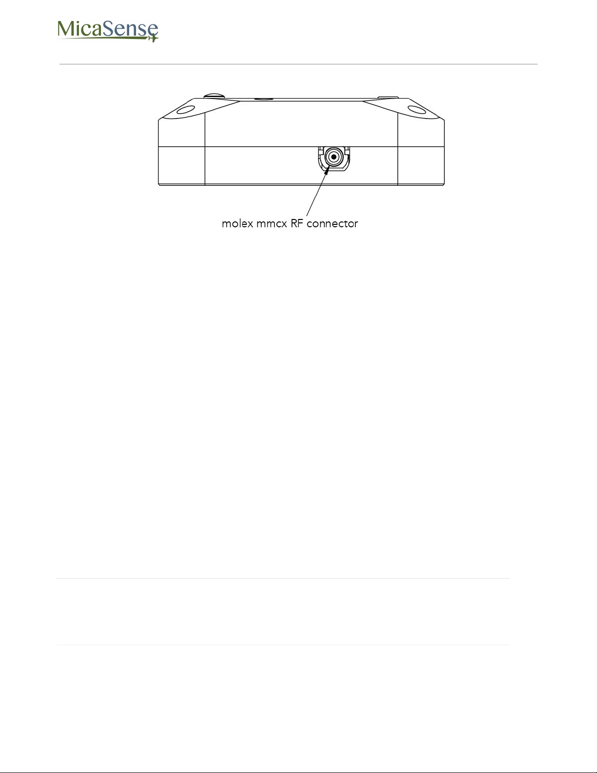
SIDE
DLS 2 Connectors and Buttons
The sensor kit includes all required interface cables to connect to the DLS 2.
The LED camera status indicator mimics the LED signals on the MicaSense sensor. The signal
types are outlined in the Sensor Firmware Guide. The camera trigger button will command a
capture on the MicaSense sensor. This is useful for capturing a preflight image of the
calibration panel.
© 2020 MicaSense, Inc. Page 5 of 17
DLS 2 Integration Guide Rev 03
The RF connector is not available for use at this time but may be used as in the future. When
it is available, we will update this guide.
DLS 2 Installation Guidelines
The DLS 2 should always be the highest object on the aircraft in order to avoid shadows or
reflections. It contains an integral GPS sensor that may be utilized for geotagging of the
MicaSense sensor imagery if system GPS signals are not provided to the sensor by other
means. Install the module where it will have a clear view of the sky, far away from any
devices that could interfere with it (like a data link or video transmitters).
When the DLS 2 starts up, it attempts to calibrate, which requires it to be still and
motionless. Ensure that there is no vibration or movement until the DLS 2 has completed
this procedure, indicated by normal LED status lights (shown in the Firmware Guide).
NOTE
The 6-pin connector on the DLS 2 should be facing forward in the flight direction.
Mounting it in the opposite direction will cause the magnetometer calibration
process to be backwards.
© 2020 MicaSense, Inc. Page 6 of 17

DLS 2 Integration Guide Rev 03
Fixed-wing
Always install the DLS 2 at the high-point of the fuselage (if possible) to avoid any
shadowing or reflections from aircraft fuselage or rotors.
Do not recess or embed the DLS 2 sensor body below the metallic base.
Local reflections could impact light sensor measurements. Avoid bright or metallic paint near
the DLS 2 light sensor as this may interfere with incoming light values.
Multirotor
Install the DLS 2 on a rigid post such that it is the highest object on the aircraft, with a
minimum of 5 cm above the rotor plane.
Ensure that there are no obstructions in the DLS 2’s field of view to the sky, including
propellers and other items on the aircraft.
Keep the DLS 2 away from the aircraft GPS. Installing the DLS 2 near the aircraft GPS may
impact the aircraft’s GPS reception.
DLS 2 Firmware Upgrade
MicaSense Sensor firmware upgrades will periodically contain DLS 2 firmware updates as
well.
To update the firmware on your DLS 2, you can either have it plugged into the camera at the
time you are upgrading the camera’s firmware, or plug the DLS 2 in later after you have
upgraded the camera’s firmware and are ready to use the DLS 2. Remember to not connect
the DLS 2 to the camera with the camera powered ON.
The camera will automatically update the firmware on the DLS 2 if it contains a newer
version.
Magnetometer Calibration
This procedure is for the included GPS only and is not required for configurations that
provide GPS and attitude information via the serial or Ethernet connection. If the
© 2020 MicaSense, Inc. Page 7 of 17
DLS 2 Integration Guide Rev 03
configuration for your sensor is one that uses the provided module for GPS and
magnetometer data, a calibration process for the magnetometer is needed.
NOTE
You will need a compass to verify the calibration once completed.
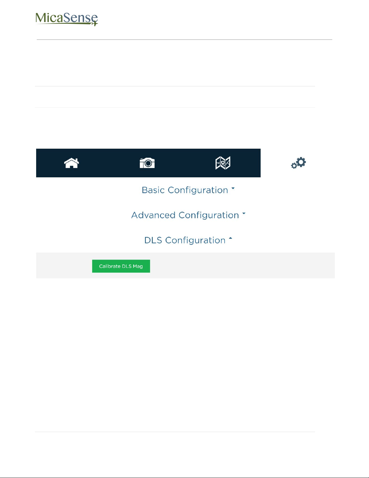
From the Settings page, access the DLS Configuration section.
“Calibrate DLS Mag” is a clickable button that will start the calibration process. This
calibration process is for the magnetometer sensor that is inside the DLS 2 module.
Ensure that the DLS 2 is connected to the Sensor using the provided cables. Additionally,
your DLS 2 module should be rigidly mounted to your aircraft frame.
© 2020 MicaSense, Inc. Page 8 of 17
DLS 2 Integration Guide Rev 03
NOTE
Before beginning the calibration routine, position yourself and the drone away
from large metal objects such as cars and buildings. Also avoid paved areas, which
may have metal rods inside the cement. An open field is preferred to avoid
interaction with any sources of magnetic interference or objects that may perturb
the Earth’s natural magnetic field.
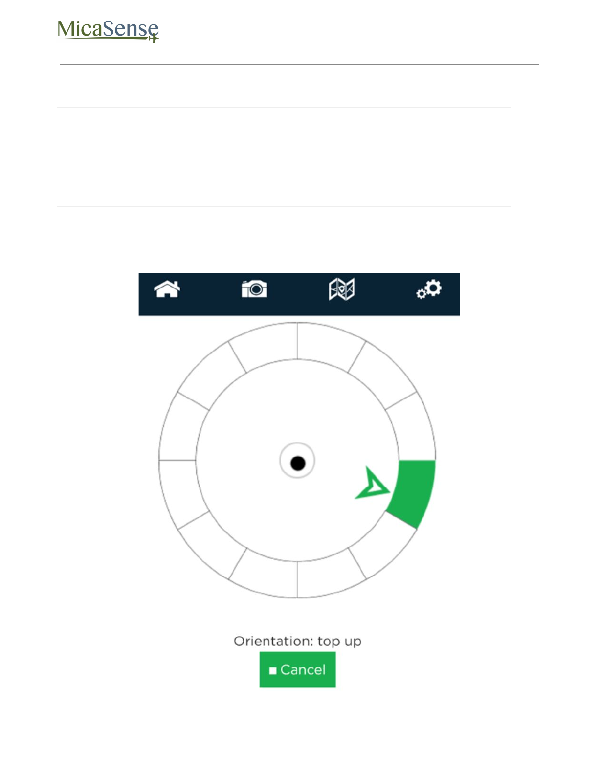
Once the startup sequence has finished, you will be guided through the orientations your
drone should be in for each of the calibration steps.
© 2020 MicaSense, Inc. Page 9 of 17
DLS 2 Integration Guide Rev 03
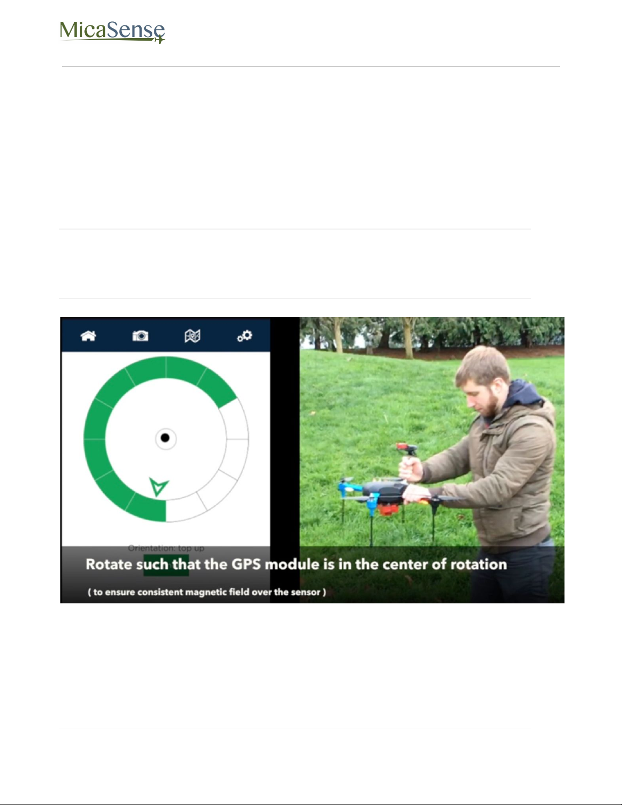
To calibrate the magnetometer, a 6-axis calibration routine needs to be performed. During
the routine, the drone (specifically the DLS 2 module) should remain in a fixed position while
being rotated, i.e. the user performing the calibration should be moving around the
magnetometer. The drone and DLS 2 module should also be kept level to the plane they are
on in each position. The on-screen rotation guide will show you when you have successfully
completed one orientation and can move on to the next.
NOTE
The black dot is a level (like a bubble level), indicating how level the unit is
compared to the plane it is on. It does not indicate how far away from the center of
rotation the unit is.
© 2020 MicaSense, Inc. Page 10 of 17

DLS 2 Integration Guide Rev 03
NOTE
If you are using a Serial or HTTP connection to supply GPS and attitude information
to the sensor, you do not need to perform the magnetometer calibration described
above.
Magnetic Heading Check
Once the calibration routine has been completed, it is important to verify that the
magnetometer information displayed in the Heading section of the sensor’s Home Page is
accurate.
A handheld compass has been provided with your kit that will allow you to verify this in the
field. Access the sensor’s Home Page and use the “Heading” field to check the four cardinal
directions (North, East, South, West) and ensure a good match between the compass and
the reading by the sensor. You should see an error of less than +/- 5 degrees. If this error is
exceeded, redo the magnetometer calibration.
© 2020 MicaSense, Inc. Page 11 of 17

DLS 2 Integration Guide Rev 03
Additionally, you will want to perform a magnetic interference test to verify that your drone
will not affect the heading readings during flight.
© 2020 MicaSense, Inc. Page 12 of 17

DLS 2 Integration Guide Rev 03
Magnetic Interference Check
A test procedure should be conducted any time electrical equipment is added or removed
from the drone to ensure the magnetic field profile of the aircraft has not changed.
To test for any magnetic interference from the drone that is affecting the magnetometer,
start by placing your drone facing North (you can use the magnetic heading from the Wi-Fi
page to align yourself).
⚠ WARNING
The next section involves spinning up the motors of your drone.
If you have a fixed wing aircraft this will require holding the aircraft in place while keeping
clear of the propeller.
If using a multi-rotor, setup the aircraft as if it was ready for a normal take off, but you do not
need to actually take off, just spin up of motors.
You DO NOT need to provide full power to the motor(s).
Throttle up the motor(s) on your drone and ensure that the heading reading has not
changed, then throttle back down. Repeat this for each direction (North, East, South, West)
to ensure there is no magnetic interference in any of the four cardinal directions.
⚠ WARNING
FAILURE TO FOLLOW INSTRUCTIONS TO KEEP CLEAR OF SPINNING BLADES
COULD RESULT IN INJURY OR DEATH.
NOTE
Electromagnetic interference during the operation of your drone can cause errors
in the magnetic heading readings. This can cause the irradiance data generated by
the DLS 2 to be not usable during processing.
© 2020 MicaSense, Inc. Page 13 of 17

DLS 2 Integration Guide Rev 03
Basic Integrations
MicaSense sensors are designed for integration into a variety of platforms. Below are some
common integration configurations.
1. Standalone Integration Using RedEdge-MX and DLS 2
The standalone integration option requires only that power is provided to the RedEdge-MX
system. Triggering is configured via the WiFi interface to either “Overlap” or “Timer” mode.
GPS information is provided by the integrated GPS receiver within the DLS 2.
© 2020 MicaSense, Inc. Page 14 of 17

DLS 2 Integration Guide Rev 03
Example RedEdge-MX + DLS 2 Integration
© 2020 MicaSense, Inc. Page 15 of 17

DLS 2 Integration Guide Rev 03
2. Standalone Integration Using Altum and DLS 2
The standalone integration option requires only that power is provided to the Altum system.
Triggering is configured via the WiFi interface to either “Overlap” or “Timer” mode. GPS
information is provided by the integrated GPS receiver within the DLS 2.
© 2020 MicaSense, Inc. Page 16 of 17

DLS 2 Integration Guide Rev 03
Example Altum + DLS 2 Integration
MicaSense Downwelling Light Sensor 2
Integration Guide
Rev 03 – Jan 2020
MicaSense, Inc.
Seattle WA 98103
●The contents of this guide are subject to change without notice
●MicaSense, Inc. assumes no liability for incidental or consequential damages
arising from the use of this product, and any claims by a third party.
●Copying of the contents of this guide, in whole or in part is prohibited under
the copyright law.
© 2020 MicaSense, Inc. Page 17 of 17
Table of contents
Other MicaSense Accessories manuals


Popular Accessories manuals by other brands


Bin Master
Bin Master NCR-21 operating instructions

MD SPORTS
MD SPORTS Menards BBG015_018M Assembly instructions

Silvercrest
Silvercrest RCS AAA3680-A IP20 Operation and safety notes

A-EON
A-EON Aeotec MultiSensor 6 user guide

ABQINDUSTRIAL
ABQINDUSTRIAL Plug&Test MR01-50 user guide

IB Connect
IB Connect PRISMA user manual


