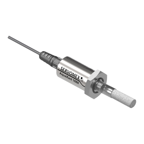
Michell Instruments SF52 User manual

SF52
Dew-Point Transmitter
User’s Manual
97224 Issue 5
June 2017

Please fill out the form(s) below for each instrument that has been purchased.
Use this information when contacting Michell Instruments for service purposes.
Transmitter
Code
Serial Number
Invoice Date
Location of Instrument
Tag No
Transmitter
Code
Serial Number
Invoice Date
Location of Instrument
Tag No
Transmitter
Code
Serial Number
Invoice Date
Location of Instrument
Tag No

© 2015 Michell Instruments
This document is the property of Michell Instruments Ltd. and may not be copied or
otherwise reproduced, communicated in any way to third parties, nor stored in any Data
Processing System without the express written authorization of Michell Instruments Ltd.
SF52 Transmitter
For Michell Instruments' contact information please go to
www.michell.com

SF52 User’s Manual
iv 97224 Issue 5, June 2017
1 INTRODUCTION................................................................................................1
1.1 Features ............................................................................................................ 1
2 INSTALLATION ..................................................................................................2
2.1 Unpacking the Instrument................................................................................... 2
2.2 Electrical Schematic............................................................................................ 3
2.2.1 Electrical Boundaries mA 3-Wire..................................................................... 3
2.3 Transmitter Mounting.......................................................................................... 4
2.3.1 Transmitter Mounting - Sample Block (Optional).............................................. 5
2.3.2 Transmitter Mounting - Direct Pipeline Connection........................................... 6
3 OPERATION ......................................................................................................7
4 MAINTENANCE..................................................................................................8
Contents
Safety ................................................................................................................................ v
Electrical Safety ........................................................................................................... v
Pressure Safety............................................................................................................ v
Toxic Materials............................................................................................................. v
Repair and Maintenance............................................................................................... v
Calibration................................................................................................................... v
Safety Conformity ........................................................................................................ v
Abbreviations......................................................................................................................vi
Warnings............................................................................................................................vi
Appendices
Appendix A Technical Specifications..............................................................................10
A.1 Dimensions.................................................................................11
Appendix B Quality, Recycling & Warranty Information...................................................13
Appendix C Recommended Practices in Humidity Measurements.....................................15
Appendix D Return Document & Decontamination Declaration........................................20
Figures
Figure 1 SF52..........................................................................................................2
Figure 2 Voltage 3-Wire Connections.........................................................................3
Figure 3 mA 3-Wire Connections...............................................................................3
Figure 4 Maximum Load of SF52 3-Wire mA - Including Cable Resistance....................3
Figure 5 Transmitter Mounting..................................................................................5
Figure 6 Transmitter Mounting - Pipe or Duct.............................................................6
Figure 7 Installation Location ...................................................................................7
Figure 8 Indication of Dead Space............................................................................7
Figure 9 Dimensions - SF52....................................................................................11
Figure 10 Dimensions - G½" BSP Sample Block.........................................................11
Figure 11 Dimensions - G½" BSP Sample Block with Filter .........................................11

SF52 User’s Manual
Michell Instruments v
Safety
The manufacturer has designed this equipment to be safe when operated using the procedures
detailed in this manual. The user must not use this equipment for any other purpose than that
stated. Do not apply values greater than the maximum value stated.
This manual contains operating and safety instructions, which must be followed to ensure the safe
operation and to maintain the equipment in a safe condition. The safety instructions are either
warnings or cautions issued to protect the user and the equipment from injury or damage. Use
qualified personnel and good engineering practice for all procedures in this manual.
Electrical Safety
The instrument is designed to be completely safe when used with options and accessories supplied
by the manufacturer for use with the instrument.
Pressure Safety
DO NOT permit pressures greater than the safe working pressure to be applied to the instrument.
The specified safe working pressure is up to 2 MPa, (20 barg / 290 psig)) maximum.
Toxic Materials
The use of hazardous materials in the construction of this instrument has been minimized. During
normal operation it is not possible for the user to come into contact with any hazardous substance
which might be employed in the construction of the instrument. Care should, however, be exercised
during maintenance and the disposal of certain parts.
Repair and Maintenance
The instrument must be maintained either by the manufacturer or an accredited service agent. Refer
to www.michell.com for details of Michell Instruments’ worldwide offices contact information.
Calibration
The recommended calibration interval for this instrument is 12 months. The instrument should be
returned to the manufacturer, Michell Instruments Benelux BV, for re-calibration.
Safety Conformity
This product meets the essential protection requirements of the relevant EU directives. Further
details of applied standards may be found in the product specification.

SF52 User’s Manual
vi 97224 Issue 5, June 2017
Abbreviations
The following abbreviations are used in this manual:
bar pressure unit (=100 kP or 0.987 atm)
°C degrees Celsius
°F degrees Fahrenheit
DC direct current
Dp Dew point
g grams
g/m3grams per cubic meter
gr/ft3grains per cubic foot
m meter(s)
mA milliampere
mm millimetres
psi pounds per square inch
% percentage
oz ounces
RH relative humidity
V Volts
“ inches
‘ feet
Warnings
The following general warning listed below is applicable to this instrument. It is repeated
in the text in the appropriate locations.
Where this hazard warning symbol appears in the following
sections it is used to indicate areas where potentially hazardous
operations need to be carried out.

SF52 User’s Manual
Michell Instruments 1
INTRODUCTION
1 INTRODUCTION
The SF52 dew-point transmitter is a simple, cost effective sensor designed for use in
harsh industrial dryer applications where reliability and toughness are required at an
economical cost.
The SF52 is available with a choice of G ½” and ½” NPT process connections and
voltage or mA outputs. A key feature of the unit is the recessed and protected measuring
element giving an extended sensor life cycle.
Michell's polymer based sensor is calibrated on a high volume traceable calibration
system, providing OEM quantities of units on short deliveries, each with a 3 point
calibration certificate.
1.1 Features
• Ideal for OEM dryer use
• Dew-point measurement range -40 to +60°C (-40 to +140°F)
• Fast response
• Rugged IP65 construction
• 3-point traceable calibration certificate
• Accuracy ±2°C
• Voltage or mA outputs
The SF52 is available with a voltage output (0 to 1 V, 0 to 5 V, 0 to 10 V) or
a current output (4 - 20 mA 3 wire).
The current output has a 3 point diagnostic option:
Sensor fault 23 mA
Under-range dew point 4 mA
Over-range dew point 20 mA
These three values are standard factory programmed and are normally switched off.
Other diagnostic settings are available, please contact Michell Instruments for further
information.

SF52 User’s Manual
297224 Issue 5, June 2017
INSTALLATION
2 INSTALLATION
2.1 Unpacking the Instrument
On delivery, check that all the following standard components are in the packing box:
• SF52 transmitter
• G ½” BSP - Bonded seal fitted over threaded part of transmitter body.
NOTE: Not applicable to the ½" NPT
• Certificate of calibration
• Quick Start Guide
NOTE: If any component is not present, contact Michell Instruments
immediately.
NOTE: Do not touch the filter disc at the front of the SF52.
Figure 1
SF52

SF52 User’s Manual
Michell Instruments 3
INSTALLATION
2.2 Electrical Schematic
White
Green
Yellow (do not use)
Brown
Supply
14 to 30 V for 0 to 10 V output
8 to 30 V for 0 to 1 V output
Figure 2
Voltage 3-Wire Connections
Supply
8 to 30 V for 4 - 20 mA output
White
Green Max load
20 mA
Yellow (do not use)
Brown
Figure 3
mA 3-Wire Connections
2.2.1 Electrical Boundaries mA 3-Wire
100
0
0 5 10 15 20 25 30
200
300
400
500
600
700
800
900
1000
Resistance (ohm)
Figure 4
Maximum Load of SF52 3-Wire mA - Including Cable Resistance

SF52 User’s Manual
497224 Issue 5, June 2017
INSTALLATION
2.3 Transmitter Mounting
Take care to prevent any contamination of the sensor before installation (handle the
transmitter by the main body only, avoiding contact with the filter disc).
The SF52 can be mounted either into a flow-through sensor sampling block (optional)
or directly into a pipe or duct. It can be operated at pressures of up to 2 MPa (20 barg
/ 290 psig) when fitted with the bonded seal provided.
The recommended gas flow rate, when mounted in the optional sampling block, is 1 to
5 Nl/min (2.1 to 10.6 scfh). However, for direct insertion applications, gas flow can be
from static to 10 m/sec (32.8 fps).
NOTE: Pass the seal over the mounting thread and assemble into the sampling
location, by hand, using the wrench flats only.
When installed, fully tighten using a wrench until the seal is fully compressed and to the
following torque settings:
• G ½” BSP 56 Nm (41.3 ft-lbs)
• ½” NPT 56 Nm (41.3 ft-lbs)

SF52 User’s Manual
Michell Instruments 5
INSTALLATION
2.3.1 Transmitter Mounting - Sample Block (Optional)
(Applicable to the SF52 G ½ - BSP version ONLY)
The following procedure must be carried out by a qualified
installation engineer.
To mount the transmitter into the sensor block (preferred method), proceed as follows,
refer to
Figure 5.
1. Fit the bonded seal (2) over the threaded part of the transmitter body.
NOTE: The bonded seal has a flat side and a rounded side. It is
important that the flat side is next to the sensor steel body in
order to give it the correct seal.
Under no circumstances should the filter disc be handled with
the fingers.
2. Screw the transmitter (1) into the sample block (3) and tighten to the
appropriate torque setting (see Section 2.3). NOTE: Use the flats of
the hexagonal body tube and not the sensor body.
3. Connect the SF52 TPE cable wiring connections into the electrical system.
3
2
1
Figure 5
Transmitter Mounting

SF52 User’s Manual
697224 Issue 5, June 2017
INSTALLATION
2.3.2 Transmitter Mounting - Direct Pipeline Connection
The transmitter may be directly mounted into a pipe or duct as shown in
Figure 6.
Caution: Do not mount the transmitter too close to the bottom
of a bend where any condensate in the pipeline might collect
and saturate the probe.
The pipe or duct will require a thread to match the transmitter body thread. Fixing
dimensions are shown in
Figure 6.
For circular pipework, to ensure the integrity of a
gas tight seal, a mounting flange will be required on the pipework in order to provide a
flat surface to seal against.
The following procedure must be carried out by competent
personnel.
WARNING: Under no circumstances should the filter disc be
handled with the fingers.
1. G ½” ONLY - Ensure that the bonded seal (2) is over the threaded part
of the transmitter body.
2. Screw the transmitter (3) into the pipe (1). Tighten enough to obtain
a gas tight seal. NOTE: Do not overtighten or the thread on the
pipework may be stripped.
1
1
2
2
3
3
Optional
display
(available
on request)
Cable
j
j
Figure 6
Transmitter Mounting - Pipe or Duct

SF52 User’s Manual
Michell Instruments 7
OPERATION
3 OPERATION
Operation is very simple, assuming the following installation techniques are adhered to:
Sampling Hints
Be Sure the Sample is Representative of the Gas Under Test:
The sample point should be as close to the critical measurement point as possible. Also,
never sample from the bottom of a pipe as entrained liquids may be drawn into the
sensing element.
2
3
Figure 7
Installation Location
Minimize Dead Space in Sample Lines:
Dead space causes moisture entrapment points, increased system response times and
measurement errors, as a result of the trapped moisture being released into the passing
sample gas and causing an increase in partial vapor pressure.
Deadspace
Figure 8
Indication of Dead Space
Remove Any Particulate Matter or Oil from the Gas Sample:
Particulate matter may ‘blind’ the sensing element and reduce its response speed. If
particulate, such as degraded desiccant, pipe scale or rust is present in the sample gas,
use an in-line filter, as a minimum level of protection. For more demanding applications
Michell Instruments offers a range of sampling systems (for more information contact
www.michell.com).
Use High Quality Sample Tube and Fittings:
Michell Instruments recommends that, wherever possible, stainless steel tubing and
fittings should be used. This is particularly important at low dew points since other
materials have hygroscopic characteristics and adsorb moisture on the tube walls,
slowing down response and, in extreme circumstances, giving false readings. For
temporary applications, or where stainless steel tubing is not practical, use high quality
thick walled PTFE tubing.
Position Transmitter away from Heat Source:
It is recommended, as good instrumentation practice, that the transmitter is placed
away from any heat source to avoid adsorption/desorption.

SF52 User’s Manual
897224 Issue 5, June 2017
MAINTENANCE
4 MAINTENANCE
Calibration
Routine maintenance of the SF52 is confined to regular re-calibration by exposure of
the transmitter to sample gases of known moisture content to ensure that the stated
accuracy is maintained. Calibration services traceable to the UK
National Physical
Laboratory
(NPL) and the US
National Institute of Standards and Technology
(NIST) are
provided by Michell Instruments.
Michell Instruments offers a variety of re-calibration schemes to suit specific needs. A
Michell representative can provide detailed, custom advice (refer to www.michell.com for
details of Michell Instruments’ worldwide offices contact information).
Bonded Seal
If the installed bonded seal gets damaged or lost, replacement bonded seals G½-BSP
(order code A000340) can be obtained by contacting Michell Instruments, or your local
distributor.

SF52 User’s Manual
Michell Instruments 9
APPENDIX A
Appendix A
Technical Specifications

SF52 User’s Manual
10 97224 Issue 5, June 2017
APPENDIX A
Appendix A Technical Specifications
Performance
Measurement Range -40 to +60°Cdp (-40 to +140°Fdp)
Accuracy ±2°Cdp (±3.6°Fdp)
Repeatability 0.5°Cdp (0.9°Fdp)
Stability <1°C / year (<1.8°F / year)
Accuracy (absolute humidity) 0.4 to 3 g/m3on value of absolute humidity
Calibration Traceable 3-point calibration certificate
Electrical Specifications
Output Signal 0 to 1, 0 to 5, 0 to 10 V or 4-20 mA (3-wire)
Output Dew point, absolute humidity
Analog Output Scaled Range
Standard -40 to +60°C (-40 to +140°F)
-30 to +30°C (-22 to +86°F)
0 to 200 g/m3
Non-standard available upon request
Supply Voltage 14 to 30 V DC (for 0 to 10 V output)
8 to 30 V DC (for 0 to 1 / 0 to 5 V / 4-20 mA output)
Current Consumption V output <9 mA
mA output <29 mA
CE Marked Certified
Operating Specifications
Operating Humidity 0 - 100% RH
Operating Temperature -40 to +60°C (-40 to +140°F)
Operating Pressure 2 MPa (20 barg / 290 psig) maximum
Thermal Compensation Characterized across operating temperature range
Mechanical Specifications
Ingress Protection IP66 in accordance with standard BS EN 60529:1992
NEMA 4 in accordance with standard NEMA 250-2003
Housing Material Nickel-coated brass
Dimensions L=85mm, ø 24mm (L=3.34”, ø 0.94”) (max)
Filter HDPE front filter
Process Connection G ½" BSP, ½" NPT
Weight 320g (11.29oz)
Cable 2m (6.6’) halogen free TPE cable
Diagnostic Settings
(factory programmed)
Condition
Sensor fault
Under-range dew point
Over-range dew point
Output
23 mA
4 mA
20 mA

SF52 User’s Manual
Michell Instruments 11
APPENDIX A
A.1 Dimensions
G1/2” BSP bonded seal
Ø28.65 x 2.61mm
(Ø1.12 x 0.10”)
Figure 9
Dimensions - SF52
SECTION ON A-A
35.0H11
O
26.8
O
12
O
14.3
3
70
39
40
O
45
49
15.0 2.2
19.5
19.0
O
28
3
M24 x 1.5-7H
(LOOSE FIT)
2 OFF
TAP M6 x 5 FTD
1 x 45
v
BOTH ENDS
TAP 1/8" BSP
TAP 1/4" BSP
3.2
3.2
3.2
3.2
A
A
TAP 1/2" BSP x 18.0 DEEP
MINIMAL CHAMFER LEAD-IN
TO REMOVE SHARP EDGES
100
28
O
40 20.0
30
19 20
Figure 10
Dimensions - G½" BSP Sample Block
Ø 39mm
(Ø 1.5”)
19mm
(0.75”)
20mm
(0.79”)
20mm
(0.79”)
100mm
(3.9”)
40mm
(1.6”)
30mm
(1.2”) Ø28mm
(Ø1.1”)
TAP 1/4” BSP
Figure 11
Dimensions - G½" BSP Sample Block with Filter

SF52 User’s Manual
12 97224 Issue 5, June 2017
APPENDIX B
Appendix B
Quality, Recycling
& Warranty
Information

SF52 User’s Manual
Michell Instruments 13
APPENDIX B
Appendix B Quality, Recycling & Warranty Information
Michell Instruments is dedicated to complying to all relevant legislation and directives. Full information
can be found on our website at:
www.michell.com/compliance
This page contains information on the following directives:
• ATEX Directive
• Calibration Facilities
• Conflict Minerals
• FCC Statement
• Manufacturing Quality
• Modern Slavery Statement
• Pressure Equipment Directive
• REACH
• RoHS2
• WEEE2
• Recycling Policy
• Warranty and Returns
This information is also available in PDF format.

SF52 User’s Manual
14 97224 Issue 5, June 2017
APPENDIX C
Appendix C
Recommended Practices in
Humidity Measurement
Table of contents
Other Michell Instruments Transmitter manuals
Michell Instruments
Michell Instruments DT722 User manual
Michell Instruments
Michell Instruments Easidew PRO I.S. User manual
Michell Instruments
Michell Instruments Easidew User manual

Michell Instruments
Michell Instruments Easidew PRO XP User manual
Michell Instruments
Michell Instruments Easidew I.S. User manual

Michell Instruments
Michell Instruments SF82 Series User manual
Michell Instruments
Michell Instruments Pura 2-Wire User manual

Michell Instruments
Michell Instruments Easidew User manual
Michell Instruments
Michell Instruments SF72 User manual
