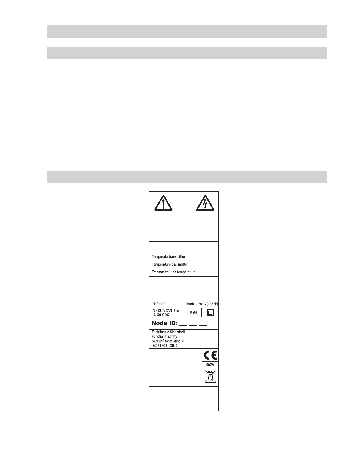
GESTRA TRV 5-40 User manual

1
EN
English
Temperature Transmitter
TRV 5-40
Original Installation Instructions
818712-01

2
Contents
Usage for the intended purpose ..............................................................................................................4
Safety note .............................................................................................................................................4
PED (Pressure Equipment Directive) .......................................................................................................4
ATEX (Atmosphère Explosible) ................................................................................................................4
Note on the Declaration of Conformity / Declaration by the Manufacturer ..........................................4
Important Notes
Page
Explanatory Notes
Scope of supply......................................................................................................................................4
Description ......................................................................................................................................... 4, 5
Function .................................................................................................................................................5
System components ...............................................................................................................................5
Basic Settings
Factory settings ....................................................................................................................................14
TRV 5-40..........................................................................................................................................6 – 7
Name plate / Marking .............................................................................................................................7
Dimensions TRV 5-40 .............................................................................................................................8
Technical Data
Temperature transmitter TRV 5-40..........................................................................................................9
Note .......................................................................................................................................................9
Check and if necessary change settings .................................................................................................9
Tools ......................................................................................................................................................9
Installation
Wiring
Wiring of the temperature sensor..........................................................................................................11
Bus line, cable length and size..............................................................................................................11
Wiring diagram for temperature transmitter TRV 5-40 .................................................................... 12, 13
Connecting the connector and jack.......................................................................................................13
Tools ....................................................................................................................................................13
TRV 5-40..............................................................................................................................................10
Key.......................................................................................................................................................10
Functional Elements

3
TRV 5-40..............................................................................................................................................17
Start, Operation and Test
Checking wiring....................................................................................................................................14
Applying supply voltage ........................................................................................................................14
Changing system configuration....................................................................................................... 14, 15
Examples of configuration settings .......................................................................................................15
Adjusting temp. limit TMAX (°C) ..............................................................................................................16
Contents – continued –
Commissioning
CAN bus ...............................................................................................................................................23
Factory settings of node ID ...................................................................................................................23
Node ID ................................................................................................................................................24
Changing node ID for safety part ..........................................................................................................24
Table “Node ID”....................................................................................................................................25
Table Baud rate ....................................................................................................................................25
Decommissioning .................................................................................................................................26
Disposal ...............................................................................................................................................26
Annex
Causes .................................................................................................................................................18
Note .....................................................................................................................................................18
Systematic malfunction analysis ..........................................................................................................19
Table listing error codes .......................................................................................................................20
Note .....................................................................................................................................................21
Basic values of measuring resistors......................................................................................................21
System Malfunctions
Fault-finding list for TRV 5-40 / NRS 1-40.1 / NRS 1-40.2.....................................................................22
Malfunctions
Page
Checking the switchpoints....................................................................................................................21
Checking Installation and Functions

4
Important Notes
Usage for the intended purpose
The temperature transmitter TRV 5-40 in conjunction with the temperature sensors TRG 5-63,
TRG 5-64, TRG 5-65, TRAG 5-67 and TRG 5-58 must only be used for measuring temperatures.
Safety note
The equipment must only be installed and commissioned by qualified and competent staff.
Retrofitting and maintenance work must only be performed by qualified personnel who – through
adequate training – have achieved a recognised level of competence.
PED (Pressure Equipment Directive)
ATEX (Atmosphère Explosible)
According to the European Directive 2014/34/EU the equipment must not be used in explosion risk
areas.
The equipment fulfils the requirements of the Pressure Equipment Directive 2014/68/EU and can be
used with fluids of group 1 and 2. With CE marking.
Explanatory Notes
Scope of supply
TRV 5-40
1 Temperature transmitter TRV 5-40
4 Fixing lugs
1 M 12 sensor connector, 5 poles, A-coded, with terminating resistor 120 Ω
1 Installation manual
Description
The temperature transmitter TRV 5-40 is designed for the connection of three temperature sensors
TRG 5-6x (platinum resistance thermometer Pt 100 to EN 60751). The temperatures measured by the
temperature sensors are converted by the temperature transmitter TRV 5-40 and sent to the CAN bus
in the form of a data telegram.
The data are transferred via CAN bus, using the CANopen protocol.
For details on the conformity of our equipment according to the European Directives see our Declaration
of Conformity or our Declaration of Manufacturer.
The current Declaration of Conformity and Declaration of Manufacturer are available in the Internet under
www.gestra.com documents
or can be requested from us.
Note on the Declaration of Conformity / Declaration by the Manufacturer

5
Explanatory Notes – continued –
Description – continued –
The temperature transmitter TRV 5-40 can be used as:
nsafety temperature monitor / limiter in conjunction with a temperature sensor type TRG 5-6x and
the control unit NRS 1-40.1 / NRS 1-40.2 and
ntemperature monitor & limiter in conjunction with one or two temperature sensors TRG 5-6x and the
control unit TRS 5-40 or any other equipment that is approved for this application.
The equipment combination can be used for monitoring, limiting or control purposes in steam plants
and (pressurised) hot water installations according to TRD and EN 12952 and EN 12953.
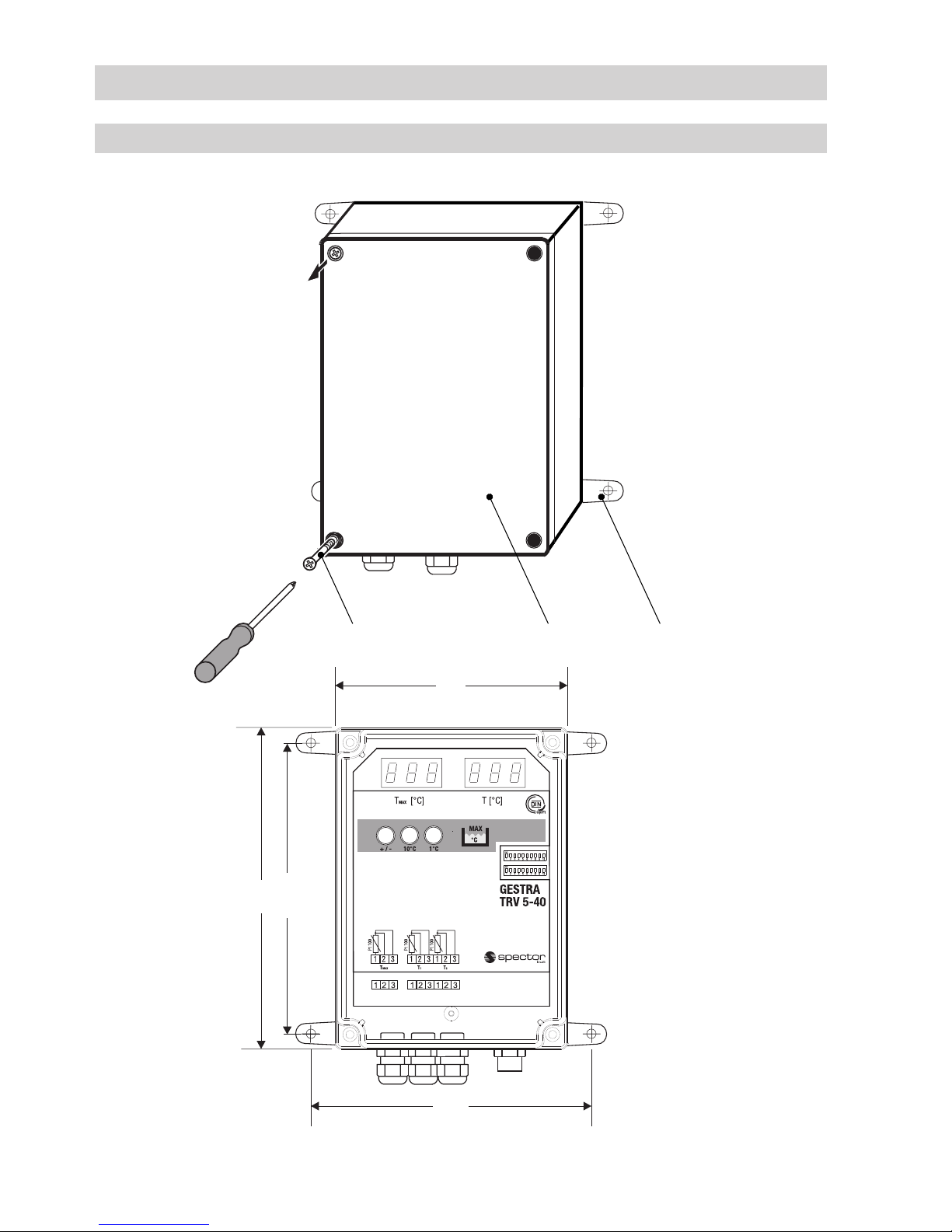
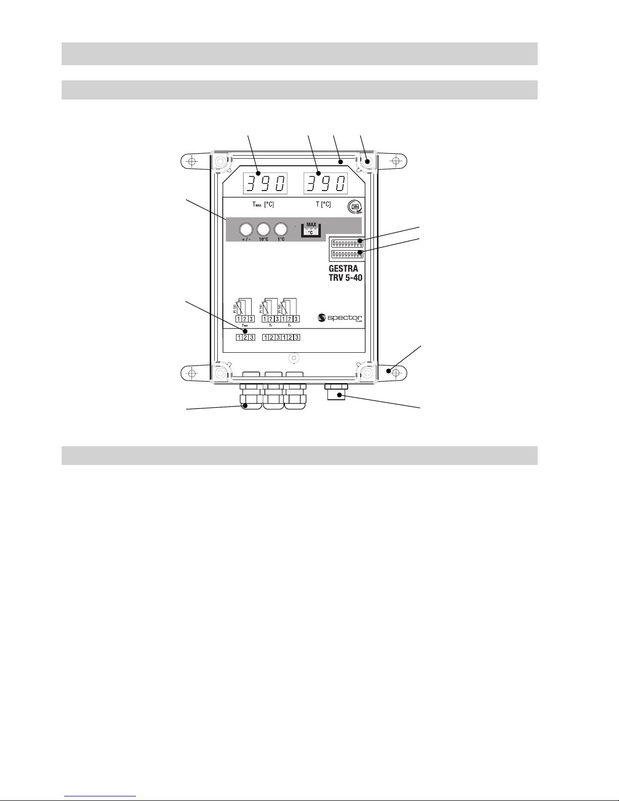
Function
The temperature transmitter TRV 5-40 consists of the safety part for temperature limiting and the part
for temperature monitoring & control.
The safety part is connected with the temperature sensor. The temperature sensor detects the tem-
perature and sends the measured values to the safety part of the temperature transmitter, where the
measured values are recorded redundantly and monitored.
The adjustable temperature limit TMAX (°C), the actual temperature and system malfunctions are
indicated by the temperature transmitter. The temperature sensing element on the electronic insert
monitors continuously the temperature inside the transmitter housing. An automatic self-testing routine
checks every 10 seconds the safety and reliability of the functions of the temperature sensor and the
detection of the measured values.
The actual temperatures, the exceeding of the adjusted temperature limit TMAX (°C), the result of the
periodic self test and the temperature inside the transmitter housing are sent as a data telegram via
CAN bus to the control equipment NRS 1-40.1 / NRS 1-40.2.
Regardless of the safety part two additional temperature sensors TRG 5-6x can be used for tempera-
ture monitoring & control in order to measure further actual temperature values. These readings are
also sent as data telegrams via CAN bus and will be evaluated e. g. by the control unit TRS 5-40.
System components
TRG 5-6x
Temperature sensor with resistance thermometer Pt 100
TRS 5-40
Digital temperature switch
Functions: MIN / MAX temperature monitor and temperature controller
Data exchange: CAN bus to ISO 11898 via CANopen protocol
NRS 1-40.1 and NRS 1-40.2
Digital control unit for four sensors (level, temperature)
Functions: Signalling MIN alarm and MAX alarm in freely adjustable combinations
Data exchange: CAN bus to ISO 11898 via CANopen protocol
URB 2
Operating & visual display unit
Functions: Parameterisation, visual indication via LCD display
Data exchange: CAN bus to ISO 11898, with CANopen protocol

6
TRV 5-40
Type approval
TÜV. SWB/SHWS. 03–413
EG BAF-MUC 03 07 103881 004
DIN registry no. STW (STB) 117 906
Input/Output
CAN bus interface with current supply 18 – 36 V DC, short circuit protected
Temperature sensors
TRG 5-63
1x Pt 100 to EN 60751
TRG 5-64
2x Pt 100 to EN 60751
TRG 5-65, TRG 5-66
1x Pt 100 to EN 60751
TRG 5-67
1x Pt 100 to EN 60751
TRG 5-68
2x Pt 100 to EN 60751
Temperature limit TMAX (°C) (cut-off temperature)
Min. adjustable limit value: 20°C
Max. adjustable limit value: 650°C
Indicators and adjustors
1 Red three-digit, seven-segment LED display for indicating limit values
1 Green three-digit, seven-segment LED display for indicating the actual value
3 Pushbuttons for limit settings
5 LEDs for internal status messages
1 Code switch with 10 poles for setting the node ID and baud rate
1 Code switch with 10 poles for configuring the system
Internal self-checking routine
Every 10 seconds
Fault response time
30 sec.
Power consumption
2 W
Fuse
Electronic thermal fuse TMAX 85°C, hysteresis –2K
Protection
IP 65 to EN 60529
Max. admissible ambient temperature
70°C
Technical Data

7
TRV 5-40 – continued –
Housing
Material: polycarbonate
Cable entry / Wiring
For connecting the temperature sensor:
Cable glands with integrated cable clamp, 3 x M 16,
1 three-pole and 1 six-pole screw-type terminal strip, conductor size 1.5 mm2
For CAN bus connection:
M 12 sensor connector, 5 poles, A coded
M 12 sensor jack, 5 poles, A coded
Weight
Approx. 0.7 kg
Technical Data – continued –
Name plate / Marking
Fig. 1
GESTRA AG
Münchener Str. 77
D-28215 Bremen
Betriebsanleitung beachten
See installation instructions
Voir instructions de montage
TRV 5 - 40
T°
C
MAX ........................
DIN STW (STB) 117908
TÜV . SWB/SHWS
STW(STB) . XX - 413
A
B
C
D
43 21
Typenschild
TRV 5-40
CorelDraw X3
Examiner
Designer
Drawer
Scale
Refer to protection
notice ISO 16016!
Free size tolerance
ISO 2768 mk 1:1
No Änderung/Modification Datum/Date Geänd/Modif. PrüferKonstr.
Datum/Date Name/Name
Nr./No
Ersatz für/Replaces Ersetzt durch/Replaced by
Ersteller/
Konstrukteur/
Prüfer/
Freimaßtoleranzen
ISO 2768 mk
GESTRA
Schutzvermerk
ISO 16016 beachten!
Maßstab/
Nr./ M-Nr.
--
Laupichler
07 Das Design hat sich geändert. 2012-12-12 Paul Laup. 12468
Paul
4-392181-08
43
135
08 2013-08-16 Paul Laupich. 12587TÜV.SWB/SHWS STW(STB). 08 - 413 in 13 - 413 geändert

8
Dimensions TRV 5-40
Technical Data – continued –
Fig. 2
b = 60
ABC
180
163.5
168
130

9
Installation
Check and if necessary change settings
1. Undo cross recess head screws Aand swing up the housing cover B.
2. Use pushbuttons Kfor setting the temperature limit TMAX (°C).
3. Use code switches Fand Gto set the system parameters.
4. Close the housing cover Band fasten the cross recess head screws A.
Temperature transmitter TRV 5-40
Note
After mounting the housing you must:
nconnect the temperature sensor,
nset the temperature limit TMAX (°C) (see chapter “Commissioning”)
ncheck and if necessary change the baud rate setting (see chapter “Wiring”)
ncheck and if necessary change the system configuration (see chapter
“Commissioning”)
ncheck and if necessary change the node ID (see chapter “Annex”)
The temperature transmitter TRV 5-40 is designed for wall mounting. Screw the four fixing lugs
supplied with the transmitter into the housing. You can now attach the equipment to the wall without
having to open the housing cover.
Tools
nScrewdriver 5.5/100
nScrewdriver for cross recess head screws, size 2

10
TRV 5-40
Functional Elements
ACross recess head screws
BHousing cover
CFixing lugs for wall mounting
DIndication of limit setting
EIndication of actual value
FCode switch for node ID and baud rate setting
GCode switch for system configuration
HM 12 connector/jack, 5 poles, A-coded
ICable gland for temperature sensor
JTerminals for temperature sensor
KPushbuttons for limit setting
Key
Fig. 3
D B
E
C
F
G
A
K
J
IH

11
Wiring
Wiring of the temperature sensor
Note that screened four-core cable, e. g. Ölflex®110CH, Lapp, 4 x 0.5 mm2is required for wiring
the equipment. Max. cable length between temperature sensor and temperature transmitter
TRV 5-40: 25 m.
When the equipment is open:
1. Undo cable gland Iand pull the cables of the sensors through the glands.
2. Strip off approx. 40 mm of cable insulation coating, remove approx. 5 mm of conductor end
insulation and disconnect the screen. Note that the screen must only be connected to the
temperature sensor.
3. Connect the sensor cables according to the wiring diagram to the terminal strip J.
4. Fasten cable glands Ito achieve a good seal. Use sealing plugs to seal off cable glands that are
not used.
Bus line, cable length and size
Note that screened multi-core twisted-pair control cable is required for the BUS line, e. g. UNITRONIC®
BUS CAN 2 x 2 x … mm2or RE-2YCYV-fl 2 x 2 x … mm2.
Preassembled control cables (with connector and coupler) for connecting the equipment are available
as accessories.
The baud rate (data transfer rate) dictates the cable length between the bus nodes and the total power
consumption of the sensor dictates the conductor size.
When the equipment is open you can set the baud rate by using the code switch FFig. 3 (S 8 to 10).
The baud rate of the temperature transmitter TRV 5-40 is set at our works to 250 kBit/s (for a max.
cable length of 125 m). Reduce the baud rate if the cable length exceeds 125 m. Make sure that all
bus nodes feature the same baud rate setting.
S 8 S 9 S 10 Baud rate Cable length Number of pairs
and conductor size [mm2]
OFF ON OFF 250 kBit/s 125 m 2 x 2 x 0.34
Factory setting
ON ON OFF 125 kBit/s 250 m 2 x 2 x 0.5
OFF OFF ON 100 kBit/s 335 m 2 x 2 x 0.75
ON OFF ON 50 kBit/s 500 m on request, dependent on
bus configuration
OFF ON ON 20 kBit/s 1000 m
ON ON ON 10 kBit/s 1000 m
Note
The specified max. baud rates and cable lengths are based on empirical values
ascertained by GESTRA. However for some applications it might be necessary to reduce
the baud rate in order to ensure trouble-free operation.
UNITRONIC®is a registered trademark of LAPP Kabelwerke GmbH, Stuttgart.

12
Wiring – continued –
Wiring diagram for temperature transmitter TRV 5-40
Fig. 4
3 144512 253 Key
1Screen
2Voltage supply
24 V DC+
3Voltage supply
24 V DC–
4CAN data line CH
5CAN data line CL
6Terminating resistor 120 Ω
6
Connection of temp. sensor
used as safety limiter Connection of temp. sensor
used as temperature monitor
Connector Coupler
Coupler with terminating resistor 120 Ω Connector with terminating resistor 120 Ω
Central
earthing point
CEP
Control unit
NRS 1-4x
NRS 2-40
NRR 2-40
LRR 1-40
TRS 5-40
Operating unit
URB 2
Level/
Conductivity
electrode
NRG x6-4x
LRG xx-4x
Temperature
transmitter
TRV 5-40

13
Wiring – continued –
Wiring diagram for temperature transmitter TRV 5-40 – continued –
Attention
nWire equipment in series. Start-type wiring is not permitted!
nLink screens of bus cables such that electrical continuity is ensured and connect them
once to the central earthing point (CEP).
nConnect the screens of the sensor lines only once to the temperature sensor
(EMC cable gland).
nIf two or more system components are connected in a CAN bus the first and the last
item of equipment must be provided with a terminating resistor of 120 Ω (terminals
CH/CL). We recommend that you use the TRV 5-40 equipped with the connector fitted
with the terminating resistor either as first or as last equipment.
nThe CAN bus network must not be interrupted during operation.
In the event of an interruption an alarm message will be triggered.
Connecting the connector and jack
If you do not use the preassembled control cables connect the connector and the jacks for the CAN bus
lines in accordance with the wiring diagram.
Tools
nScrewdriver for slotted screws, size 2.5, completely insulated to VDE 0680-1
nScrewdriver for cross recess head screws, size 2

14
Basic Settings
Factory settings
The temperature transmitter TRV 5-40 features the following factory set default values:
nNode ID: 005 for the safety part
nBaud rate: 250 kBit/s (125 m cable length)
nConfiguration: temperature transmitter TRV 5-40 set as limiter 4.
Commissioning
Checking wiring
Before installation check the wiring:
nAre the temperature sensors wired according to the wiring diagram?
nIs the wiring of all CAN bus devices in accordance with the wiring diagrams?
nIs the polarity of the bus line always correct?
nAre all the end-of-line devices of the bus line provided with a 120 Ω terminating resistor?
Applying supply voltage
Switch on supply voltage. The two seven-segment indicators are tested, which means that all
segments and decimal points are flashing. The test is also carried out whenever the connector for the
bus line is pulled out of the transmitter and then plugged in again.
Changing system configuration
The control units NRS 1-40.1 and NRS 1-40.2 associated with the temperature transmitter TRV 5-40
are designed for four limiting functions for monitoring liquid level and temperature. The level electrodes
NRG 1x-40, NRG 1x-41.1 and the temperature transmitter TRV 5-40 are to be connected to the control
unit NRS 1-40.1. The level electrode NRG 1x-41 and the temperature transmitter TRV 5-40 have to be
connected to the control unit 1-40.2.
For the operation of the limiting system it is necessary to establish in the control unit the number of
sensors with which the equipment has to work.
For more information see chapter “Commissioning” in the installation manual NRS 1-40.1 and
NRS 1-40.2.
The following settings can be adjusted with the TRV 5-40:
nCommunication with control unit NRS 1-40.1 or NRS 1-40.2
nCommunication with the control unit operating as limiter 1, 2, 3 or 4

15
Commissioning – continued –
Examples of configuration settings
1 Example
The following items of equipment are connected to the control unit NRS 1-40.1:
2 Level electrodes NRG 1x-40 for low water level LW 1 and 2
1 Level electrode NRG 1x-41.1 for high water level HW and
1 Temperature transmitter TRV 5-40 for MAX temperature
As only in the temperature transmitter TRV 5-40 the limiter number can be adjusted, the control unit
NRS 1-40.1 has to be configured as follows:
Limiter B1 B2 B3 B4
Function Water level LW 1 Water level LW 2 High water HW Temperature MAX
Set the temperature transmitter TRV 5-40 as limiter 4.
2 Example
The following items of equipment are connected to the control unit NRS 1-40.1:
2 Level electrodes NRG 1x-40 for water level LW 1 and 2 and
1 Temperature transmitter TRV 5-40 for MAX temperature
Limiter B1 B2 B3 B4
Function Water level LW 1 Water level LW 2 Temperature MAX
Set the temperature transmitter TRV 5-40 as limiter 3.
Changing system configuration – continued –
G
Toggle switch white
Code switch GLimiter
Number
S1 S2 S3 S4 S5 S6 S7 S8
ON ON OFF OFF OFF OFF OFF OFF 1
OFF OFF ON ON OFF OFF OFF OFF 2
OFF OFF OFF OFF ON ON OFF OFF 3
OFF OFF OFF OFF OFF OFF ON ON 4
Factory setting
S9 S10 Communication with control unit
OFF OFF NRS 1-40.1
ON ON NRS 1-40.2

16
Commissioning – continued –
Adjusting temp. limit TMAX (°C)
Note
In the parameter setting mode the currently adjusted value is indicated by both seven-
segment LED displays.
When the housing is open:
Setting the temperature limit TMAX (°C)
Use the three pushbuttons to set the temperature limit TMAX (°C).
The pushbuttons have the following functions:
nPushbutton to the right: setting in increments of 1°C
nPushbutton in the middle: setting in increments of 10°C
nPushbutton to the left: +/– (increase/decrease)
Upon application of the supply voltage and during operation, the adjusted temp. limit TMAX (°C) and the
actual value are indicated.
Press any of the three pushbuttons to switch to the parameter setting mode of the TRV 5-40. Both
seven-segment LED displays show the adjusted limit value TMAX (°C) and all digital points are flashing.
The adjusted limit TMAX (°C) remains valid until the setting of the new value is finished.
If no other pushbutton is pressed within 10 seconds the temperature transmitter switches back to
normal operation.
Increasing the limit value
When you are in the parameter setting mode press the right (increments of 1°) and/or middle
(increments of 10°C) pushbutton to adjust the desired new limit TMAX (°C).
To increase or decrease the setting use the left pushbutton (+/–).
Decreasing the limit value
When you are in the parameter setting mode first press the left pushbutton (+/–). Then press the
right (increments of 1°) and/or middle (increments of 10°C) pushbutton to adjust the desired new limit
TMAX (°C).
To increase or decrease the setting use the left pushbutton (+/–).
After you have finished the new setting do not press a pushbutton for 10 seconds. The new limit value
TMAX (°C) is then accepted by the temperature transmitter TRV 5-40 and the equipment switches back
to normal operation. The new limit value TMAX (°C) and the actual value will now be indicated.
Please write the new temperature limit TMAX (°C) on the name plate.
Fig. 5
Indication of
limit value
Pushbuttons for
limit setting
Indication of
actual value / error code

17
Start
Apply supply voltage. All segments and decimal
points of the displays
TMAX and T are flashing.
The LED displays are being tested.
Operation
Actual value T (°C) below limit
value TMAX (°C)
Display TMAX Indication of the adjusted limit
Display T Indication of the actual value
Actual value T (°C) above limit
value TMAX (°C)
Display TMAX Indication of the adjusted limit
Display T Indication of the actual value and triggering of
an alarm.
Control unit NRS 1-40.1 / NRS 1-40.2 opens the
output contacts after the time delay has elapsed.
Test
The pushbutton for the TRV
5-40 on the control unit NRS
1-40.1 / NRS 1-40.2 must be
pressed and held down until
the test is finished.
Display T An increase in temperature is simulated and
the indicated actual value rises steadily. When
the adjusted limit value is exceeded, the control
unit NRS 1-40.1 / NRS 1-40.2 opens the output
contacts after the time delay has elapsed.
Indication of an error code
When an error occurs Display T Display switches between indication of error
code (E xx) and actual value T. The control unit
NRS 1-40.1 / NRS 40.2 opens instantaneously
the output contacts and the output of terminal
7,8 is energised/de-energised in a time-
controlled manner.
Start, Operation and Test
TRV 5-40
Fig. 6
Indication of
limit value Indication of
actual value / error code

18
Causes
Faulty installation and/or configuration of CAN bus components, excessively high temperatures in
devices, defective electronic component parts or electromagnetic interferences of the supply system
can result in system malfunctions.
Other malfunctions are:
nIncorrect communication in the CAN bus system
nOverloading of the 24 V power supply unit that is integrated in the control unit
System Malfunctions
Note
Before carrying out the system malfunction analysis please check:
Wiring:
Is the wiring in accordance with the wiring diagrams?
Is the polarity of the bus lines always correct?
Are the bus lines of the first and the last devices provided with 120 Ω terminating
resistors?
Configuration of the level electrode NRG 1x-40 (Low water level LW):
Are the wire bridges (equipment 1 or 2) set correctly?
Does the position of the wire bridge correspond with the node ID setting?
Configuration of the temperature transmitter TRV 5-40:
Is the temperature transmitter TRV 5-40 set correctly as equipment 1, 2, 3 or 4?
Node ID:
Are all node ID settings correct?
Note that no node ID setting must be used twice!
Baud rate:
Does the baud rate setting correspond with the cable length?
Is the baud rate setting of all devices identical?

19
Systematic malfunction analysis
The sources of malfunctions occurring in CAN bus systems operating with several bus-based stations
must be analysed systematically since faulty components or incorrect settings can give rise to
negative interactions with intact bus devices in the CAN bus system. These unwanted interactions
can cause error messages in fully functional bus devices, which will make fault detection even more
difficult.
We recommend the following systematic fault finding procedures:
System Malfunctions – continued –
Step 1 (Start)
Detach terminal strips
in all sensing units of
bus devices.
Level electrode
Conductivity electrode
Pressure sensor
Temperature sensor
etc.
Step 3
Apply mains voltage
to bus devices of the
system
e. g. NRS ...
and NRG ...
Step 2
Plug in terminal strips
of the sensing unit
of a system
e. g. NRS ...
and
NRG ... (electrodes)
System O. K.
Detach terminal strips
between bus devices
of the system
e. g. NRS ...
and NRG ...
System
Malfunction
Use fault-finding
list to identify
the fault(s).
Cut off power supply
to the equipment!
Check
Use fault-finding list to
correct fault(s)!
Final test:
Have all faults been
eliminated?
Check next system

20
Indication of error code
When an error
occurs
Indication T Display switches between indication of
error code (E xx) and actual value T
Error code Possible cause Remedy
E.01 ... E.32 Temperature transmitter defective because
a malfunction was detected during one or
more self-testing routines.
Replace temperature transmitter.
E.11 Temperature in transmitter housing too high. Check installation of the temperature
transmitter.
E.12 Resistance in temperature sensor too high. Check readings of the temperature sensor
(see table “Basic values of measuring
resistors”). Replace measuring element if
the measured values are incorrect.
E.17 Incorrect code switch GFig. 3
(Configuration) setting.
Check and correct position of code switches
S 9 and S 10 (polynom).
E.18 Incorrect code switch GFig. 3
(Configuration) setting.
Check and correct position of code switches
S 1 to S 8 (limiter number).
E.30 Sensor line interrupted or interruption in
temperature sensor.
Check sensor line and readings of the
temperature sensor (see table “Basic values
of measuring resistors”). If the measured
values are incorrect replace the measuring
element.
E.0b *) Short circuit in temperature sensor. Check sensor line and readings of the
temperature sensor (see table “Basic values
of measuring resistor”). If the measured
values are incorrect replace the measuring
element.
*) Do not confuse indication band 6!
System Malfunctions – continued –
Table listing error codes
Fig. 7
Indication of
limit value
Indication of
actual value / error code
Table of contents
Other GESTRA Transmitter manuals

GESTRA
GESTRA NRGT 26-1S User manual

GESTRA
GESTRA TRV 5-60 Installation instructions

GESTRA
GESTRA LRGT 16-3 Installation instructions

GESTRA
GESTRA LRGT 16-3n User manual

GESTRA
GESTRA NRGT 26-2 User manual

GESTRA
GESTRA NRGT 26-2 User manual

GESTRA
GESTRA LRGT 16-3 Installation instructions

GESTRA
GESTRA LRGT 16-3 User manual

GESTRA
GESTRA NRGT 26-2 User manual

GESTRA
GESTRA NRS 2-1 Quick guide