Micran MRS-1000 User manual

DOCUMENT VERSION 1.0
AUGUST 2015
MRS-1000 RADAR SYSTEM
INSTALLATION
MANUAL


3
1 DESCRIPTIONOFMRS-1000RADARSTATION
3 PRECAUTIONS AND SAFETY MEASURES
4 INSTALLATION
CONNECTING +24 V POWER
5 TECHNICAL SUPPORT
14
2
3
5
4
6
515
14

4
The MRS-1000 radar system equipment
included in the delivery set is installed both
outdoors and indoors.
Installed outdoors are: radar (antenna unit
MRS-1000-AU, rotation unit MRS-1000-
RU) and communication cable MRS-1000-
СС interconnecting the rotation unit and
communication unit.
Installed indoors are: communication unit
MRS-1000-СU, power cables as well as
Ethernet cable providing intercommunication
of these units.
CAUTION!
The antenna unit and rotation unit are
designed for operation under ambient
air temperature conditions varying
from minus 40°С to plus 55°С, while the
communication unit from minus 10°С to
plus 40°С.
1
g.
i
1
DESCRIPTIONOFMRS-1000RADARSYSTEM
Power supply

5
2
The MRS-1000 radar system may only be oper-
ated by employees who have read and under-
stood this installaon manual, as well as the
Safety Rules for Operaon of Powered Electri-
cal Equipment.
Standard common tools should be used to
install and maintain the radar.
The outdoor antenna post-mounted radar may
only be installed by personnel authorized to
work at a height of over 2 meters.
The personnel must ensure proper grounding
of all system components (both outdoor and
indoor ones) before commencing any work.
NO PERSONNEL SHALL BE ALLOWED TO
REMAIN IN THE NEAR VICINITY OF THE
SYSTEM’S ANTENNA UNIT WHEN THE
TRANSMITTER IS SWITCHED ON AND
WORKING ON AIR!
WHEN THE SYSTEM IS ON, IT IS FORBIDDEN TO:
• OPEN ITS COMPONENTS OR REPLACE
POWER SUPPLY UNITS;
• DISCONNECT OR RECONNECT COMMU-
NICATION OR POWER CABLES;
• USING MEASURING INSTRUMENTS AND
ACCESSORIES THAT HAVE NOT BEEN
DULY CERTIFIED.
PRECAUTIONS AND SAFETY MEASURES
!
!
6
Do the following before the installation:
• Open the package and remove the
system components.
• Visually inspect the station components
for any mechanical damage.
• Read this installation manual.
Choosing the installation site
When determining an optimal radar placement
following should be taken in account:
• unobstructed view on the surveilance
zone;
• radar elevation above ground;
• proximity of large-scale EM-reflectors,
i.e. buildings, freight vehicles, airplanes,
other large metal objects.
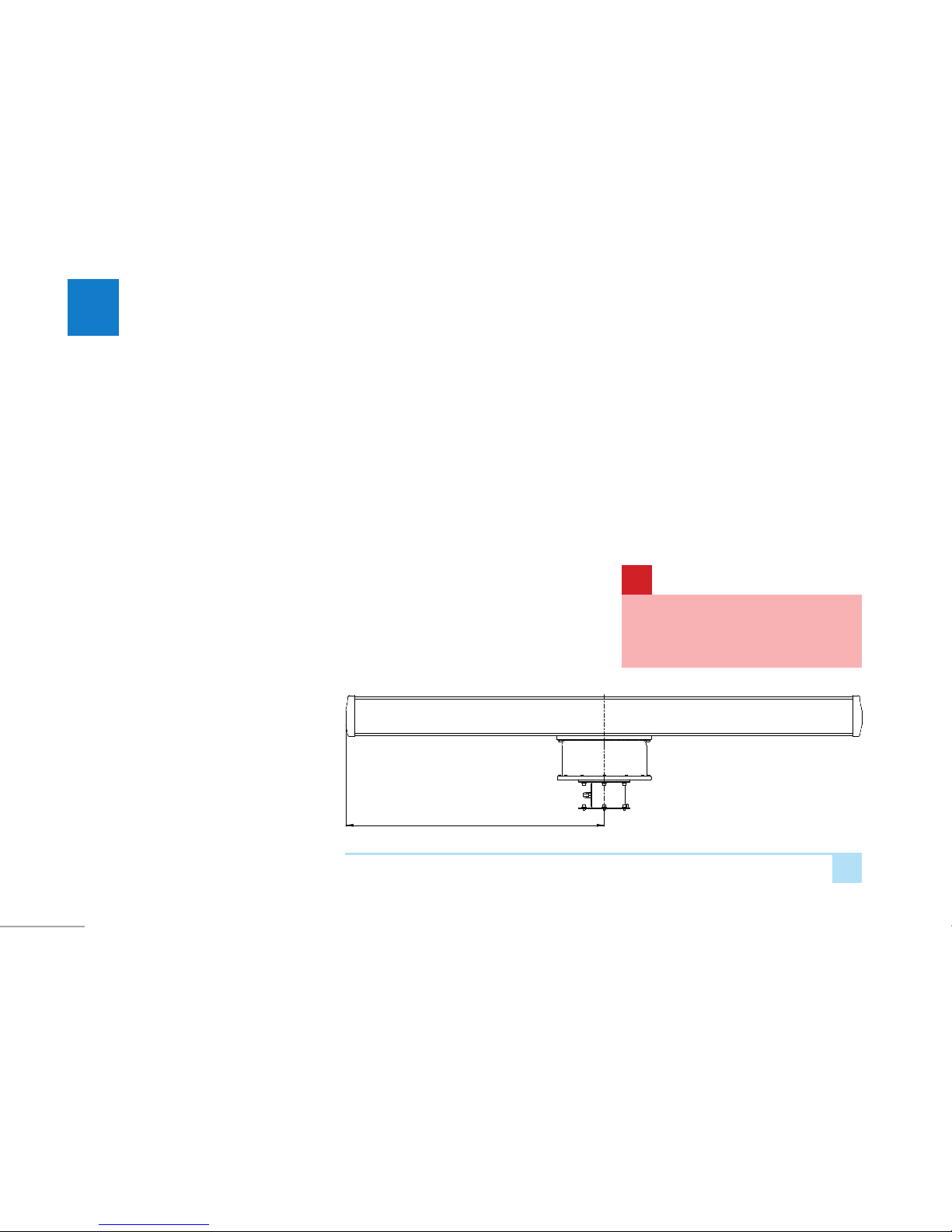
The radar should be installed where it can
perform an unobstructed surveilance of the
designated zone.
2
g.
The antenna sweep radius is 1 m
3
Since no ideal visibility can be achieved for the
whole radar-controlled area, the installation
site should be chosen to maximize coverage
area. Landscape shape, vegetation seasonal
variations, possible interference from land
vehicles, etc. should be taken into account.
Wildlife, vegetation and weather conditions
are also a factor. Shrubs and trees can interfere
with any radar.
1 м
MAKE SURE NOTHING OBSTRUCTS
ANTENNA UNIT ROTATION WHEN
INSTALLING RADAR.
!
To avoid any ghost targets and directional
pattern distortion due to rereflection, it is good
to install radar clear off of planar reflectors
(buildings, fences, large vehicles, other metal
surfaces) at right angle to radar beam.
INSTALLATION

7
Presence of powerful EM sources in radar
directional pattern should be avoided if
possible: other radars (closer than 200 m),
relay stations antennas. etc.
i
Radar elevation is determined by unobstructed
view on the surveilance zone and types of
targets to be detected. Radar proximity to the
ground leads to lower sensibility due to strong
reflections from the ground and to lower view
distance. On the other hand, excess radar
elevation will result in an uncovered area of
ground level.
Optimal elevation of transceiver is 5 to 10
meters above ground.
Installation site must be a rigid platform
with six bores, identical to fastener holes of
MRS-1000-RU. The platform should be pole-
mounted and should not exceed ±5° from
horizontal. The surrounding site should be fall-
safe for personnel to mount and dismout the
radar.
3
g.
Open-air radar installaon
INSTALLATION

8
4
g.
5
g.
200
180 9
6 отв.
INSTALLATION
Installaon of the transceiver unit
Li the antenna unit and the rotaon unit to
the installaon site.
Use template to mark the rigid plaorm prepared
for the installaon of the rotaon unit.
Install the rotaon unit.
200
180 9
6holes
WARNING!
IT IS STRICTLY FORBIDDEN TO USE THE
ANTENNA UNIT FOR SUPPORTING THE
RADAR DURING TRANSPORTATION!
!

9
678
g. g. g.
INSTALLATION
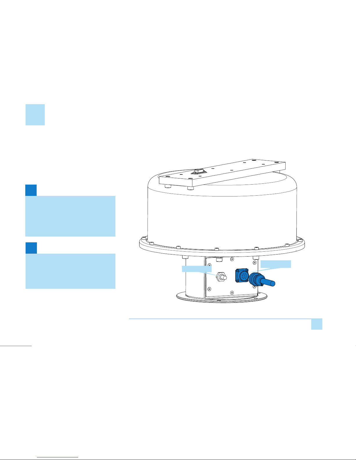
Fasten the rotaon unit rmly using six M8
screws.
Connect the grounding cable to the grounding
screw.
Place the antenna unit onto the rotaon
unit carefully (be sure not to damage the
connector) and fasten it with four M8 screws.
Grounding screw
10
9
g.
Connecng the communicaon cable
Connect the communicaon cable to the
connector of the rotaon unit.
i
i
WARNING!
The minimum cable bending radius must
be at least ve mes the diameter of the
cable. The cables must be protected from
heat and mechanical damage.
WARNING!
Try to avoid laying the interface cable close
to other onboard electrical equipment in
order to reduce electrical interference.
Power switch
Connector
INSTALLATION
11
Communication unit installation
Communication unit should be installed
indoors with temperature range minus 10 to
plus 40 °С.
220 VAC or +24 V power lines should be
provided, as well as Ethernet 100BASE-T line
for data transfer.
Longer distances between radar and its
auxilary equipment should be assisted with
network repeaters if needed.
10
g.
CAUTION!
To avoid mechanical damage to radar
units, make sure there’s no construction
works are held indoors where it should be
installed.
CAUTION!
Make sure there’s no acid vapours and
other corrosive fumes indoors where
radar units are to be installed.
i i
1110
g.g.
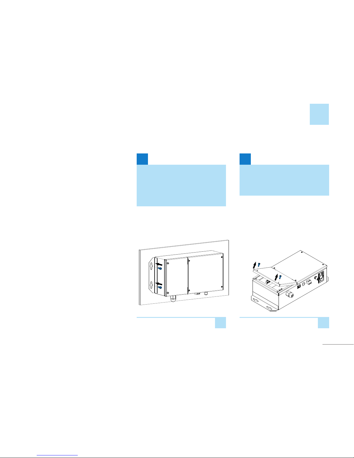
Undo two M3 screws with a HEX2.5 wrench to
remove the protecve cover from the commu-
nicaon unit.
The communicaon unit is installed vercally,
with connectors facing downward. This
posion is required to ensure IP22 protecon.
A power screw driver is used to fasten the
communicaon unit using four screws through
mounng lugs on the side walls of the unit.
INSTALLATION
12
INSTALLATION
13
12
g.
g.
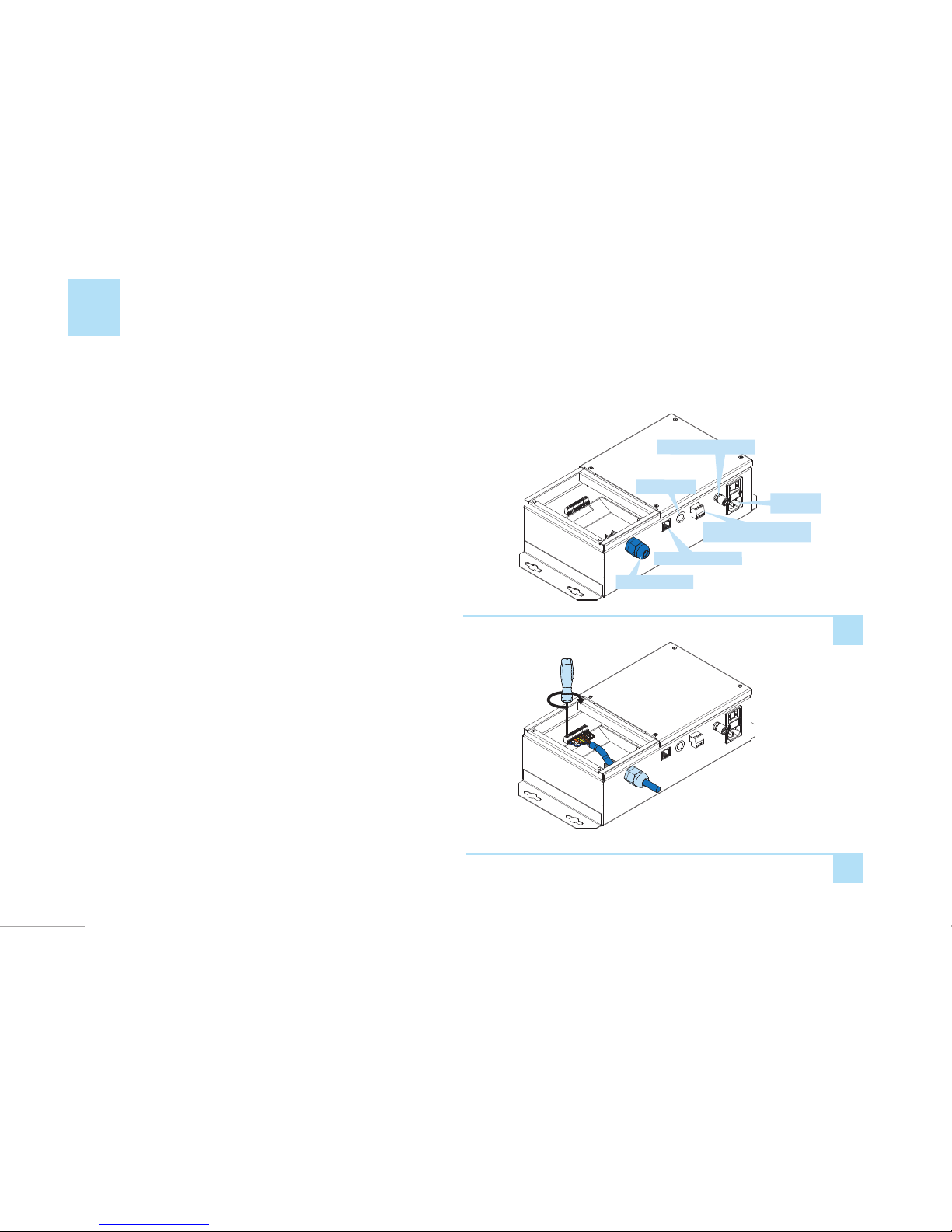
Insert the blue wire into terminal 1 of the
communicaon connector. Tighten the terminal
screw using a SL2.5 at blade screwdriver to x
the wire in the terminal. Connect other wires
according to the wiring diagram in Fig. 14.
Connect the grounding cable to the grounding
terminal.
Loosen the external nut of the cable gland on
the communicaon unit and pass the commu-
nicaon cable through the gland.
220VAC
Fuse 24VDC
24VDC connector
Ethernet connector
Cable gland nut
GND connector
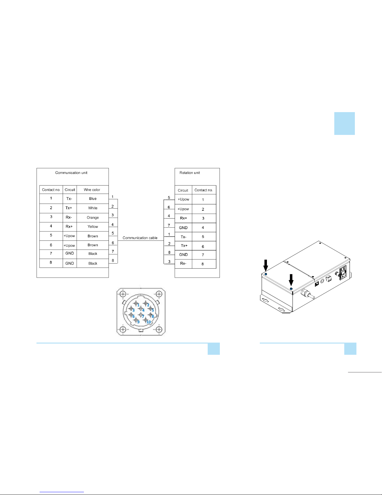
13
14
g.
Wiring diagram (connector front-side view)
Front-side view
15
g.
INSTALLATION
Arrange the cable carefully and x it with
retaining brackets inside the communicaon
unit, then close the protecve cover of
the communicaon unit. Tighten the cable
gland nut and drive in two M3 screws using
a HEX2.5 allen wrench.
14
CONNECTING +24 V POWER
4
16
17
g.
g.
3
2
1
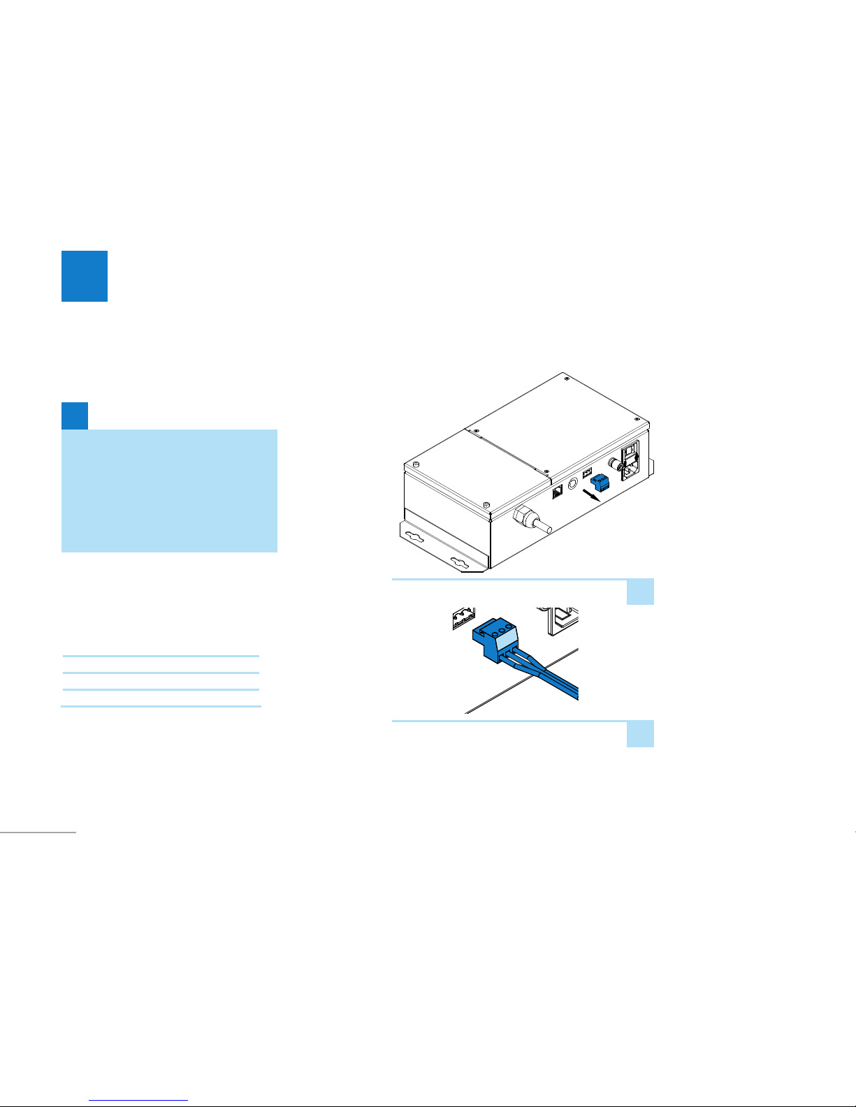
The radar system can be powered from a 24V
DC power source.
In order to switch to the 24V power source,
disconnect the power connectors on
communicaon unit.
Insert the assembled connectors into the
communicaon unit.
Insert power lead wires into connectors
according to the following diagram:
Wire no. Circuit
1 Shield
2 GND
3+24V
WARNING!
When the radar is connected to both
220V and 24V sources, power is supplied
from the 220V source. If the 220V source
loses power, the radar staon switches to
the 24V power source automacally. The
radar staon may also turn o in this case.
i

15
5
TECHNICAL SUPPORT
Should you encounter any problems in the
course of radar operaon, you can contact our
Customer Support.
When making a call, be ready to name your
organizaon owning the radar and the radar
model.
Contact informaon of Technical Support in
Tomsk, Russia:
E-mail: r[email protected]

E-mail: sales@micran.com
Phone: +7 (3822) 900-029, +7 (3822) 413-403,
+7 (3822) 413-406
Fax: +7 (3822) 423-615
Mailing address:
Micran, Kirova Ave., 51d, Tomsk, Russia, 634041
www.micran.com
Table of contents
Other Micran Radar manuals

Popular Radar manuals by other brands


Endress+Hauser
Endress+Hauser FOUNDATION Fieldbus Micropilot FMR56 Brief operating instructions

Honeywell
Honeywell PRIMUS 660 Pilot's manual

KROHNE
KROHNE OPTIFLEX 2200 C Supplementary instructions

Carmanah
Carmanah SpeedCheck-15 install guide

Kustom Signals
Kustom Signals DRU III Operator's manual

Magnetrol
Magnetrol eclipse 705 Safety manual

Sensors & Software
Sensors & Software Noggin 100 user guide

Raytheon
Raytheon R10X instruction manual

Continental Refrigerator
Continental Refrigerator RightViu Mounting instructions

Hesai
Hesai Pandar40M user manual

Endress+Hauser
Endress+Hauser Hart Micropilot FMR60B operating instructions

Endress+Hauser
Endress+Hauser Levelflex FMP53 operating instructions