Micran MRS-1000-AU User manual

DOCUMENT VER. 1.0
AUGUST 2015
MRS-1000 RADAR SYSTEM
USER
MANUAL

2
CONFIGURATION
3
FEATURES
4
GENERAL INFORMATION
5
5
5
5
6
8
8
8
9
9
SPECIFICATIONS 10
DELIVERY SET 11
TECHNICAL SUPPORT 12
1
3
4
5
6
2

3
The MRS-1000 radar system is designed around
X-band radar and consists of the following units:
Outdoor equipment:
Radar (Antenna MRS-1000-AU and
Indoor equipment:
CONFIGURATION
1
CAUTION!
-
i
Basic Conguraon Components
Power supply
4
FEATURES
Radar uses FMCW (Frequency Modulated Con-
-
-
maintenance. Thus the radar image is the same
as that of the magnetron radar.
Timing diagram of FMCW signal
Radar transmits a signal of increasing fre-
to a target.
MRS-1000 TECHNICAL DESCRIPTION Page 7of 15
SYSTEM OVERVIEW
ABOUT FREQUENCY MODULATED CONTINUOUS WAVE (FMCW)
MRS-1000 Radar uses FMCW (Frequency Modulated Continuous Wave) radar technology. The
main distinguishing feature of broadband radar unlike traditional pulsed radars is solid-state
element base instead of the magnetron, which significantly increases the MTBF without
additional maintenance. Thus the radar image is the same as that of the magnetron radar.
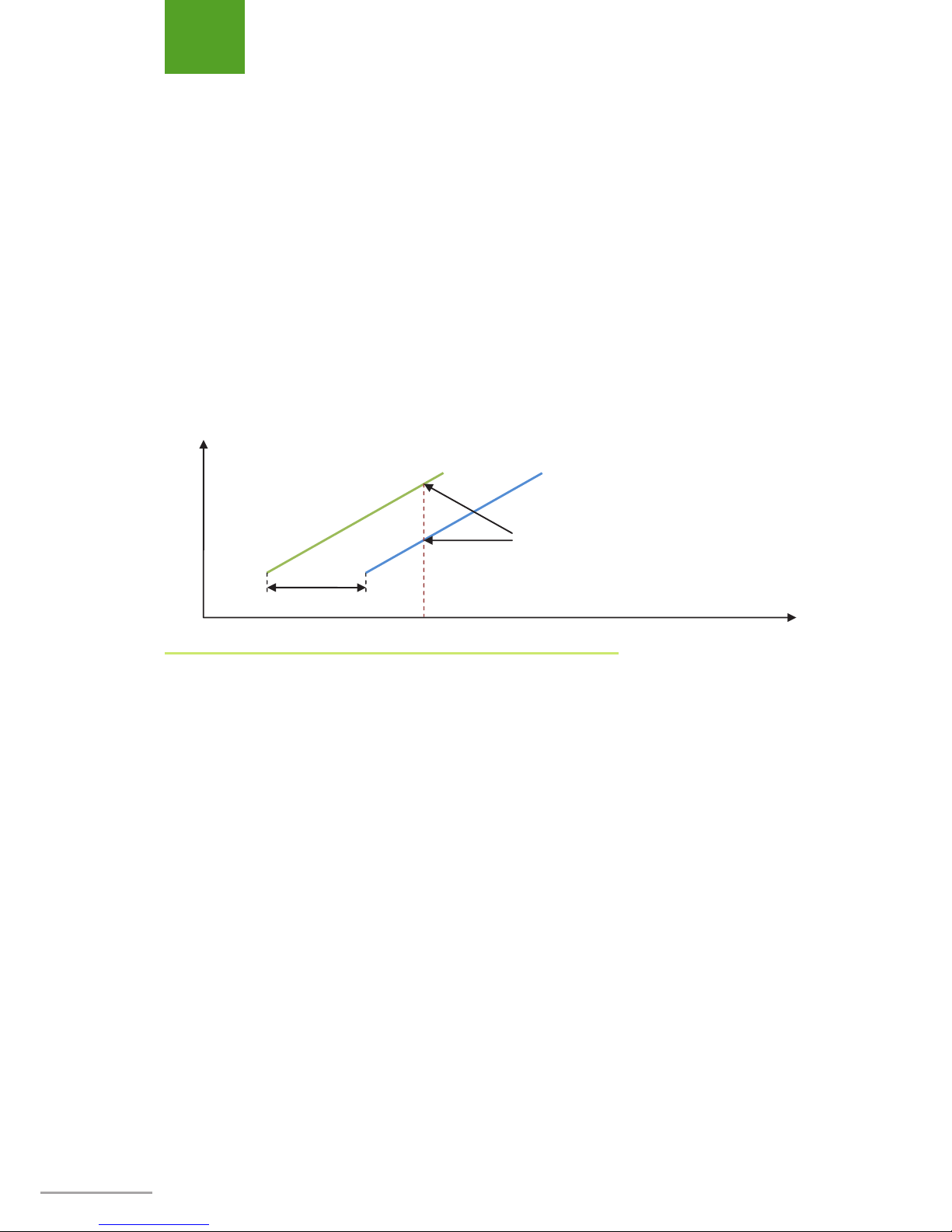
Radar transmits a signal of increasing frequency. Measuring the difference between the current
transmitted frequency and echoed frequency allows to calculate the time of the returned echoes
and, as a result, the distance to a target.
Fig. 1 Timing diagram of FMCW signal
Frequency
Time
Transmitted signal
Received signal
In each moment frequency of transmitted signal is
higher than frequency of received signal
Reflection time
2

5
3
GENERAL INFORMATION
SAFETY PRECAUTIONS
-
-
ters.
NO PERSONNEL SHALL BE ALLOWED TO
REMAIN IN THE NEAR VICINITY OF THE
SYSTEM’S ANTENNA UNIT WHEN THE
TRANSMITTER IS SWITCHED ON AND
WORKING ON AIR!
DEN TO:
OPEN ITS COMPONENTS OR REPLACE
DISCONNECT OR RECONNECT COM
USING MEASURING INSTRUMENTS
AND ACCESSORIES THAT HAVE NOT
BEEN DULY CERTIFIED.
!
!
INSTALLATION AND REMOVAL
Manual.
IT IS PROHIBITED TO APPLY ADHESIVE
FILM TO OR PAINT THE ANTENNA UNIT
HOUSING!
!
MAINTENANCE
-
-
-
facturing plant.
-
-
-
CAUTION!
-
-
nect it from the 24 V electrical system.
CAUTION!
i
i

6
power supply circuits in the following units:
1.
of the 24 VDC electrical system.
2.
3.
connector.
4.
FUSE REPLACEMENT
соединения, согласно
инструкции на компас
Устройство не подключено
Анемометр
Проверьте
правильность
соединения, согласно
инструкции на
анемометр
Устройство не подключено
GPS
Проверьте
правильность
соединения, согласно
инструкции на GPS
Устройство не подключено
Эхолот
Проверьте
правильность
соединения, согласно
инструкции на эхолот
Устройство не подключено
ЛАГ
Проверьте
правильность
соединения, согласно
инструкции на ЛАГ
Устройство не подключено
Анемометр
Проверьте
правильность
соединения, согласно
инструкции на АИС
Сбой канала Тх
Проверьте соединения
кабелей антенны
Превышен лимит КСВН
антенны
Потеряна внешняя система
позиционирования
Проверьте
подключение GPS к
АИС в соответствии с
эксплуатационной
документации на эти
устройства.
Отсутствует система
позиционирования
Нет данных о скорости судна
Замена предохранителей
В станции предусмотрены предохранители, для защиты цепей питания в
следующих блоках:
- мотор-редукторе (цепь питания 24В);
- блоке сопряжения (цепи питания от бортовой сети и сети 220В);
- блоке управления и индикации (цепи питания от бортовой сети и сети
220В).
Методика замены предохранителя в мотор-редукторе
1. Отключите питание на блоке сопряжения переводом выключателя
питания 220В в положение «ОТКЛ» (если блок запитан от сети
~220В) или отключите разъем питания бортовой сети 24В.
2. Переведите тумблер питания на мотор-редукторе в положение
«ОТКЛ».
3. Отключите кабель от разъема Мотор-редуктора.
4. Открутите шесть винтов М4 на крышке Мотор-редуктора. Аккурат-
но отодвиньте ее в сторону.
5. -
nector arranged on the board. Replace the
fuse with a new one.
6.
7.
the ON/OFF toggle switch to the ON posi-
1 – Fuse Holder
CAUTION!
The new fuse shall comply with the follow-
ing requirements:
• Fusible link, for cars, mini format
• Rated current of 7.5 A.
i
1
GENERAL INFORMATION
M4 screws
Connector

7
-
placement
If powered from 24VDC power supply circuit:
1. Detach 24VDC connector of the electrical
system.
2.
3.
4. Replace the fuse with a new one.
5. Insert the 24VDC fuse holder into the unit
6.
system.
If powered from the electrical system of
220VAC:
1. Set the 220VAC power switch to the OFF
2. Detach 220VAC power connector of the
electrical system.
CAUTION!
The new fuse shall comply with the follow-
ing requirements:
• Cylindrical fuse link measuring 5x20
• Rated current of 5 A.
CAUTION!
The new fuse shall comply with the follow-
ing requirements:
• Cylindrical fuse link measuring 5x20
• Rated current of 2 A.
i i
3.
4. Replace the fuse with a new one.
5. Insert the 220VAC fuse holder into the unit.
6.
system.
GENERAL INFORMATION

8
GENERAL INFORMATION
TRANSPORTATION
arranged and secured in accordance with the
-
face shall be inscribed with the appropriate in-
-
STORAGE
-
side unheated storage premises at a tempera-
-
per one year of storage. The storage term of a
-
The ambient air in storage premises shall be free
-
OPERATING LIMITATIONS
-
Value Value
+55 +40
-40 -10
CAUTION!
Do not allow underwater submersion of
MRS-1000!
i

9
DISPOSAL
poisonous substances posing threat to human
-
Disposal of the radar can be performed in ac-
cordance with the disposal rules established for
general-purpose industrial wastes.
shall be disposed of by special agencies autho-
-
cal law.
GENERAL INFORMATION
MANUFACTURER’S WARRANTY
The Manufacturer guarantees compliance of
-
2 years from the date of its acceptance by the
user.

10
SPECIFICATIONS
12 to 24
3
1°
3.5
100
1
1°
30°
4
+17 to +27
Parameters of 220 VAC power supply system
47.5 to 52.5
100
Data interface Ethernet 100Base-T
4

11
DELIVERY SET
dimensions
Qty
Antenna Unit MRS-1000-AU 10.5 1
16 1
2.5 20 m 1
3 1
- 1
- 1
SPTA set - 1
5

12
TECHNICAL SUPPORT
Should you encounter any problems in the
Customer Support.
model.
E-mail:
6

13

Mailing address:
www.micran.com
This manual suits for next models
4
Table of contents
Other Micran Radar manuals


