M-system HDMS User manual

HDMS FMCW RADAR – USER MANUAL
RevisionNumber : 1.30
Date : October 01, 2021
Writer : Lee Je Woo
This document contains all the resources needed to set up the HDMS FMCW RADAR for performance evaluation.
User's Guide
HDMS – HDMS FMCW RADAR
User's Guide

Aftermarket – HDMS FMCW RADAR
PAGE - 2 -
Revision history
Project Manager ----
Tec hn ol og y ----
Quality ----
Production ----
Date Description Name Note
21.10.01 최초작성 이제우 V1.00
21.11.15 IC, FCC, CE RED_EC 추가 이제우 V1.10
21.12.27 공급업체 관련 코멘트 추가 이제우 V1.20
22.01.03 동작전압, 주파수, RF Power 관련 내용 수정 이제우 V1.30

Aftermarket – HDMS FMCW RADAR
PAGE - 3 -
List
RADAR (Radio Detection and Ranging)? .................................................................................................... 4
1.1 Detailed Specifications ...................................................................................................................... 5
1.2 About RADAR antennamodule measurement ranges and beam patterns ........................................ 6
2 Components ............................................................................................................................................ 9
2.1 IP6K7 RADAR ................................................................................................................................... 9
2.2 RADAR Bracket ................................................................................................................................. 9
2.3 Connect cable .................................................................................................................................. 10
2.4 Power supply and PC connection. ................................................................................................... 15
3 Communication Protocol ....................................................................................................................... 16
4 RADAR Installation and Test Procedure ............................................................................................... 18
4.1 RADAR Test Compliance ................................................................................................................ 18
4.2 RADAR Installation Compliance ...................................................................................................... 18
4.3 RADAR Test Method (How to Use a Tripod) ................................................................................... 19
4.4 RADAR Test Method (How to Use in Vehicle) ................................................................................. 19
5. Appendix ................................................................................................................................................ 20
Interference Mitigation For IWR1443 RADAR Device ............................................................................... 20
1 Types of Interference in FMCW RADAR ............................................................................................... 20
2 Interference Avoidance .......................................................................................................................... 20

Aftermarket – HDMS FMCW RADAR
PAGE - 4 -
1 RADAR (Radio Detection and Ranging)?
- It is a device that measures the distance or shape
to an object by radiating strong electromagnetic
waves and measuring reflected waves reflected by
the object.
- Compared to other sensors, it has higher
permeability (lower impact on clouds and weather)
and can detect long distances.
- The Frequency Modulated Continuous Wave
(FMCW) method is mostly used, the hardware
configuration is easier than other modulation
methods, and it has high resolution and speed
resolution in terms of performance.
- HDMS FMCW RADAR is a RADAR with a 77 ~
81Ghz frequency band and is installed in heavy
equipment with stable and excellent performance
and is used to detect people.
- It is installed in heavy equipment and can be
expected to reduce injuries and accident rates due
to collision prevention and prevention with RADAR
and reduce the cost of human and material
resources due to accident prevention.
- RADAR data output information is as follows.
Distance(X,Y Coordinates)
Object Signal Power

Aftermarket – HDMS FMCW RADAR
PAGE - 5 -
1.1 Detailed Specifications

Aftermarket – HDMS FMCW RADAR
PAGE - 6 -
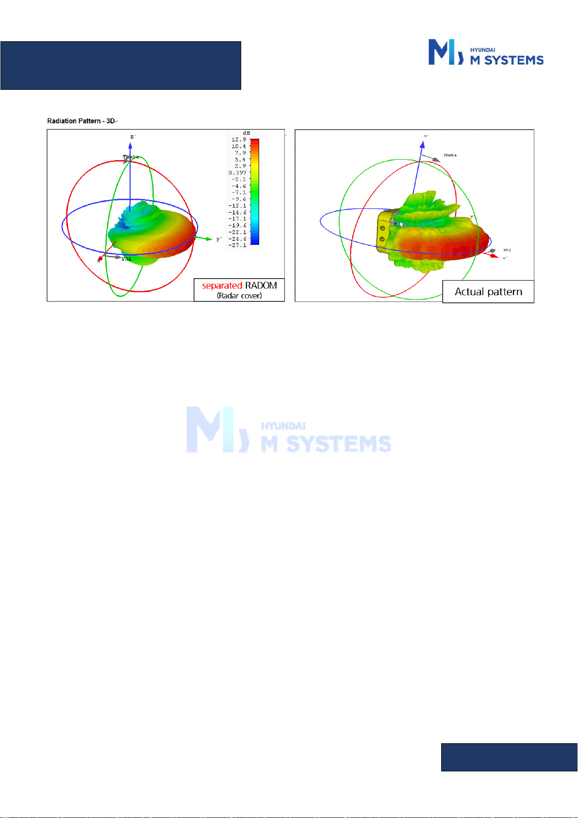
1.2 About RADAR antennamodule measurement ranges and beam patterns
- RADAR's beam pattern computer simulation image is as follows, and RADAR’s beam pattern is different
depending on the presence or absence of a cover of the case.
RADAR Antenna Module, Detecting Range, Azimuth Pattern
Aftermarket – HDMS FMCW RADAR
PAGE - 7 -
RADAR Antenna Module beam radiation pattern
(Left: Top case remove, Right: Top case)
> This device complies with part 15 of the FCC Rules. Operation is subject to the following two
conditions: (1) This device may not cause harmful interference, and (2) this device must accept
any interference received, including interference that may cause undesired operation.
> This equipment has been tested and found to comply with the limits for a digital device, pursuant
to part 15 of the FCC Rules. These limits are designed to provide reasonable protection against
harmful interference in a residential installation. This equipment generates, uses and can radiate
radio frequency energy and, if not installed and used in accordance with the instructions, may
cause harmful interference to radio communications. However, there is no guarantee that
interference will not occur in a particular installation. If this equipment does cause harmful
interference to radio or television reception, which can be determined by turning the equipment
off and on, the user is encouraged to try to correct the interference by one or more of the
following measures:
- Reorient or relocate the receiving antenna.
- Increase the separation between the equipment and receiver.
- Connect the equipment into an outlet on a circuit different from that to which the receiver
is connected.
- Consult the dealer or an experienced radio/TV technician for help
Changes or modifications not expressly approved by the party responsible for compliance
could void the user's authority to operate the equipment.

Aftermarket – HDMS FMCW RADAR
PAGE - 8 -
This device should be installed and operated with minimum 20 cm between the radiator and
your body.
Prohibited applications of RADAR equipment under this service rule include fixed RADAR use
outside of airport areas and airborne RADAR operations.
- This device can be operated in at least one Member State without infringing applicable
requirements on the use of radio spectrum.

Aftermarket – HDMS FMCW RADAR
PAGE - 9 -
2 Components
2.1 IP6K7 RADAR
- RADAR product is composed in detail as follows.
Top C as e, B ot to m Ca se
Connect Cables
Interface board, RADAR Antenna module
IP6K7 RADAR(24RA-20000)
2.2 RADAR Bracket
RADAR Bracket, assembly screws
- Bracket is used to fix RADAR in a specific position.
- Four M8 screws are used to fix the bracket and RADAR.

Aftermarket – HDMS FMCW RADAR
PAGE - 10 -
2.3 Connect cable
- The basic configuration for RADAR and the connection cable is as follows.
- Refer to the table below and the image for the pin configuration of the connection cable TE 1-
1703506-1 of RADAR.
[커넥터 전면부] [커넥터 Pin 번호]
PIN Pin Description
1 Power(24V)
2 GND
3 CAN HIGH
4 CAN LOW
5 Reserved
6 Digital Input1
7 Digital Input2
8 Digital Input3
장착 위치 CAN ID
GPIO 입력 값(0:Low, 1:High)
PIN 6
(Radar ID 1)
PIN 7
(Radar ID 2)
PIN 8
(Radar ID 3)
Install_Position_0 0x18FF326C Open/GND Open/GND Open/GND
Install_Position_1 0x18FF326A Open/GND Open/GND 24v
Install_Position_2 0x18FF3268 Open/GND 24v Open/GND
Install_Position_3 0x18FF326B Open/GND 24v 24v
Install_Position_4 0x18FF3269 24v Open/GND Open/GND
This manual suits for next models
1
Table of contents
Popular Radar manuals by other brands

SAW D2L
SAW D2L Valentine One Gen2 owner's manual

Raymarine
Raymarine Raytheon R20X instruction manual

Simrad
Simrad CA34 manual

Endress+Hauser
Endress+Hauser Micropilot FMR67B Brief operating instructions

Endress+Hauser
Endress+Hauser Levelflex M FMP45 operating instructions

ECHOMAX
ECHOMAX Active-X-Band manual


