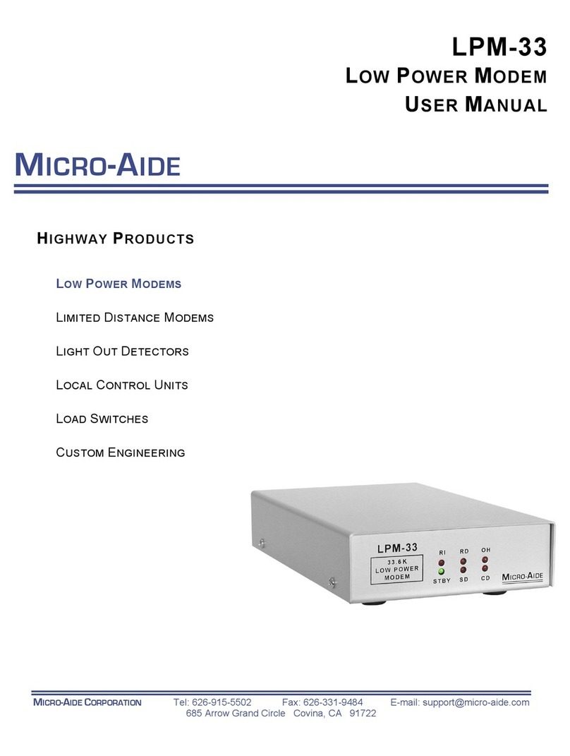
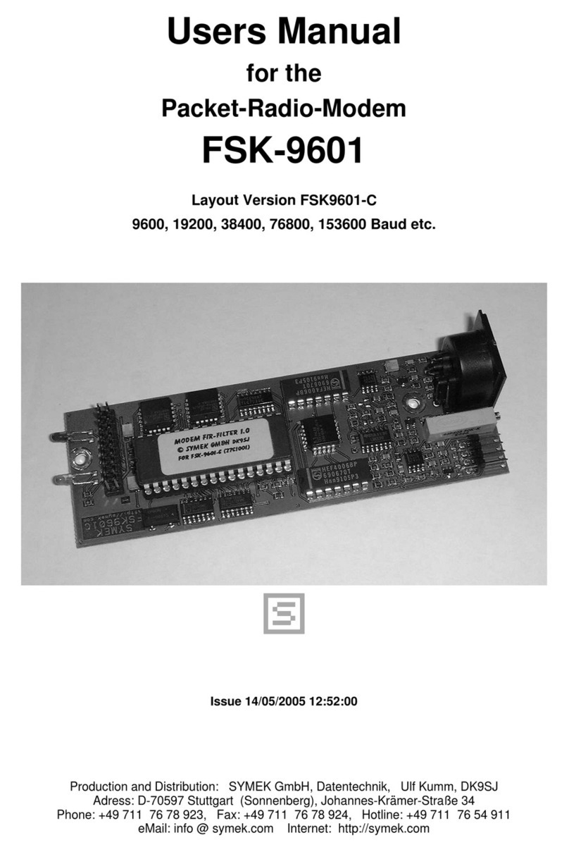
Micro-Aide LDM-1 standlalone User manual

LIMITED DISTANCE MODEM
USER MANUAL
by MICRO-AIDE CORP.

.

LIMITED DISTANCE MODEM
USER MANUAL
MICRO-AIDE CORP.
626-915-5502 s[email protected]
Revised: June 16, 2009
A comprehensive document for the following LDM products:
• LDM-1 standlalone
• LDM-1 plug-in
• LDM-16 nest

Copyright © 2007 by MICRO-AIDE Corporation
All rights reserved. No part of this document may be reproduced or transmitted in any form
or by any means without the written permission of MICRO-AIDE Corporation.
The information in this document is subject to change without notice. MICRO-AIDE believes
the information contained in this document to be accurate. However, MICRO-AIDE assumes
no responsibility for any errors or omissions.
Windows, Windows 98 and Windows XP are registered trademarks of Microsoft Corporation.

iii
TABLE OF CONTENTS
CHAPTER 1GENERAL DESCRIPTION
Introduction. . . . . . . . . . . . . . . . . . . . . . . . . . . . . . . . . . . 1
Key Features . . . . . . . . . . . . . . . . . . . . . . . . . . . . . . . . . . 2
About This Manual . . . . . . . . . . . . . . . . . . . . . . . . . . . . . . . 2
Revision Level . . . . . . . . . . . . . . . . . . . . . . . . . . . . . . . 3
TxDOT Applications. . . . . . . . . . . . . . . . . . . . . . . . . . . . 3
CHAPTER 2SETUP AND INSTALLATION
Introduction. . . . . . . . . . . . . . . . . . . . . . . . . . . . . . . . . . . 5
Unpacking . . . . . . . . . . . . . . . . . . . . . . . . . . . . . . . . . . . . 7
LDM-1 Basics . . . . . . . . . . . . . . . . . . . . . . . . . . . . . . . . . . 8
Network Types . . . . . . . . . . . . . . . . . . . . . . . . . . . . . . . . . 9
Point-to-Point . . . . . . . . . . . . . . . . . . . . . . . . . . . . . . . 9
Multi-drop Network . . . . . . . . . . . . . . . . . . . . . . . . . . . .10
Accessing the LDM-1 PCB . . . . . . . . . . . . . . . . . . . . . . . . . . .12
User Configured Settings . . . . . . . . . . . . . . . . . . . . . . . . . . . .12
Setup . . . . . . . . . . . . . . . . . . . . . . . . . . . . . . . . . . . . . .13
Rcv and Xmt Terminations (AX1 and AX2). . . . . . . . . . . . . . . .13
Enable Xmt Channel Busy Detector (AX3) . . . . . . . . . . . . . . . .14
RS-232 Protective Ground (AX5) . . . . . . . . . . . . . . . . . . . . .14
RTS to CTS Delay (SW2) . . . . . . . . . . . . . . . . . . . . . . . . .14
Equalization (SW3) . . . . . . . . . . . . . . . . . . . . . . . . . . . . .14
Permanently Asserting the RTS . . . . . . . . . . . . . . . . . . . . . .15
Installation . . . . . . . . . . . . . . . . . . . . . . . . . . . . . . . . . . .15
LDM-1 Standalone . . . . . . . . . . . . . . . . . . . . . . . . . . . . .15
LDM-1 Plug-in . . . . . . . . . . . . . . . . . . . . . . . . . . . . . . .16
LDM-16 Nest. . . . . . . . . . . . . . . . . . . . . . . . . . . . . . . .16
Attaching the Network Lines. . . . . . . . . . . . . . . . . . . . . . . .17
Connecting to the DTE . . . . . . . . . . . . . . . . . . . . . . . . . .17
CHAPTER 3OPERATION
Introduction. . . . . . . . . . . . . . . . . . . . . . . . . . . . . . . . . . .19
Indicators and Controls . . . . . . . . . . . . . . . . . . . . . . . . . . . . .19
LEDs . . . . . . . . . . . . . . . . . . . . . . . . . . . . . . . . . . . .19

LDM User Manual
iv
Select Mode Pushbutton Switch . . . . . . . . . . . . . . . . . . . . . . 20
Operating Modes . . . . . . . . . . . . . . . . . . . . . . . . . . . . . . . . 20
Normal Mode . . . . . . . . . . . . . . . . . . . . . . . . . . . . . . . 21
Test Mode A - Analog test with digital loop back . . . . . . . . . . . . . 22
Test Mode B - Analog loop back with DTE data . . . . . . . . . . . . . 22
Test Mode C - Analog loop back with test data . . . . . . . . . . . . . . 23
CHAPTER 4MAINTENANCE
Introduction . . . . . . . . . . . . . . . . . . . . . . . . . . . . . . . . . . 25
PCB Removal and Insertion . . . . . . . . . . . . . . . . . . . . . . . . . . 25
Jumper and Switch Locations . . . . . . . . . . . . . . . . . . . . . . . . . 26
Trouble-Shooting Guide . . . . . . . . . . . . . . . . . . . . . . . . . . . . 27
APPENDIX ATECHNICAL DATA
LDM-1 Specifications . . . . . . . . . . . . . . . . . . . . . . . . . . . . . 29
LDM-16 Specifications . . . . . . . . . . . . . . . . . . . . . . . . . . . . . 30
Transmission Range Specifications. . . . . . . . . . . . . . . . . . . . . . . 30
Recommended Equalizations Settings . . . . . . . . . . . . . . . . . . . . . 31
DB-25 Connector Wiring . . . . . . . . . . . . . . . . . . . . . . . . . . . 31
APPENDIX BTXDOT APPLICATIONS
Introduction . . . . . . . . . . . . . . . . . . . . . . . . . . . . . . . . . . 33
Network Configurations . . . . . . . . . . . . . . . . . . . . . . . . . . . . 33
Point-to-Point . . . . . . . . . . . . . . . . . . . . . . . . . . . . . . . 33
Multi-Drop . . . . . . . . . . . . . . . . . . . . . . . . . . . . . . . . . 34
RS-232 Cables . . . . . . . . . . . . . . . . . . . . . . . . . . . . . . . . . 34
LCU to LDM-1 . . . . . . . . . . . . . . . . . . . . . . . . . . . . . . 34
PSDM to LDM-1 . . . . . . . . . . . . . . . . . . . . . . . . . . . . . 34
ADU to LDM-1 . . . . . . . . . . . . . . . . . . . . . . . . . . . . . . 34
Test Software . . . . . . . . . . . . . . . . . . . . . . . . . . . . . . . . . . 35
Requirements. . . . . . . . . . . . . . . . . . . . . . . . . . . . . . . . 35
Installation . . . . . . . . . . . . . . . . . . . . . . . . . . . . . . . . . 35
Test Procedure . . . . . . . . . . . . . . . . . . . . . . . . . . . . . . . 36

1
CHAPTER 1
GENERAL DESCRIPTION
INTRODUCTION
MICRO-AIDE’s family of Limited Distance Modem (LDM) products can be
used in a variety of data communications applications. The family consists of
the following products.
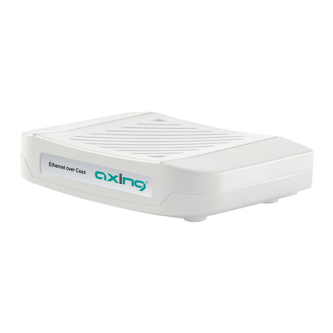
•LDM-1 standalone - a complete LDM (photographed on the cover page of
this manual).
•LDM-1 plug-in - functionally identical to the standalone version, it is a
printed circuit board (PCB) that is mounted within the LDM-16 nest.
•LDM-16 nest - a 19" rack-mounted chassis that can be equipped with 1 to
16 LDM-1 plug-in PCBs.
The LDM-1 can be thought of as a device for extending RS-232 communica-
tions over great distances (e.g., thousands of feet). It serves as an interface
between the customer’s Data Terminal Equipment (DTE) and data communi-
cations network. It is designed to be compatible with four-wire, private line
networks. It can be used to facilitate point-to-point and multi-drop network
configurations. Its unique performance characteristics permit data transmis-
sion and reception over distances of many miles. Additionally, the LDM-1 will
operate over a wide temperature range.

LDM User Manual
2
The LDM-1 is easy to install and operate. Several self-test modes allow the
user to verify its performance and network segment integrity. Light Emitting
Diode (LED) indicators inform the user of all critical functions.
KEY FEATURES
Listed below are just a few of the features associated with MICRO-AIDE’s
family of LDM products.
• Broad transmission range, up to 25 miles, point-to-point, at 4800Baud.
• Data transparent transmission and asynchronous operation.
• Baud rates from 75 to 19,200.
• Supports multi-drop configurations of up to eight LDM-1s. Transmission
distance and data rate performance are not de-rated by adding drop points.
• Standard DB-25 female connector provides simple cabling to any RS-232
device.
• Easy-to-activate analog and digital loop back test modes.
• Includes transmit channel detector to avoid data transmission collisions.
Data contention can be resolved at the LDM-1, not at the DTE.
• Allows full duplex operation on four wires.
• Compact size, LDM-1 standalone footprint is approximately 5" by 8" and
less than 2lbs. in weight.
• LDM-16 nest can be equipped with 1 to 16 LDM-1 plug-in PCBs for appli-
cations requiring multiple network interfaces at a single location.
ABOUT THIS MANUAL
This document is intended to provide the user with comprehensive, easy-to-
read instructions on how to install, set up, operate and maintain all three
LDM products. Wherever possible, step-by-step instructions are listed. In the
event the user has questions about any of the described procedures the user
should contact MICRO-AIDE for assistance.

General Description - About This Manual
3
MICRO-AIDE Corp.
685 Arrow Grand Circle, Covina, CA 91722
Tel: 626-915-5502 Fax: 626-331-9484
E-mail: [email protected]
The MICRO-AIDE Material Return and Limited Warranty policies can be
found on the inside back cover of this manual.
REVISION LEVEL
This User Manual makes specific reference to Revision D of the LDM-1.
Additionally, this manual is applicable to LDM-1s that have been factory
reworked to the Revision D level. The revision level can be found near the
lower right-hand corner of the LDM-1’s printed circuit board (PCB).
TXDOT APPLICATIONS
The LDM products are frequently used with MICRO-AIDE’s Local Control
Unit (LCU) and other data communications devices throughout the State of
Texas. They have been approved by the Texas Department of Transportation
for use in various highway communications networks. Appendix B includes
information specific to these applications.

LDM User Manual
4
USER NOTES

5
CHAPTER 2
SETUP AND INSTALLATION
INTRODUCTION
This chapter describes how to properly unpack, set up and install each of the
MICRO-AIDE LDM products. Typical point-to-point and multi-drop net-
work installations are described.
Figure 1 on page 6 includes an illustration of the front and rear panels of the
LDM-1 standalone modem. The LDM-16 nest is illustrated in Figure 2 on
page 7.
NOTE: Unless otherwise stated, the term LDM-1 will refer to either version
of the modem (i.e., LDM-1 standalone and LDM-1 plug-in).
TIP: The LDM-1 must be properly configured before it can be put into
operation. As the setup procedure requires that the user have access to the
LDM-1 PCB, it is advisable that the user complete the setup procedure
described herein and then proceed to install the modem.

LDM User Manual
6
Figure 1 - LDM-1 Standalone

Setup and Installation - Unpacking
7
UNPACKING
The LDM-1 standalone and LDM-16 nest are packed in individual containers
that are properly sized for the unit. The LDM-1 plug-in PCBs are secured
inside the LDM-16 nest. Abundant packing materials are provided to mini-
mize mechanical shock to the contents. Before opening the shipping carton
inspect the carton for damage. Damage to the container should be noted.
Carefully remove the unit. It is advisable to save all packing materials in the
event the unit ever needs to be returned to MICRO-AIDE.
Inspect each unit and PCB for any visual damage. The unit should not be
scratched, dented or deformed in any way. If it appears that the unit was dam-
aged in shipment the responsible carrier should be notified immediately.
MICRO-AIDE will assist the user in filing a claim in the event damage was
sustained during shipment.
Figure 2 - LDM-16 Nest

LDM User Manual
8
LDM-1 BASICS
The LDM-1 can be thought of as a device that extends the distance that
RS-232 serial data can be transmitted and received. It does so over four-wire
(i.e., two pair) private line networks. It includes a standard DB-25 female con-
nector that allows for direct connection to any DTE device. The LDM-1 is
configured as a DCE device. Refer to Figure 7 on page 31.
Regardless of the network configuration (refer to section entitled “Network
Types” on page 9) at least two modems must be used. The master modem
broadcasts to one or more slave modems. Each slave modem listens to the
data on its receive channel and passes that data to its DTE device. Under con-
trol of its DTE device only one of the slave modems is allowed to respond at
a time to the master modem’s message. The slave modem sends data via its
transmit channel.
The basic transmit and receive methodology employed is summarized by the
following rules.
• Only one master modem can be employed per network.
• The master modem broadcasts simultaneously to every slave modem.
• Only one slave modem can respond to the master modem at a time. It can
only transmit data to the master modem (i.e., not to another slave modem).
• The slave DTE device, via its application, controls the response of each
slave modem.
• Hardware flow control must be enabled within each DTE device. Specifi-
cally, the DTE device must not attempt to send data until its modem has
asserted its Clear to Send (CTS) signal.
• If only two modems are used, as is the case in a point-to-point network, the
RTS signal of each modem can be permanently asserted. Refer to the section
entitled “Permanently Asserting the RTS” on page 15.
NOTE: The LDM-1 (master or slave) will only transmit data when its
Request to Send (RTS) signal is asserted and the LDM-1 has in response
asserted its CTS signal.

Setup and Installation - Network Types
9
NETWORK TYPES
The LDM-1 has several options and performance settings that can be config-
ured by the user. Equalization, line termination and timer settings are among
the various items. Before the LDM-1 can be properly set up the type of net-
work that will be used must be understood and selected. The LDM-1 is
designed for use in point-to-point and multi-drop networks. They are
described in the following two sections.
POINT-TO-POINT
The point-to-point network is the simplest of the two configurations. It is
characterized by a two-pair cable and a single modem at each cable end. The
cable pairs are referred to as Xmt and Rcv for transmit and receive, respec-
tively. Figure 3 on page 10 illustrates a typical point-to-point network.
The proper LDM-1 setup configuration for a point-to-point network is as fol-
lows:
• The Xmt and Rcv Terminations for both modems must be set to On.
• Since only two modems are used, the RTS signal of each modem can be per-
manently asserted. Refer to the section entitled “Permanently Asserting the
RTS” on page 15.
• The end-to-end cable length must not exceed the recommendations as listed
in Table 5 on page 30 for the given cable diameter and selected Baud rate.
• The Equalization setting for both modems must be identical and set in
accordance with the recommendations as listed in Table 6 on page 31.
WARNING: The LDM-1 cannot be used in a star network configuration
involving spoke lengths that are greater than 100ft.

LDM User Manual
10
MULTI-DROP NETWORK
The multi-drop network involves two or more, two-pair cable segments. Each
cable segment includes a Xmt and Rcv cable pair. The ends of the cable are
connected to a single modem. These modems are also referred to as the near-
and far-end modems. The master modem is located at the near end. The far
end is equipped with a slave modem. The intersection of two cable segments
forms a drop point. A slave modem can be connected to the network at each
drop point. Figure 4 on page 11 illustrates a typical multi-drop network.
The proper setup configuration for a multi-drop network is as follows:
• The Xmt and Rcv Terminations for the near- and far-end modems must be
set to On.
• The Xmt and Rcv Terminations for each modem at a drop point must be set
to Off.
Figure 3 - Typical Point-to-Point Network
NOTE: A multi-drop network is limited to no more than eight modems.

Setup and Installation - Network Types
11
• The RTS signal of the master modem can be permanently asserted. Refer to
the section entitled “Permanently Asserting the RTS” on page 15.
• RTS-CTS flow control must be used by each DTE device connected to a
slave modem.
• The near- to far-end cable length must not exceed the recommendations as
listed in Table 5 on page 30 for the given cable size and selected Baud rate.
• The Equalization setting for the near- and far-end modems must be identical
and set in accordance with the recommendations as listed in Table 6 on
page 31. Assume a cable length equal to the near-end to far-end cable length.
• The Equalization setting for a drop point modem must also be set in accor-
dance with the recommendations as listed in Table 6 on page 31. Assume a
cable length equal to the length between the near-end modem (i.e., master)
and the drop point modem.
Figure 4 - Typical Multi-Drop Network

LDM User Manual
12
ACCESSING THE LDM-1 PCB
The various LDM-1 settings are controlled by jumpers and switches. They are
located on the LDM-1’s PCB. Only the Equalization (SW3) setting can be
accessed externally of the standalone modem. The other settings require that
the cover of the standalone unit be removed or that the plug-in PCB be
removed from its LDM-16 nest.
The cover of the standalone unit can be removed by removing the four screws
at the side of the unit. The plug-in PCBs can be removed by first unfastening
the hinged front cover of the LDM-16. Remove the PCB retaining bar located
at the top front edge of the nest. It is secured by two screws. The xmt/rcv and
power connectors should then be unfastened at the rear of the nest. Remove
the plug-in PCB by depressing the PCB retainer at the bottom front edge of
the nest while rotating the PCB’s card ejector upward.
USER CONFIGURED SETTINGS
Two switch assemblies and four jumpers comprise the collection of user con-
figured settings. Table 1 provides a brief definition of each setting. Also
included in Table 1 are the factory default settings.
CAUTION: Electrostatic discharges can cause serious damage to electronic
components. Normal anti-static precautions are recommended when han-
dling the LDM-1 PCB.
Label Description Position / Setting Default Setting
AX1 Receive channel termination On or Off On (150Ohms)
AX2 Transmit channel termination On or Off On (150Ohms)
AX3 Transmit channel busy detector On or Off Off (disabled
AX5 RS-232 protective ground On or Off Off (isolated)
SW2 RTS to CTS delay (msec.) 64 32 16 8 8 msec.
SW3 Receive channel Equilization see below Minimum
Table 1 - User Configured Settings

Setup and Installation - Setup
13
Figure 5 illustrates the location of each setting on the LDM-1 PCB.
SETUP
In the sections that follow a description is provided for each jumper and
switch setting. A description of how to permanently assert the modem’s RTS
signal is also provided.
RCV AND XMT TERMINATIONS (AX1 AND AX2)
AX1 and AX2 allow the user to select either a 150Ohm (On) or high imped-
ance (Off) termination. These jumpers are used in accordance with the fol-
lowing rules.
• The AX1 (Rcv) and AX2 (Xmt) settings must always match each other.
• Irrespective of the type of network, always terminate the extreme ends of
the network (i.e., the near and far ends).
NOTE: The factory default switch and jumper settings for AX1 through AX5
and SW2 are satisfactory for use with a point-to-point network. The Equal-
ization setting controlled by SW3 may need to be changed as required by the
length of cable being used.
Figure 5 - LDM-1 PCB

LDM User Manual
14
• If two modems are located at an end point in the network only one modem
should be terminated.
• Never terminate a modem located at a drop point.
• There should never be more than two terminations per network channel.
ENABLE XMT CHANNEL BUSY DETECTOR (AX3)
The LDM-1 has a built-in carrier detector for its transmit channel. When
enabled, the LDM-1 will not assert its CTS signal until it verifies that a carrier
is no longer present at the transmit channel. This feature prevents two
modems from attempting to transmit simultaneously. To enable the busy
detector, set the AX3 jumper. The factory default setting is Off.
RS-232 PROTECTIVE GROUND (AX5)
Installing the jumper at AX5 will connect the signal ground of the LDM-1 to
the protective ground of the DTE device. Generally, the LDM-1 and DTE
can be left isolated from one another by leaving the jumper set to Off. The
LDM-1 is provided 24Vac power by a fully isolated transformer. The factory
default setting is Off.
RTS TO CTS DELAY (SW2)
The LDM-1 will respond to the DTE’s RTS signal by asserting its CTS signal.
The delay from RTS to CTS is controlled by the SW2 setting. The delay can
be used to ensure that the transmit channel is available. SW2 allows the user to
select any of four settings. Only one switch must be closed. Refer to Table 1
on page 12. Silkscreening on the LDM-1 PCB lists the correspondence
between switch position and delay. The factory default setting is 8msec.
EQUALIZATION (SW3)
SW3 is a dual position switch that is accessed from the front panel of the
modem. Refer to Figure 1 on page 6. SW3 allows the user to set the Equaliza-
tion level required to compensate for the transmission characteristics of the
cable being used. To provide the broadest performance range possible, four
CAUTION: Failure to provide the correct termination and Equalization set-
tings can result in significant communication errors.
This manual suits for next models
2
Table of contents
Other Micro-Aide Modem manuals
