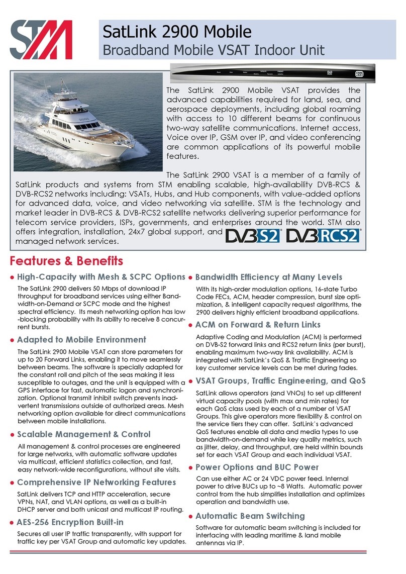
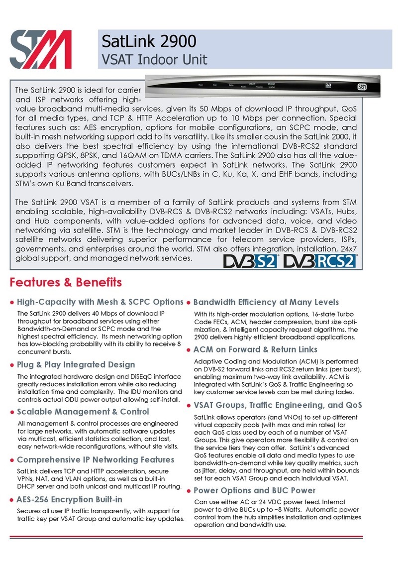
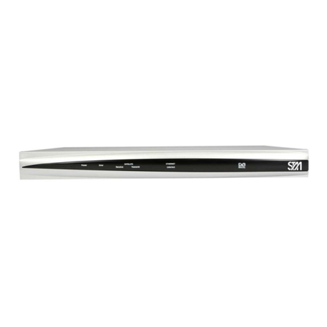
STM SatLink 1910 User manual

SatLink VSAT User Guide
User Guide
Revision PY3– February 4th 2010
Networks without Barriers

SatLink VSAT User Guide
Publication no. 101557 Copyright © 2006-2010 – STM Group, Inc. Page 1 (160)
©
Copyright 2006-2010, STM Group, Inc.
All rights reserved. Reproduction, adaptation or translation without prior written
permission is prohibited, except as allowed under the copyright laws.
®
™
The names of products (hardware and/or software) mentioned herein are regarded to be
the property of their respective companies, regardless of whether or not registration is
indicated.
Notice The information in this publication is subject to change without notice. STM Group, Inc.
makes no warranty of any kind with regard to this material, including, but not limited to,
the implied warranties or merchantability and fitness for particular purposes. Moreover,
STM shall not be held liable for errors that may occur herein or for incidental or
consequential damage in connection with the furnishing, performance, or use of this
material.

SatLink VSAT User Guide
Publication no. 101557 Copyright © 2009 – STM Group, Inc. Page 2 (160)
Table of Contents
1.INTRODUCTION .............................................................................................................................................. 5
1.1ABOUT THIS USER GUIDE.............................................................................................................................6
1.2INITIAL CONFIGURATION..............................................................................................................................6
1.3SYMBOLS......................................................................................................................................................6
2.UNPACKING ..................................................................................................................................................... 7
3.INSTALLATION ............................................................................................................................................... 8
3.1BEFORE INSTALLATION ................................................................................................................................8
3.2SATLINK VSAT IDU FRONT AND REAR PANELS .........................................................................................9
3.3IDU INSTALLATION....................................................................................................................................12
3.4ODU INSTALLATION ..................................................................................................................................13
3.5INTERFACE CONNECTIONS..........................................................................................................................13
4.CONNECTING A PC TO THE SATLINK VSAT........................................................................................ 14
4.1WINDOWS TCP/IP CONFIGURATION ..........................................................................................................14
5.USING THE SATLINK VSAT WEB INTERFACE..................................................................................... 17
6.SATLINK VSAT CONFIGURATION AND LINE-UP USING WEB INTERFACE................................ 18
6.1LOG ON TO THE VSAT WEB INTERFACE ....................................................................................................18
6.2CONFIGURING VSAT PARAMETERS REQUIRED TO LOGON TO THE HUB .....................................................18
6.3LINE-UP USING WEB INTERFACE...............................................................................................................23
6.4TEST OF CONNECTION TO HUB...................................................................................................................26
6.5PREPARE THE STM SATLINK VSAT FOR NORMAL OPERATION.................................................................29
7.STATUS MONITORING USING SATLINK WEB INTERFACE ............................................................. 31
7.1SATELLITE INTERFACE STATUS ..................................................................................................................31
7.2STATISTICS.................................................................................................................................................32
7.3DEVICE STATUS..........................................................................................................................................33
7.4DHCP SERVER STATUS..............................................................................................................................34
8.USING THE COMMAND LINE INTERFACE OF THE SATLINK VSAT ............................................. 36
8.1CLI USER ACCESS RIGHTS.........................................................................................................................36
8.2ONLINE HELP .............................................................................................................................................36
8.3LOGGING OF EVENTS..................................................................................................................................37
8.4CLI COMMAND SUMMARY.........................................................................................................................38
9.SATLINK VSAT CONFIGURATION AND LINE-UP USING COMMAND LINE INTERFACE ........ 41
9.1POWER ON AND LOG ON............................................................................................................................41
9.2INITIAL CONFIGURATION OF PARAMETERS.................................................................................................42
9.3LINE-UP......................................................................................................................................................52
9.4TEST OF CONNECTION TO THE HUB.............................................................................................................56
9.5PREPARE THE STM SATLINK VSAT FOR NORMAL OPERATION.................................................................58
10.NETWORK ADDRESS TRANSLATION (NAT)..................................................................................... 59
11.QUALITY OF SERVICE............................................................................................................................ 63
11.1CONFIGURING QOSFOR THE RETURN LINK................................................................................................64
11.2CONFIGURING THE VSAT FOR VOIP..........................................................................................................66
11.3CONFIGURING THE VSAT FOR VIDEO (VIC) ..............................................................................................67
11.4DSCP AND DIFFSERV.................................................................................................................................67
12.BANDWIDTH ON DEMAND .................................................................................................................... 69
13.TRAFFIC INITIATED LOGON................................................................................................................ 71

SatLink VSAT User Guide
Publication no. 101557 Copyright © 2009 – STM Group, Inc. Page 3 (160)
14.HEADER COMPRESSION........................................................................................................................ 72
14.1ENABLING HEADER COMPRESSION.............................................................................................................72
14.2DISABLE HEADER COMPRESSION ...............................................................................................................73
15.ROUTING OF MULTICAST TRAFFIC .................................................................................................. 74
16.UPDATING THE STM SATLINK VSAT SW.......................................................................................... 75
16.1AUTOMATIC SOFTWARE UPDATE ...............................................................................................................75
16.2MANUAL SOFTWARE UPDATE ....................................................................................................................76
16.3RESTORING THE BACKUP SOFTWARE .........................................................................................................77
17.STM SATLINK AND DVB-S2.................................................................................................................... 78
17.1DVB-S2 MODULATION ..............................................................................................................................78
17.2DVB-S2 CODING .......................................................................................................................................78
17.3DVB-S2 CODING AND MODULATION CONTROL MODES............................................................................80
17.4DVB-S2 CONFIGURATION FOR 1910 IDUS WITH THE SATLINK 100 PLUG-IN CARD...................................81
18.SOFTWARE OPTIONS.............................................................................................................................. 83
18.1GENERIC ROUTING ENCAPSULATION (GRE) AND IP TUNNELLING.............................................................84
18.2TCP PERFORMANCE ENHANCING PROXY (PEP).........................................................................................86
18.3HTTP ACCELERATOR (HTTPA) ................................................................................................................87
18.4FOUR QOSCLASSES ...................................................................................................................................90
18.5RETURN LINK ACCESS CONTROL (RAC)....................................................................................................90
18.6VLAN EXTENSION (802.1Q)......................................................................................................................91
18.7ETHERNET USER PRIORITY (802.1P/D).......................................................................................................93
18.8DVB-S2 16-APSK.....................................................................................................................................94
19.EXTENSIONS FOR MOBILE VSAT........................................................................................................ 95
19.1TRANSMIT INHIBIT FUNCTION ....................................................................................................................95
19.2GPS INTERFACE .........................................................................................................................................96
19.3OPTIMISING THE MOBILE VSAT FOR RECOVERING CONTACT WITH NETWORK AFTER BLOCKINGS..............97
20.MESH VSATS.............................................................................................................................................. 99
21.DEFINITIONS, ACRONYMS AND ABBREVIATIONS...................................................................... 104
22.REFERENCES........................................................................................................................................... 106
APPENDIX A.ACCESSING THE COMMAND LINE INTERFACE VIA SERIAL CONSOLE PORT 107
APPENDIX B.TFTP SERVER......................................................................................................................... 110
APPENDIX C.TELNET CLIENT.................................................................................................................... 111
APPENDIX D.TESTING THE CONNECTION TO THE VSAT................................................................. 112
APPENDIX E.MANAGEMENT VIA SNMP ................................................................................................. 120
APPENDIX F.ODU INSTALLATION............................................................................................................ 128
APPENDIX G.SATLINK 403X. INTERFACING VSAT RX/TX ANTENNAS .......................................... 134
APPENDIX H.MANUAL CONFIGURATION OF PARAMETERS NORMALLY CONFIGURED
AUTOMATICALLY FROM THE HUB .............................................................................................................. 137
APPENDIX I.IDU POWER CALIBRATION WITH BUCS OTHER THAN SATLINK 403X............... 141
APPENDIX J.THE BOOT SW........................................................................................................................ 144

SatLink VSAT User Guide
Publication no. 101557 Copyright © 2009 – STM Group, Inc. Page 4 (160)
APPENDIX K.TROUBLESHOOTING ........................................................................................................... 145
APPENDIX L.COMPLIANCE ........................................................................................................................ 156
APPENDIX M.STANDARDIZATION OF TIMING COMPENSATION................................................ 157
APPENDIX N.RECEIVER AND TRANSMITTER AUTO START ............................................................ 158
APPENDIX O.ACCESSING THE FORWARD LINK SIGNALLING ........................................................ 159

SatLink VSAT User Guide
Publication no. 101557 Copyright © 2009 – STM Group, Inc. Page 5 (160)
1. Introduction
The STM SatLink 1000, 1910, and 2000 are the indoor units (IDUs) of the STM SatLink VSAT family of
DVB-RCS VSATs. They perform several functions: they are satellite modems (at Layer 1); they handle
data link layer processing (at Layer 2) for both satellite and LAN communications; and they act as IP
routers and DHCP servers (at Layer 3). All SatLink IDUs provide an Ethernet 10/100 LAN interface for
one or more PCs to engage in two-way communication via a SatLink (or any DVB-RCS compliant)
satellite network.
Figure 1: STM SatLink 1000, 1910, and 2000 Indoor Units (IDUs)
Figure 2: STM SatLink
Outdoor Unit (ODU)

SatLink VSAT User Guide
Publication no. 101557 Copyright © 2009 – STM Group, Inc. Page 6 (160)
1.1 About this User Guide
This User Guide covers the installation and operation of the STM SatLink 1000/1910/2000, commonly
also referred to as the indoor unit (IDU) of the DVB-RCS VSAT, together with the accompanying
outdoor unit (ODU) equipment. It is intended for DVB professionals, such as service providers and
installers. Therefore, it does not contain information for non-professional users, such as given in the user
manuals of consumer electronic products.
The information given pertains to the following STM software (SW) and hardware (HW) versions and
releases:
SatLink IDU Software
•STM SatLink Boot loader, P/N 101225, SW build 1.8.0.2 and later
•STM SatLink Boot loader, P/N 106267, version 9.0.0 and later
•STM SatLink Boot loader, P/N 120044 , Revision 14.0.0 and later
•STM SatLink DVB-RCS VSAT Software, P/N 101224, version 13.0.1 and later
•STM SatLink DVB-RCS VSAT Software, P/N 120208, version 14.0.0 and later
SatLink VSAT IDU Hardware models
•STM SatLink 100 DVB-S2 Plug-in card for SatLink 1910, P/N 107261
•STM SatLink 1000, P/N 103346
•STM SatLink 1910, P/N 103798
•STM SatLink 2000, P/N 120033
Ku-band Equipment
Transceivers
•STM SatLink 4033, P/N 104804
•STM SatLink 4035, P/N 106546
1.2 Initial Configuration
The STM SatLink VSAT IDU must be configured before it can communicate via the satellite to and from
the network Hub. The parameters to be configured are explained in section 6.2.
The configuration of the VSAT IDU can be carried out using the configuration tools:
•Web-interface (basic configuration only)
•Command Line Interface (CLI)
-Via RS232/Terminal emulator (e.g. HyperTerminal)
-Telnet
•SNMP
The SatLink VSAT Web-interface is used as the main interface for initial configuration of the VSAT
parameters and is presented in section 6. The status monitoring of the VSAT using Web interface is
presented in section 7. Configuration via CLI is presented in section 9 and management via SNMP is
presented in Appendix E. The Web interface can be used for most common configuration tasks, while
advanced configuration is only available via SNMP and CLI.
1.3 Symbols
NOTE
Additional information that the reader should pay special attention to.
WARNING
System malfunction may occur if the warning-information is violated.

SatLink VSAT User Guide
Publication no. 101557 Copyright © 2009 – STM Group, Inc. Page 7 (160)
2. Unpacking
Check that the following items are in the box received, and then unpack.
•SatLink 1000, 1910, or 2000
•Stand for vertical placement (SatLink 1000 only)
•AC adapter (SatLink 1000/2000 only )
•Power cord
•Brackets for 19” rack mounting (SatLink 1910 only)

SatLink VSAT User Guide
Publication no. 101557 Copyright © 2009 – STM Group, Inc. Page 8 (160)
3. Installation
3.1 Before Installation
3.1.1 Safety
Follow these guidelines to ensure general safety:
•Always comply with national and local electrical codes.
•Keep the installation area clear and dust free during and after installation.
•Keep tools and all components away from walk areas.
•Do not wear loose clothing, jewellery (including rings and chains), or other items that might get
caught on the IDU, the ODU or the interconnecting cables.
•Do not work on the system or connect or disconnect cables during lightning storms.
Follow these guidelines when working with electrical equipment:
•Disconnect all power and external cables before installing or removing a SatLink VSAT IDU.
•Do not work alone when potentially hazardous conditions exist.
•Never assume that power has been disconnected from a circuit; always check.
•Do not act in any way that creates a potential hazard to people or makes the equipment unsafe.
•Never install equipment that appears damaged.
•Carefully examine your work area for possible hazards such as moist floors, unearthed power
extension cables and missing protective earths.
Should an electrical accident occur:
•Be cautious – do not become a victim yourself.
•Turn off electrical power to the system.
•If possible, send another person to get medical aid. Otherwise, assess the condition of the victim and
then call for help.
•Determine if the victim needs artificial respiration or external cardiac compressions; then take
appropriate action.
3.1.2 Site requirements
The STM SatLink VSAT IDU shall be connected to 110/240 VAC, 50-60Hz power.

SatLink VSAT User Guide
Publication no. 101557 Copyright © 2009 – STM Group, Inc. Page 9 (160)
3.2 SatLink VSAT IDU Front and Rear Panels
3.2.1 SatLink 2000 Front and Rear panel
Figure 3 : SatLink 2000 Front Panel
LED Colour, indicates
Power Yellow, lights steadily when connected to the power supply and unit is powered. Flashes
when loading software.
Error Red, lights steadily when an error event occurs and during reboot.
Satellite Receive Blue, flashes when the receiver is searching for the carrier.
Lights steadily when receiver is on and functioning properly.
Flashes when IP packets are received from the Satellite Interface (the Hub).
Transmit
Blue, flashes rapidly when a continuous wave (CW) is transmitted.
Lights steadily when the VSAT is logged on to the DVB-RCS Hub.
Flashes when IP packets are transmitted to the Satellite Interface (the Hub).
Ethernet Link/Act Blue, lights steadily when Ethernet connectivity is OK.
Flashes slowly when Ethernet packets are transferred via the Ethernet interface.
Status For future use
Table 1: SatLink 2000 Front Panel LEDs
Figure 4 : SatLink 2000 Rear Panel
Item Description
Power Connector Connector for cable to the 24 V DC power transformer (external power supply provided
with STM SatLink 2000 VSAT)
Ethernet
Connector RJ45 connector for IP traffic to connect to a PC, Ethernet switch, IP router etc. 10BASE-T
or 100BASE-T modes is detected automatically.
COM1 Connector Nine pin connector for connecting CLI interface to a computer’s DB-9 serial interface.
RX coaxial jack Coaxial 75 ΩF-type jack for the cable to the LNB.
TX coaxial jack Coaxial 75 ΩF-type jack for the cable to the BUC.
Table 2: SatLink 2000 Rear Panel LEDs

SatLink VSAT User Guide
Publication no. 101557 Copyright © 2009 – STM Group, Inc. Page 10 (160)
3.2.2 SatLink 1000 Front and Rear panel
Figure 5: SatLink 1000 Front panel
LED Colour, indicates
Power Blue, lights steadily when power switch is on and unit is powered. Flashes when loading
software.
Error Red, lights steadily when an error event occurs and during reboot.
Satellite Receive Blue, flashes when the receiver is searching for the carrier.
Lights steadily when receiver is on and functioning properly.
Flashes when IP packets are received from the Satellite Interface (the Hub).
Transmit
Blue, flashes rapidly when a continuous wave (CW) is transmitted.
Lights steadily when the VSAT is logged on to the DVB-RCS Hub.
Flashes when IP packets are transmitted to the Satellite Interface (the Hub).
Ethernet Link/Act Blue, lights steadily when Ethernet connectivity is OK.
Flashes slowly when Ethernet packets are transferred via the Ethernet interface.
Table3: SatLink 1000 Front Panel LEDs
Figure 6: SatLink 1000 Rear Panel
Item Description
On/off switch Power on (1) or off (0).
Power Connector Connector for cable to the 24 V DC power transformer (external power supply provided
with STM SatLink 1000 VSAT)
Ethernet
Connector RJ45 connector for IP traffic to connect to a PC, Ethernet switch, IP router etc. 10BASE-T
or 100BASE-T modes is detected automatically.
COM1 Connector Nine pin connector for connecting CLI interface to a computer’s DB-9 serial interface.
RX coaxial jack Coaxial 75 ΩF-type jack for the cable to the LNB.
TX coaxial jack Coaxial 75 ΩF-type jack for the cable to the BUC.
Table 2: SatLink 1000 Rear Panel Description
3.2.3 SatLink 1910 Front and Rear Panel

SatLink VSAT User Guide
Publication no. 101557 Copyright © 2009 – STM Group, Inc. Page 11 (160)
Figure 7: SatLink 1910 Front Panel
LED Colour, indicates
Power Blue, lights steadily when power switch is on and unit is powered. Flashes when
loading software.
Error Red, lights steadily when an error event occurs and during reboot.
Satellite Receive Blue, flashes when the receiver is searching for the carrier.
Lights steadily when receiver is on and functioning properly.
Flashes when IP packets are received from the Satellite Interface (the Hub).
Transmit
Blue, flashes rapidly when a continuous wave (CW) is transmitted.
Lights steadily when the VSAT is logged on to the DVB-RCS Hub.
Flashes when IP packets are transmitted to the Satellite Interface (the Hub).
Ethernet Link/Act Blue, lights steadily when Ethernet connectivity is OK.
Flashes slowly when Ethernet packets are transferred via the Ethernet interface.
Table 1: SatLink 1910 Front Panel LEDs
Figure 8: SatLink 1910 Rear Panel
Item Description
On/Off switch Power on (1) or off (0).
Power Connector Standard recessed plug for Power cord.
Ethernet
Connector RJ45 connector for IP traffic to connect to a PC, Ethernet switch, IP router etc.
10BASE-T or 100BASE-T mode is detected automatically.
COM1
Connector Nine pin connector for connecting CLI interface to a computer’s DB-9 serial
interface.
Cover for Accessory Card Not used.
RX coaxial jack Coaxial 75 ΩF-type jack for the cable to the LNB.
TX coaxial jack Coaxial 75 ΩF-type jack for the cable to the BUC.
Table 2: Description of SatLink 1910 Rear Panel

SatLink VSAT User Guide
Publication no. 101557 Copyright © 2009 – STM Group, Inc. Page 12 (160)
3.3 IDU Installation
3.3.1 On Desktop or Shelf
Place the STM SatLink VSAT IDU on a flat, stable surface, such as a desktop or shelf, close to the PC or
network device to which it will be connected. Keep its top, bottom and all sides unobstructed to ensure
free airflow. Rubber feet on the bottom provide adequate clearance. Ensure that there is at least 10 cm
clearance at the back to allow room for cable connections.
3.3.2 In Rack
The rack or cabinet should be properly secured to prevent tipping. Equipment that is
installed in a rack or cabinet should be mounted as low as possible, with the heaviest units
lower down, and lighter units toward the top.
Precautions:
•Ensure that the power circuits are properly grounded and use the power cord supplied with the
SatLink VSAT IDU to connect it to the power outlet.
•If your installation requires a different power cord than the one supplied, ensure that the cord used is
certified as indicated by the stamped or embossed logo of the electrical safety authority in your
country.
•If the on/off switch on the back panel is difficult to reach when the unit is fitted in the rack, ensure
that the power outlet into which it is plugged can be reached so it may be unplugged if necessary.
•Ensure that the unit does not overload the power circuit, wiring or over-current protection. To
determine the possibility of overloading the supply circuits, add together the ampere ratings of all
devices installed on the same circuit as the STM SatLink VSAT IDU and compare the total with the
rating limit for the circuit. The maximum amperage ratings are usually printed on units near their
power connectors.
•Do not install the STM SatLink VSAT IDU in a location where the operating ambient temperature
may exceed 45°C.
•Ensure that the airflow around the sides and back of the SatLink VSAT IDU is not restricted.
The STM SatLink 1900/1901/1910 can be mounted in any EIA-standard 19-inch telecommunications
rack or cabinet. The STM SatLink 1000 and 2000 need to be placed on a shelf if it is to be placed in a
rack.
Use a Torx screwdriver and attach the mounting brackets to the router with the screws supplied. Hold the
unit securely, brackets attached, and move it vertically until rack holes line up with the bracket notches,
then insert and tighten the four screws holding the brackets to the rack.
Figure 9: Rack Mounting

SatLink VSAT User Guide
Publication no. 101557 Copyright © 2009 – STM Group, Inc. Page 13 (160)
3.4 ODU Installation
Install the ODU as described in Appendix F, reference [1], and the antenna installation manual. When
installing the STM SatLink 403x transceiver, please check Table 9 in Appendix G whether an adapter is
required to interface the antenna feed horn.
3.5 Interface Connections
3.5.1 RX/TX cables between IDU and ODU
The coaxial cables from the ODU are connected to the type F coaxial jacks on the back panel of the STM
SatLink VSAT IDU.
•Connect one coaxial cable from the ODU TX module input to the jack marked TX.
•Connect one coaxial cable from the LNB to the port marked RX on the back panel.
Use only 75 Ωcoaxial cables fitted with type F plugs for the RX and TX cables. Make sure
that the connectors are of a waterproof version such as F-connector RG6 Compression type
from Cablecon (www.cablecon.dk), article no 99909446
Do not connect and disconnect the coaxial cables with power connected to the STM
SatLink VSAT IDU.
Hint
Use different colour marking on the TX and RX coaxial cables to eliminate likelihood of
interchanging the RX and TX coaxial cables.
3.5.2 Ethernet connection to a Local Area Network (LAN)
The STM SatLink VSAT IDU may be connected to a single PC or to a network via the RJ-45 Ethernet
jack on the back panel.
•Plug one end of the Ethernet cable into the RJ-45 jack on the back panel.
•Plug the other end of the Ethernet cable into the RJ-45 jack a Local Area Network (LAN) device such
as an Ethernet hub, switch or router, according to its manufacturer’s instructions.
The STM SatLink will auto-detect if Ethernet HUB or NODE mode is used and will automatically chose
correct mode, hence there is no need to use a cross-over Ethernet cable for direct connections to PCs.
3.5.3 Power connection
The STM SatLink 1910 models have internal power supply and consequently are connected directly to a
110/230 VAC 50/60Hz outlet using a standard 230 VAC power cord.
3.5.4 Power supply
The STM SatLink 1000 and 2000 have an external power supply that is connected to a 110/240 VAC
50/60Hz outlet using a standard power cord.
The STM SatLink 100 and 2000 must only be connected to the external power supply that
is approved by STM, PN 104170 (LEI-S2425D/Adapter Technology, Model No. STD-2425).
Use of another power supply will void warranty.

SatLink VSAT User Guide
Publication no. 101557 Copyright © 2009 – STM Group, Inc. Page 14 (160)
4. Connecting a PC to the SatLink VSAT
After installation as described in Chapter 3 is carried out, the VSAT IDU is ready to be powered on.
4.1 Windows TCP/IP Configuration
Verify that the TCP/IP configuration is correct for PCs connected to the LAN you plan to use for your
SatLink VSAT. Push the start-button in Windows, select the Control Panel and then open Network
Connections. Right-click on the relevant Local Area Connection and select Properties. A new window
showing the Network Connection Properties will pop up. In the General submenu of this window, scroll
down, select Internet Protocol (TCP/IP) and then push the Properties button shown in Figure 10. Then
configure the PC client to obtain the IP address automatically from the VSAT IDU (section 4.1.1) or
configure the PC with a static IP address (section 4.1.2).
Figure 10: Windows XP Menu for Configuring the Client TCP/IP Configuration.

SatLink VSAT User Guide
Publication no. 101557 Copyright © 2009 – STM Group, Inc. Page 15 (160)
4.1.1 Dynamic IP configuration of PCs connected to the VSAT LAN
By default the DHCP server in the SatLink VSAT is enabled. When the SatLink VSAT is powered on, all
PCs connected to the VSAT LAN can automatically retrieve their IP configuration from the DHCP
server. The user should verify that the Windows clients are configured to obtain an IP address and DNS
server address automatically. Figure 11 shows the correct Windows XP configuration when the DHCP
server is enabled in the VSAT.
Figure 11: Windows XP TCP/IP setting when DHCP server is enabled in the VSAT
From an MS-DOS window, the user may type ipconfig /all command to verify that the computer has
received correct configuration parameters from the DHCP server such as IP address, subnet mask, default
Gateway, DNS servers and lease time.
Figure 12: ipconfig /all print out from an MS-DOS window

SatLink VSAT User Guide
Publication no. 101557 Copyright © 2009 – STM Group, Inc. Page 16 (160)
4.1.2 Static IP configuration of PCs connected to the VSAT LAN
When the DHCP server in the SatLink VSAT is disabled, all PCs attached to the VSAT LAN must be
configured with static IP addresses that are within the address range of the VSAT subnet. The IP
configuration parameters to use for PCs connected to the VSAT LAN are supplied from the system
operator or service provider. Configure the IP address, Subnet mask, Default gateway, Preferred DNS
server, and optionally the Alternate DNS server as shown in Figure 13.
Ensure that the actual IP addresses supplied by the system operator/service provider are
configured and not the IP addresses in the example figure.
Figure 13: Windows XP TCP/IP setting when DHCP server is disabled in the VSAT
Example:
A host may have the following configuration; IP address 192.168.0.2, Subnet mask 255.255.255.0 and
default gateway 192.168.0.1, where the IP address of the default gateway should be the IP address of the
VSAT LAN interface.

SatLink VSAT User Guide
Publication no. 101557 Copyright © 2009 – STM Group, Inc. Page 17 (160)
5. Using the SatLink VSAT Web Interface
The SatLink VSAT Web interface supports managing the most common configuration parameters and
viewing the status of the STM SatLink VSAT. The web-browser currently supported is Microsoft Internet
Explorer, but other browsers like e.g. Opera 9.x typically work fine as well. The functions available via
the Web-interface are:
•Configuring the most commonly used satellite interface parameters
•Configuring the most commonly used IP parameters
•Return link line-up procedure
•Viewing status information for the satellite interface
•Viewing traffic statistics
•Viewing device information
•Viewing status of the DHCP server
•Viewing Event log information
Advanced functions such as adding SW licenses, configuring GRE tunnels, downloading software
updates manually, configuring automatic software updates, configuring system information, adding users
and changing password, configuring SNMP access, and adding manual IP routes, etc, are only available
from the CLI via Telnet or the RS-232 port.
To manage the SatLink VSAT via the Web interface, start the web browser and type in the IP address of
the STM SatLink VSAT in the address field as shown in Figure 14. The factory default IP address of the
SatLink VSAT is 192.168.0.1. Use the STM SatLink VSAT’s Satellite Interface (DVB) IP address when
connecting to the VSAT over the satellite link (from the Hub), and the STM SatLink VSAT’s LAN
(Ethernet) IP address when connecting to the VSAT from the local LAN. Then enter the username and
password to logon to the VSAT.
Figure 14: Connecting to the web-interface

SatLink VSAT User Guide
Publication no. 101557 Copyright © 2009 – STM Group, Inc. Page 18 (160)
6. SatLink VSAT Configuration and Line-up Using Web
Interface
Follow all the procedures mentioned below when installing the SatLink VSAT and lining up the ODU
using the Web interface. Please see section 7 for SatLink VSAT status monitoring using Web interface
6.1 Log On to the VSAT Web interface
1) Start the web browser and type in the IP address of the STM SatLink VSAT in the address field.
2) Loginwith username install and factory default password dvbrcs. Click the OK button.
User name: install
Password : dvbrcs
Figure 15 : Logon Page
6.2 Configuring VSAT Parameters required to logon to the Hub
The SatLink VSAT Web interface is used to configure a number of parameters before the VSAT can
acquire the forward link and communicate with the Hub via the satellite connection. A default
configuration specifying most of these parameters is pre-loaded on each STM SatLink VSAT, either in
the factory or by the service provider before installation. The following configuration parameters are
typically to be configured using the VSAT Web interface:
-DVB-S2 Reception parameters
-VSAT GPS Position
Other parameters are typically configured automatically from the Hub when the VSAT logs on for the
first time . When other ODUs than the SatLink 403x transceiver is used or if e.g. the Hub operator does

SatLink VSAT User Guide
Publication no. 101557 Copyright © 2009 – STM Group, Inc. Page 19 (160)
not use automatic VSAT configuration then additional VSAT parameters ight have to be configured
during installation.
6.2.1 Receiver Parameter Configuration
The STM SatLink VSAT is normally pre-configured to be used together with the STM SatLink 403x
transreceiver. But, it is possible to configure the STM SatLink VSAT to operate together with other
transreceivers than SatLink 403x. The list of LNBs that can be used with the STM SatLink VSAT are
listed in Table 5
1) Click on the Satellite option in the SatLink VSAT home page.
Figure 16 : Configuring Receiver Parameters
2) Configure the Receiver parameters as shown in the following table.
Parameter Description
Auto Start •ON
•Off
Specific for the receiver. When set to "ON" the VSAT will automatically acquire the
forward link. It is recommended to always set this to ON for normal operation. Please
always restart the VSAT after saving configuration when having set auto start to ON.
LNB Type Specifies the LNB type with which the VSAT is configured.
Index Table index [0 – 9]. The SatLink VSAT can store up to 10 forward link entries and the
table index is used to identify a single entry.
Priority Forward link search order [0 – 1]. Search is started for priority 0 first and ends with
priority 1.
Symbol Rate (Msps) The forward link symbol rate in Msps.
Frequency (Ghz) Forward link frequency [kHz].
Mode Enter the valid modes :
•DVB-S
•DVB-S2
PopId Population ID to use for forward link acquisition. The STM SatLink VSAT will select
which group in the DVB-RCS system it belongs to based on the configured population
This manual suits for next models
2
Table of contents
Other STM Modem manuals
