Micro-Aide LPM-33 User manual

685 Arrow Grand Circle Covina, CA 91722
LPM-33
LOW POWER MODEM
USER MANUAL
MICRO-AIDE
HIGHWAY PRODUCTS
LOW POWER MODEMS
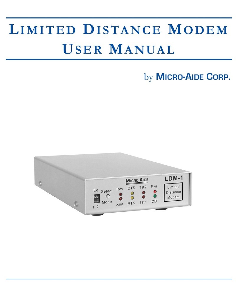
LIMITED DISTANCE MODEMS
LIGHT OUT DETECTORS
LOCAL CONTROL UNITS
LOAD SWITCHES
CUSTOM ENGINEERING

2
Description
This document is intended to provide a detailed
description of the use and operation of the
MICRO-AIDE LPM-33 Low Power Modem.
The LPM-33 is specifically designed for use in
highway applications requiring remote access via
standard telephone lines. It will operate in very
severe temperature conditions, including those
typically associated with roadside facilities. It can be
powered by any source in the range from 5 to
36 Vdc. More importantly, it features a low power
standby mode that allows it to be battery powered. A
solar panel charged battery provides a fully
satisfactory method of powering the LPM-33.
Several timers are employed by the LPM-33. The
timers are used to reduce net power consumption in
typical applications. Sixty seconds after the
termination of ringing voltage or 120 seconds after
the cessation of DTE data the LPM-33 will
automatically revert to its low power standby mode.
Standby mode will also be invoked 10 seconds after
the loss of carrier is detected. The mode control
sequence employed by the LPM-33 is fully depicted
in Figure 1.
Baud rates up to 33,600 are supported by the
LPM-33. Its high speed makes the LPM-33 ideally
suited to weigh-in-motion applications where large
amounts of data are typically transferred. CCITT and
Bell standard error correction and data compression
algorithms are also supported. The LPM-33 will
operate in auto-answer and originate modes.
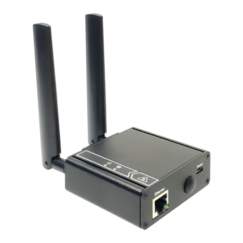
The LPM-33 is housed in a rugged aluminum case.
Six front panel mounted LEDs indicate the status of
the modem at all times. A standard DB-25 connector
allows the LPM-33 to be easily connected to a
variety of roadside data devices.
Figure 1 provides a flow diagram of the modem’s
standby and active mode control sequences. Figure 2
provides a three-sided, fully dimensioned view of the
LPM-33. The last page of this document lists
detailed specifications.
Installation
In its standard configuration the LPM-33 is placed on
a shelf or flat horizontal surface. It is equipped with
four non-slip rubber feet. Shelf mounting brackets
that allow the LPM-33 to be secured to a shelf or
backboard are available from MICRO-AIDE upon
request. The mounting brackets are attached to the
bottom of the LPM-33 by removing the four rubber
feet. The vacated screw holes are used to secure the
brackets.
A standard 25-pin, RS-232 cable can be used to
connect the LPM-33 to the DTE device. The
LPM-33 is equipped with a female connector
configured for DCE operation. The list of
specifications includes each of the RS-232 signals
provided by the modem.
The telephone line is attached to the LPM-33 via a
standard RJ-11 connector. Dual female jacks are
available at the LPM-33 so that a utility phone can be
used while the modem is inactive.
A 6 ft. long power cable is shipped with every
LPM-33. The cable is terminated with a standard
3.5 mm plug. The plug mates with the power jack
located on the rear panel of the LPM-33. The red
wire of the cable attaches to the center pin of the jack
and must be connected to the positive terminal of the
LPM-33
LOW POWER MODEM
USER MANUAL
Commercially available modems are generally not suitable for use in roadside applications.
The LPM-33, however, operates over a temperature range extending from –40°C to +72°C.
I
ts low power design allows it to be powered by typical solar panel systems.

3
power source. The black wire must be connected to
the negative terminal of the power source.
Alternatively, the LPM-33 can be powered by a
nominal 12 Vac source. A Stancor STA-4112A wall
mount transformer can be used for this purpose. It
connects directly to any 120 Vac outlet. The
transformer has a rated output of 12 Vac at 500 mA.
Its output cable is terminated with a 3.5 mm plug.
Note - Contact MICRO-AIDE if the Stancor wall
mount transformer is required.
Setup and Operation
Except as noted below, after power is applied to the
LPM-33 the green “STBY” LED should start to flash
immediately. This indicates the modem is in low
power standby mode. The LED should turn off when
the modem receives DTE data or auto-answers an
incoming call.
The standby mode of the LPM-33 can be disabled.
This option may be of benefit in applications where
the modem is not being powered by a solar panel.
Disabling the standby mode of the LPM-33 forces
the modem into continuous active mode.
To disable standby mode remove the cover of the
LPM-33. Four screws located along the sides of the
modem secure the cover in place. Locate the jumper
labeled “JP1” on the printed circuit board. Install the
shorting jumper so that it bridges both pins of JP1.
Reattach the cover. The standby LED will remain
off with power applied to the modem.
Reminder - For low power standby operation
remove the JP1 jumper. To disable standby
operation install the JP1 jumper.
The user may be required to install an operational
profile into the LPM-33. Modem profiles are
determined by the operating aspects of the DTE
attached to the LPM-33 and the required application.
The LPM-33 conforms to the industry standard set of
AT commands. However, several modem
characteristics (e.g., error correction control) are not
uniformly coded by modem chip manufacturers. A
complete list of AT commands used by the LPM-33
is available.
Note - Contact MICRO-AIDE if a complete
description of the AT command set used by the
LPM-33 is needed.
Install and save the required profile by connecting
the communications port of a PC directly to the
RS-232 connector of the LPM-33. A
communications program (e.g., HyperTerminal®)
can be used to communicate with the LPM-33.
Note - Unless otherwise requested by the user, both
profiles used by the LPM-33 are set to the default
values established by the modem chip manufacturer.
After the correct profile is programmed into the
LPM-33 the modem is ready for use in the intended
application.
Maintenance and
Trouble-shooting
The LPM-33 is designed to be completely
maintenance free. It contains no consumable
materials or serviceable components. If the unit fails
to power-up (as indicated by the green standby LED
not flashing) the unit should be returned to
MICRO-AIDE for repair.
The operation of the LPM-33 can be easily tested.
Any PC equipped with a modem and a
communications program (e.g., HyperTerminal®)
can be used to access the LPM-33. A check of the
modem’s ability to answer, connect and communicate
can be performed very effectively. Remote tests of
the LPM-33 can be made by MICRO-AIDE
technicians at the request of the user.
MICRO-AIDE provides a limited three-year
warranty of the LPM-33. Telephone numbers and a
shipping address are listed below.
MICRO-AIDE CORPORATION
685 Arrow Grand Circle
Covina, CA 91722
Tel: 626-915-5502
Fax: 626-331-9484

4
Y
N
Y
N
Y
N
Y
N
Y
N
Standby
Mode
Ring in
?
DTE data
?
T. O . = 1 2 0 s e c .
T. O . = 6 0 s e c .
Active
Mode
Decr. T.O
1 sec.
T. O . = 0 s e c .
?
Carrier on
?
Call in
progress
Carrier on
?
T.O.=10 sec.
T.O. refers to
Time Out value
Figure 1 - Mode control flow diagram

5
Figure 2 – Three-sided view
8.5"
5.3"
LPM-33
33.6K
LOW POWER
MODEM
STBY SD CD
RI RD OH
MA
ICRO- IDE
1.9"
RS-232
TO DTE MADE IN USA
PWR IN PHONE
LINE
5-36 VDC
12 VAC

6
Physical
Size
Length: 8.6"
Width: 5.3"
Height: 1.9"
Weight
20 oz.
Environmental
Storage
Temperature: -40°C to 85°C
Humidity: 0 to 95%, non-
condensing
Operating
Temperature: -40°C to 72°C
Humidity: 0 to 95%, non-
condensing
Mounting
Standard: shelf or desk top
Optional: mounting brackets
available upon request
Construction
Housing
Fully enclosed, anodized
aluminum
Electrical
Components mounted on
internal PCB
Power
Voltage
5.0 to 36 Vdc, 10 to 15 Vac
Consumption
Standby: .5 mA at 12 Vdc
(maximum)
Active: 85 mA at 12 Vdc
(typical)
Operation
Speed
Baud rates to 33,600
Type
Auto-answer and originate
Modem Standards
CCITT
V.34, V.32 bis, V.32, V.22 bis,
V.22, V.21
Bell
103, 212A
Data Compression
MNP 5 and V.42 bis
Error Correction
MNP 2-4 and LAP-M
Control Commands
Hayes AT command set;
additional AT commands for
data compression, error
correction, cellular operation
Profiles
2, set at factory, user definable,
stored in non-volatile E2PROM
Mode Control
Standby
Awaits ringing or DTE data
Standby to Active
Within 6 seconds of ringing or
200 msec of DTE data
Answer
After transition to active mode
answers call in accordance with
S0 register setting
Disconnect
Loss of carrier, DTR drop or on-
hook command
Active to Standby
Active Connection: 10 seconds
after loss of carrier
No Connection: 60 seconds
after last ring or 120 seconds
after last DTE data
DCE - DTE Interface
Type: RS-232
Speed: auto-detects with AT
command, up to 115,200 Baud
Signaling: N-8-1
Controls
Internal
Jumper JP1: disables standby
operation if jumper is on
External
None
LED Indicators
Standby: green
Ringing: red
Send Data: red
Receive Data: red
Carrier Detect: red
Off Hook: red
Connectors
Power
Standard 3.5 mm jack, center
positive
To DTE
DB-25 female, configured as
DCE
Pin 1: Protective Ground
Pin 2: Send Data
Pin 3: Receive Data
Pin 4: Request to Send
Pin 5: Clear to Send
Pin 6: Data Set Ready
Pin 7: Signal Ground
Pin 8: Carrier Detect
Pin 20: Data Terminal Ready
Pin 22: Ring In
Telephone Line
Dual female RJ-11, wired in
parallel
Line Protection
Internal gas tube arrestor,
230 Vdc, tip and ring to ground
Note: a telco approved external
suppressor should be used for
added protection
Regulatory
Designed to meet applicable
FCC standards
LPM-33
LOW POWER MODEM
SPECIFICATIONS
Table of contents
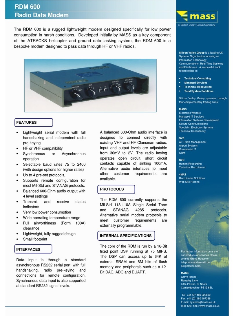
Other Micro-Aide Modem manuals
