MICRO-AIR SCA Series User manual

Installation and Operation Manual
Important:
This manual contains specific cautionary statements relative to worker safety. Read this manual thoroughly and follow
as directed. It is impossible to list all the hazards of dust control equipment. All persons involved with the equipment or
systems should be instructed how to operate in a safe manner.
MODEL SCA

MODEL SCA SPECIFICATIONS
INPUT VOLTAGE:
120V 60Hz 1 Phase
230V 60Hz 1 Phase
208-230V / 460V 60Hz 3 Phase
EXHAUSTER BLOWER/MOTOR:
TEFC 1 HP, 1 Phase - 12.0Amps @ 120 VAC
TEFC 1 HP, 3 Phase - 3.2Amps @ 230 VAC
TEFC 1 HP, 3 Phase - 1.6Amps @ 460 VAC
TEFC 3 HP, 3 Phase - 8.0Amps @ 230 VAC
TEFC 3 HP, 3 Phase - 4.0Amps @ 460 VAC
AIR FLOW:
SCA400: 4” Dia. Arms - 1275 CFM, 1HP exhauster
SCA600: 6” Dia. Arms - 1825 CFM, 1HP exhauster
SCA600: 6” Dia. Arms - 2000 CFM, 3HP exhauster
SCA800: 8” Dia. Arms - 2000 CFM, 3HP exhauster
ARM LENGTH:
5’- 4” Diameter
7’- 4”, 6” & 8” Diameters
9’- 6” & 8” Diameters
12’- 6” & 8” Diameters
HOOD LAMP:
12 V. Halogen @ 4 Amps (standard)
WEIGHT:
4” Dia. - 5’= 21 lbs.
4” Dia. - 7’= 23 lbs.
6” Dia. - 7’= 48 lbs.
6” Dia. - 9’= 51 lbs.
6” Dia. - 12’= 59 lbs.
8” Dia. - 7’= 59 lbs.
8” Dia. - 9’= 64 lbs.
8” Dia. - 12’= 67 lbs.
1 HP Motor/Blower Assembly = 45 lbs.
3 HP Motor/Blower Assembly = 70 lbs.
RANGE OF MOTION:
See Figure 1. Factory set for “A” at 10 Deg. Moving the
adjustment collar closer to the socket end of the pipe will
reduce the amount of upward motion.
Caution:
All electrical work must be done by a
qualified electrician according to local, state
and national codes.
Typical installations require that the
blower or gusset assembly be mounted to
a wall. Be sure that the wall is structurally
sufficient to support the arm assembly
being installed.
Arm Size “A” “B”
SCA405 40 Deg. 90 Deg.
SCA407 50 Deg. 90 Deg.
SCA607 38 Deg. 90 Deg.
SCA609 60 Deg. 90 Deg.
SCA612 60 Deg. 90 Deg.
SCA807 45 Deg. 90 Deg.
SCA809 70 Deg. 90 Deg.
SCA 812 68 Deg. 60 Deg.
PRE-OPERATING INSTRUCTIONS:
1. Open cardboard carton(s) and remove unit. Remove
packaging supports from arm assembly. Be careful not
to dent the steel tubes on the arm during unpacking.
2. Inspect the unit for damage that may have been caused
during shipping. Immediately report any such damage
to the shipping carrier.
3. Examine the unpacked unit and compare it to the
parts list description to verify that all components are
received. If a component is missing from the assembly,
contact your Micro Air representative.
Fig. 1
MICRO AIR®SCA
CLEAN AIR SYSTEMS
!
2
!

INSTALLATION:
NOTE: Due to the numerous system combinations
available, some of the following installation steps
may not be applicable. Follow steps that directly
address the specific system being installed.
1. Determine the location where the arm assembly will be
installed (typically at a 10’height).
2. Drill holes into wall or support that align with the
gusset or blower mount assembly. Attach the assembly
to the wall using hardware provided (Fig. 2).
3. Attach the arm sub-assembly to the motor/blower or
gusset assembly as shown (Fig. 3). It is recommended
that two (2) people perform this step; one to support
the arm assembly, while the other attaches hardware
to clamp the arm assembly onto the motor/blower or
gusset assembly.
4. Secure the control cable to the arm base using hose
clamp. Allow enough slack so arm can move freely
(Fig. 4).
SCA MICRO AIR®
CLEAN AIR SYSTEMS
3/8 Hex Bolt X 1
3/8 Plain Washer X 2
3/8 Lock Washer X 1
3/8 Hex Nut X 1
3
Fig. 2
Fig. 4
Fig. 3
Hose Clamp
1/4” Washer
1/4” Washer
1/4” Washer
1/4-20 Nylock Nut
1/4-20 Hex Bolt
1/4” Lock Washer
1/4-20 Hex Bolt
1/4” Lock Washer

4
MICRO AIR®SCA
CLEAN AIR SYSTEMS
ELECTRICAL INSTALLATION:
Caution:
Installation can cause exposure to live
parts. Disconnect electrical power before
proceeding with installation.
1. An electrical control box is included to house
appropriate control transformers, relays, and motor
starters. Locate the electrical control box and mount
to wall or support, anywhere within reach of the arm
control cable connector.
2. Connect the motor/blower power cord to the electrical
control box (Fig. 5). The power cord is pre-wired to
the motor blower.
3. Confirm that the motor wiring matches the supply
voltage.
4. Confirm that the blower impeller wheel is rotating in
the correct direction when energized (Fig. 6).
5. Connect the arm control cable to the electrical control
box (Fig. 5). The arm control cable is pre-wired for
turning the lamp on and/or the motor/blower on.
6. Connect input power to the electrical box at the labeled
terminal strip. Refer to specific wiring diagrams
and Fig. 5 for details. Be sure to ground input to the
electrical control box per local electrical codes.
OPERATION:
1. Upon completion of installation, the SCA should
appear similar to the system shown in Fig. 7.
2. Grasp the hood handle and lift the lower arm section
up and down. If the middle joint seems to tight, loosen
the two nylock hex nuts that hold the joint together
in 1/4-1/2 turn increments. If the arm has trouble
maintaining a position, tighten the nuts.
3. The hood joint section can be manipulated up and
down as well as right and left. If the joints are too
loose or too tight, simply adjust the nylock hex nuts as
needed.
4. To operate the blower, depress the fan switch located
on the remote switch control box to ON. The blower
motor will activate via a motor relay located inside the
electrical control box.
5. Activate the lamp located inside the hood by depressing
the lamp switch located on the remote switch control
box.
6. The damper lever near the hood can be rotated 90
degrees to adjust the inlet air velocity.
Input Power
120V 1-Ph.
208-460V 3-Ph.
Motor/Blower
Cord Set
Arm Control
Cable
Fig. 5
Fig. 6
!
Fig. 7

5
SCA MICRO AIR®
CLEAN AIR SYSTEMS
TROUBLE SHOOTING CHART
CAUTION: BEFORE DISASSEMBLING THE UNIT OR DOING ANY INSPECTING OF THE PARTS, MAKE
CERTAIN THAT THE POWER HAS BEEN CUT OFF AND THE BLOWER HAS COME TO A COMPLETE STOP.
PROBLEM POSSIBLE CAUSE REMEDY
Blower fails to
start No incoming power
Blown breaker or fuse
Primary voltage to motor contactor is below 10%
tolerance
Burned out motor
Check line voltage
Replace fuse or throw breaker
Take steps to increase voltage to primary
Replace motor
Unit runs slowly or
inadequate capture
velocity
Wired for wrong voltage or improper rotation
Internal obstruction
Check input voltage
Check wiring diagram
Switch L1 & L2 (3-phase only)
Check if damper is open
Check inlet for blockage
Check hoses for proper connection
Check hoses for holes
Vibration Loose motor mount bolts
Foreign objects in blower
Tighten bolts
Remove debris from blower
Stronger resistance
during rotation of
the arm
Lack of grease in the rotating socket Grease the rotating socket
Arm will not stay
where it is placed The joints are loose Tighten the joints
GENERAL MAINTENANCE:
Daily
• Clean out any debris from the inner surface of the hood.
• Adjust any loose joints.
Once per month
• Grease the rotating socket with bearing grease listed to not react with Aluminum.
Once per 3 months
• Inspect the condition of the flexible hose for any opening that will allow air to flow through.
• Check the blower motor for bearing noise and impeller wheel for debris and dirt. No lubrication is required for the
motor since it is a totally enclosed, fan cooled type, with permanently lubricated bearings.
• Inspect hardware for loose nuts and bolts around the swivel base area. Tighten as needed.
• Inspect all wiring for loose connections and cracked or cut insulation. Replace as needed.

MICRO AIR®SCA
CLEAN AIR SYSTEMS
6
120 Volt Light Only Wiring Diagram

SCA MICRO AIR®
CLEAN AIR SYSTEMS
120 Volt Light and Blower Wiring Diagram
7

MICRO AIR®SCA
CLEAN AIR SYSTEMS
8
208/230/460 Volt Light and Blower Wiring Diagram

SCA MICRO AIR®
CLEAN AIR SYSTEMS
9
SCA400 ARM ASSEMBLY PARTS LIST
ITEM PART NO. DESCRIPTION
1. 37107-01 Lamp Plate
2. P2170 Lamp
3. P2168 Lamp Socket
4. P2463 Hood Assembly
5. 37106-01 Switch Box
6. P2219 Rocker Switch
7. P2483 1/4-20 x 1” Hex Head Bolt
8. P246 1/4 Flat Washer
9. P2482 Hood Disc Pad
10. P2485 1/4-20 Nylock Hex Nut
11. P2490 1/4-20 x 1” Carriage Bolt
ITEM PART NO. DESCRIPTION
12. P2484 5/16” Nylock Hex Nut
13. P2465 Cup Washer
14. P2464 Friction Pad
15. P2614 5/16-18 x 1” Hex Head Bolt
16. P164 1/4-20 x 3/4” Hex Head Bolt
17. P2457 4” Arm Spring Shock
18. P2470 4” Dia. Flex Hose
19. P2232 Hose Clamp
20. P2312 Micro Air Decal
N/S P2471 4 Conductor Cable - 9’ long
N/S P2472 4 Conductor Cable - 15’ long

MICRO AIR®SCA
CLEAN AIR SYSTEMS
10
SCA600 & SCA800 ARMASSEMBLY PARTS LIST
ITEM PART NO. DESCRIPTION
1. 37107-01 Lamp Plate
2. P2170 Lamp
3. P2168 Lamp Socket
4. P2466 6” Hood Assembly
P2469 8” Hood Assembly
5. 37106-01 Switch Box
6. P2219 Rocker Switch
7. P164 1/4-20 x 3/4” Hex Head Bolt
8. P246 1/4 Flat Washer
9. P2482 Hood Disc Pad
10. P2485 1/4-20 Nylock Hex Nut
11. 37104-01 Damper Handle Stop Plate
12. P2206 5/16” Flat Washer
13. P2484 5/16” Nylock Hex Nut
14. 37103-01 Damper Handle
15. P2478 1/2-13 x 2.25” Hex Head Bolt
16. P2468 Cup Washer
17. P2467 Friction Pad
ITEM PART NO. DESCRIPTION
18. P2479 1/2-13 Nylock Hex Nut
19. P141 3/8-16 Hex Nut
20. P142 3/8 Lock Washer
21. P2206 Flat Washer
22. P2481 3/8-16 x 1.25” Carriage Bolt
23. P2458 7’& 9’Arm Spring Shock
P2459 12’Arm Spring Shock
24. P2483 1/4-20 x 1” Hex Bolt
25. P2312 Micro Air Decal
26. P2232 Hose Clamp
27. P2616 6” Dia. Flex Hose
P2617 8” Dia. Flex Hose
N/S P2471 4 Conductor Cable - 9’ long
N/S P2472 4 Conductor Cable - 15’ long
N/S P2473 4 Conductor Cable - 18’ long

SCA MICRO AIR®
CLEAN AIR SYSTEMS
11
SCA ELECTRICAL CONTROL BOX PARTS LIST
ITEM PART NO. DESCRIPTION
1. P7318 Nema 4 Control Box
2. P445 3 Conn. Terminal Strip
3. P3246 8 Conn. Terminal Strip
P3252 Terminal Strip Label
4. P2534 Transformer
5. P2474 Arm Control Wiring Harness
N/S P2475 Arm Control wiring Harness Hex Nut
6. P2477 Motor Control Wiring Harness
7. P2078 Relay
8. P3909 Contactor
9. P3914 Overload (1HP)
P3915 Overload (3HP)
SINGLE PHASE CONTROL BOX 3-PHASE CONTROL BOX

MICRO AIR®SCA
CLEAN AIR SYSTEMS
12
1 HP. BLOWER ASSEMBLY
ITEM PART NO. DESCRIPTION
1. P2473 Motor Cable
2. P386 Strain Relief
3. P2729 #12 x 3/4” Drive Screw
4. 37111-02 Motor Mount Plate (1-Phase)
37111-05 Motor Mount Plate (3-Phase)
5. P2761 Blower
6. 37111-01 4” Swivel Plate
37111-03 6” Swivel Plate
7. P2077 1 HP. Single Phase Motor
P2249 1 HP. 3-Phase Motor
3 HP. BLOWER ASSEMBLY
ITEM PART NO. DESCRIPTION
1. P2473 Motor Cable
2. P386 Strain Relief
3. P2729 #12 x 3/4” Drive Screw
4. 37111-05 Motor Mount Plate (3-Phase)
5. P2715 Blower
6. 37111-06 6” Swivel Plate
37111-04 8” Swivel Plate
7. P2716 3 HP. 3-Phase Motor
BLOWER ASSEMBLY PARTS LIST

L1170
07/13
13
SCA MICRO AIR®
CLEAN AIR SYSTEMS
Serial Number:
Supply Voltage:
Date Installed:
Installed By:
Notes:
This manual suits for next models
11
Table of contents
Popular Fan manuals by other brands

Lifebreath
Lifebreath ERV series installation guide
Panasonic
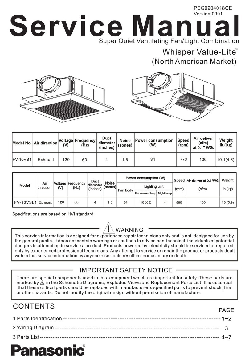
Panasonic Whisper Value-Lite FV-10VS1 Service manual
Soleus Air
Soleus Air FSM-40 operating instructions
Casablanca
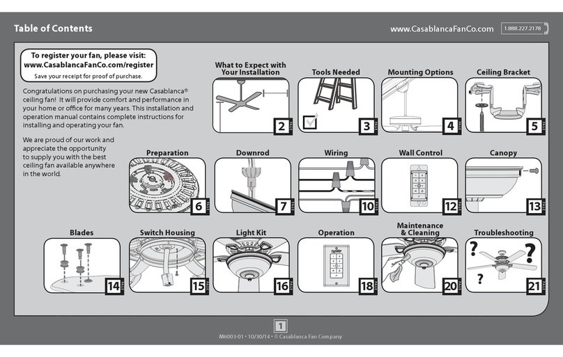
Casablanca Ainsworth 55005 user manual

Mitsubishi Electric
Mitsubishi Electric Lossnay VL-220CZGV-EB instruction manual

VonHaus
VonHaus 2500460 manual
