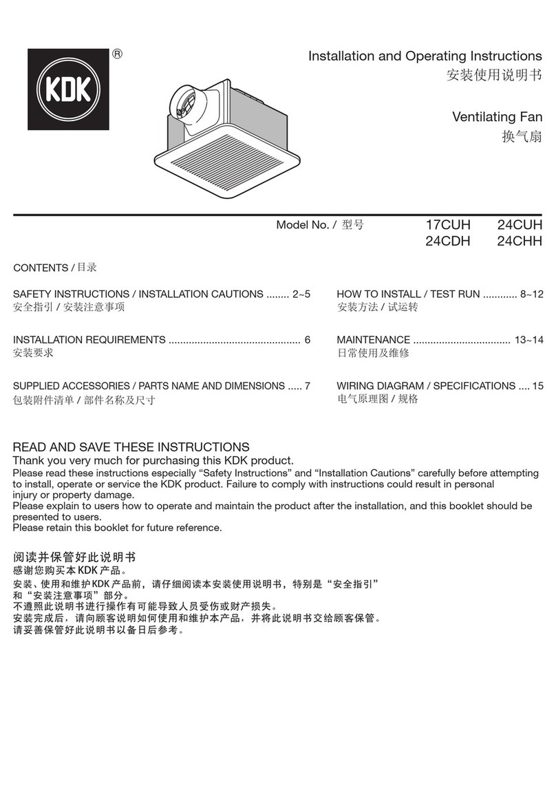
KDK E50DZUA User manual

Thanks for purchasing KDK「Energy Recovery Ventilator」.
●Please read this instruction carefully to understand how to use this product correctly before installation and construction,
especially「safety precautions」(page 3~5), (page 10~11) to make sure safe use. After you’ve read it, keep it well so that
you can easily find it if necessary.
●Please be sure to give this instruction to end users.
.KDK ﻥﻣ “ﺔﻗﺎﻁﻟﺍ ﺓﺩﺎﻌﺗﺳﺍ ﺔﻳﻭﻬﺗ ﺯﺎﻬﺟ” ﻙﺋﺍﺭﺷ ﻰﻠﻋ ﺍًﺭﻛﺷ
(30~29 ﺔﺣﻔﺻ) ،(24~22 ﺔﺣﻔﺻ) “ﺔﻣﻼﺳﻟﺍ ﺕﺎﻁﺎﻳﺗﺣﺍ” ﺔﺻﺎﺧﻭ ،ﺕﻳﺑﺛﺗﻟﺍﻭ ﺏﻳﻛﺭﺗﻟﺍ ﻝﺑﻗ ﺢﻳﺣﺻ ﻝﻛﺷﺑ ﺞﺗﻧﻣﻟﺍ ﺍﺫﻫ ﻡﺍﺩﺧﺗﺳﺍ ﺔﻳﻔﻳﻛ ﻡﻬﻔﻟ ﺔﻳﺎﻧﻌﺑ ﺕﺎﻣﻳﻠﻌﺗﻟﺍ ﻩﺫﻫ ﺓءﺍﺭﻗ ﻰﺟﺭﻳ ●
.ﺭﻣﻷﺍ ﻡﺯﻟ ﺍﺫﺇ ﺎﻬﻳﻟﺇ ﻝﻭﺻﻭﻟﺍ ﻝﻬﺳﻳ ﺙﻳﺣﺑ ﺍًﺩﻳﺟ ﺎﻬﺑ ﻅﺎﻔﺗﺣﻻﺍ ﻰﺟﺭﻳ ،ﺕﺎﻣﻳﻠﻌﺗﻟﺍ ﺓءﺍﺭﻗ ﺩﻌﺑ .ﻥﻣﻵﺍ ﻡﺍﺩﺧﺗﺳﻻﺍ ﻥﺎﻣﺿﻟ
.ﻥﻳﻳﺋﺎﻬﻧﻟﺍ ﻥﻳﻣﺩﺧﺗﺳﻣﻠﻟ ﺕﺎﻣﻳﻠﻌﺗﻟﺍ ﻩﺫﻫ ﻡﻳﺩﻘﺗ ﻥﻣ ﺩﻛﺄﺗﻟﺍ ﻰﺟﺭﻳ ●
Accessories ﺕﺎﻘﺣﻠﻣﻟﺍ
Model label .......................................1 piece
ﺔﻌﻁﻗ 1............................................ ﺯﺍﺭﻁﻟﺍ ﻕﺻﻠﻣ
Operation Instruction ........................ 1 book
ﺏﻳﺗﻛ 1.......................................... ﻝﻳﻐﺷﺗﻟﺍ ﺕﺎﻣﻳﻠﻌﺗ
(Please be sure to give them to customers)
(ﻝﻳﻣﻌﻠﻟ ﺎﻬﺋﺎﻁﻋﺇ ﻥﻣ ﺩﻛﺄﺗﻟﺍ ﻰﺟﺭﻳ)
Operation Instruction
(Included Installation Instruction)
Energy Recovery Ventilator
ﻝﻳﻐﺷﺗﻟﺍ ﺕﺎﻣﻳﻠﻌﺗ
(ﺏﻳﻛﺭﺗﻟﺍ ﺕﺎﻣﻳﻠﻌﺗ ﻥﻣﺿﺗﺗ)
ﺔﻗﺎﻁﻟﺍ ﺓﺩﺎﻌﺗﺳﺍ ﺔﻳﻭﻬﺗ ﺯﺎﻬﺟ
Model No. E25DZUA
E35DZUA
E50DZUA
ﺯﺍﺭﻁﻟﺍ ﻡﻗﺭ

2
CONTENTS
<Operation Instruction>
SAFETY PRECAUTIONS................................................................................. 3~4
SPECIAL ATTENTION ......................................................................................... 5
USING CONDITION·CAUTIONS ..................................................................... 5~6
FEATURES........................................................................................................... 6
USING CAUTIONS............................................................................................... 6
INSTALLATION DIAGRAM................................................................................... 7
PART NAME AND USING METHODS ............................................................. 7~8
HANDLING METHODS ON ABNORMAL OPERATION....................................... 8
MAINTENANCE METHODS ................................................................................ 9
<Installation Instruction>
SAFETY PRECAUTIONS............................................................................. 10~12
INSTALLATION DIAGRAM................................................................................. 13
PART NAME AND DIMENSIONS................................................................. 14~16
CONSTRUCTION METHODS...................................................................... 17~19
TRIAL OPERATION............................................................................................ 19
SPECIFICATION ................................................................................................ 20
ﺕﺎﻳﻭﺗﺣﻣﻟﺍ
<ﻝﻳﻐﺷﺗﻟﺍ ﺕﺎﻣﻳﻠﻌﺗ>
23~22 ................................................................................................. ﺔﻣﻼﺳﻟﺍ ﺕﺎﻁﺎﻳﺗﺣﺍ
24..................................................................................................................ﺍًﺩﻳﺟ ﻪﺑﺗﻧﺍ
25~24 .......................................................................................ﺕﺎﻬﻳﺑﻧﺗﻟﺍ.ﻡﺍﺩﺧﺗﺳﻻﺍ ﻑﻭﺭﻅ
25...................................................................................................................ﻑﺋﺎﻅﻭﻟﺍ
25.........................................................................................................ﻡﺍﺩﺧﺗﺳﻻﺍ ﺕﺎﻬﻳﺑﻧﺗ
26...........................................................................................................ﺏﻳﻛﺭﺗﻟﺍ ﻁﻁﺧﻣ
27~26 .....................................................................................ﻡﺍﺩﺧﺗﺳﻻﺍ ﺔﻘﻳﺭﻁﻭ ءﺯﺟﻟﺍ ﻡﺳﺍ
27...................................................................ﻲﻌﻳﺑﻁﻟﺍ ﺭﻳﻏ ﻝﻳﻐﺷﺗﻟﺍ ﺕﻻﺎﺣ ﻲﻓ ﺔﻌﺑﺗﻣﻟﺍ ﺕﺍءﺍﺭﺟﻹﺍ
28.........................................................................................................ﺔﻧﺎﻳﺻﻟﺍ ﺕﺍءﺍﺭﺟﺇ
<ﺏﻳﻛﺭﺗﻟﺍ ﺕﺎﻣﻳﻠﻌﺗ>
31~29 ................................................................................................. ﺔﻣﻼﺳﻟﺍ ﺕﺎﻁﺎﻳﺗﺣﺍ
32...........................................................................................................ﺏﻳﻛﺭﺗﻟﺍ ﻁﻁﺧﻣ
35~33 ................................................................................................. ﻩﺩﺎﻌﺑﺃﻭ ءﺯﺟﻟﺍ ﻡﺳﺍ
38~36 .......................................................................................................ﺕﻳﺑﺛﺗﻟﺍ ﻕﺭﻁ
38......................................................................................................... ﻲﺑﻳﺭﺟﺗﻟﺍ ﻝﻳﻐﺷﺗﻟﺍ
39................................................................................................................ﺕﺎﻔﺻﺍﻭﻣﻟﺍ

3
Operation Instruction
SAFETY PRECAUTIONS <must be complied>
In order to prevent the damage to users and other people and avoid the loss of property, please ensure
to comply with following cautions.
■Marks below are used to distinguish the damage from damage degrees caused by ignoring the
marks or operating by wrong methods.
WARNING This mark means the content「Please consider the
situation, it may cause the death or serious injury」.
CAUTION This mark means the content「Please consider the
situation, it may cause the injury or the loss of property」.
■The following marks represent the content expected to be complied (The following mark is an
example of mark indications).
The mark represent the content
(prohibition).
The mark represent the mandatory
content (must be complied).
WARNING
The appliance is not using by people (including
children) with reduced physical, sensory or
mental capabilities, or lack of experience and
knowledge unless they have been given
supervision or instructions concerning the use
of the appliance by a person responsible for
their safety. Children should be supervised to
ensure not playing with the appliance.
It may cause the electric shocks or
injuries.
Prohibition
Don’t insert fingers or stick into the unit near
air inlet and outlet.
It may cause the injury because of high
speed rotation inside the unit.
Please entrust the retail shop or specialized
company to conduct the maintenance except
the filter maintenance.
It may cause the firer , electric shocks
and injuries.
Wet hands
Prohibition
Don’t turn on/off the switch by wet hands.
It may cause electric shocks.
Prohibition
Don’t turn on/off the switch when combustible
gas leaks.
The sparks of switch may cause the gas
explosion.
Forbidden
to get wet
Don’t wash the unit by water.
It may cause short circuit or electric
shocks (motor, switch and other electric
parts).
Prohibition
It’s forbidden to conduct product
customization, disassembly and repairing.
Otherwise, it may cause fire, electric
shocks and injuries. If the product is
required to maintain, disassemble and
repair, please contact the shop where
you purchased.
Prohibition
It can’t be used for ventilation in locations with
open-burning appliances (heater).
It must be adopted with professional
ventilations if using the gas or petroleum
heatingstove in the room.
Please cut off the breaker in the
switch box before maintenance.
It may cause electric shocks.
This product is not intended for use by persons (including children) with reduced physical, sensory
or mental capabilities, or lack of experiences and knowledge, unless they have been given
supervision or instruction concerning use of the product by a person responsible for the safety.
Children should be supervised to ensure that they do not play with the product.
Make sure to shut down the power before cleaning the product.
●
●
●

4
Operation Instruction
Confirm if the unit is installed firmly.
It may cause injuries when dropping.
Prohibition
Don’t place the obstacles near the air inlet and
return air grille.
It may cause the injury due to the
blowing out or sucking in.
Prohibition
Don’t place the burning appliance in the
location where the unit blows directly.
It may cause the insufficient burning of
burning appliance.
Prohibition
Don’t incline it when disassembling the unit.
The internal accumulated water will wet
the things in the room.
Please contact the retail shop or repair
shop.
Firmly fix the parts.
Otherwise, droppings will cause the
injury.
The appliance must be stopped using
immediately until repaired when abnormal
operation occurs (such as noise, vibration,
burnt smell).
It may cause the unexpected accidents.
Please entrust the professional staff to conduct
electric, duct and equipment installation.
It may cause unexpected accidents
when improper installation occurs.
Please wear the gloves when cleaning the
filter.
It may cause the injury.
Because it’s aerial work, please fix the ladder
when conducting the maintenance.
Dropping may cause injury.
Conduct the routine cleaning to filter.
Owing to lots of dirt and dust attached in
the filter, it may cause the lack of oxygen
in indoor areas.
In maintenance (disassembling the
maintenance cover), please pay attention to
the dropping of dirt, dust and insects.
It may enter into eyes.
The appliance is forbidden to operate without
Filter Box Unit.
Otherwise dirt or dust will accumulate in
the energy recovery core. It will lower its
performance and dirt or dust will enter
into the room.
Please fully confirm the usage for special
purposes. The appliance is not used under
the special conditions such as preservation
of foods, animals, plants, precision
instruments, and artwork.
Otherwise, it may cause the quality
degradation.
Prohibition
Plant and animal cannot be placed near the
blowing air outlet.
It may cause the bad effects to animals
and plants.
Prohibition
Don’t use the unit near the combustible spray.
It may cause the fire.
Prohibition
Please don’t place the vessel with water on the unit.
It will wet the inside of unit when the water
leaks, which may damage the electric
insulation or cause the electric shock.
CAUTION
If the appliance is not going to be used for a
long time, in order to prevent dropping, it
should be well kept.
Otherwise, it may cause the dropping.
If the power supply cord appears worn, in
order to avoid the danger, changing work
should be done by authorized persons.
Please get the contact with the agent
where you purchased.
When the appliance is not used for a long
time, you should cut off the breaker for safety.
Dust accumulation will get the unit
heated, which may cause the fire.
Prohibition
Don’t clean the filter with volatile oil or metallic
brush.
It may damage the filter
when the dirt and dust
come into room, it will
enter eyes.
Metallic brush
Thinner
Gasoline
Volatile oil

5
Operation Instruction
SPECIAL ATTENTION
Don’t use it in the following locations.
Locations exposed to high temperature
or direct flame.
Avoid installing the ERV in locations
where reach temperature of 40°C or
above. Using under high temperature
conditions may cause distortion of the
filter or heat exchange core or motor
burn-out.
40°C
Locations with high humidity.
Do not install in high humidity
locations such as bathrooms.
Dew occurred in unit may cause
electric shocks, short circuit, other
electric accidents and produce the
dewing water drops.
Locations with large amount of
cooking smoke.
The unit doesn’t work if the filter or
heat exchange core is clogged with
oil, it may cause fire.
Cooking
smoke
Indoor air inlet
Don’t install the unit in locations such as machinery or chemical plants where it will be
exposed to noxious gases containing acids, alkali, organic solvents, paint fumes, etc., to
gases containing corrosive ingredients, or where dust or oil mist will be produced. (Gas
poisoning, corrosion and degradation accrued in unit may cause the fire.)
USING CONDITION·CAUTIONS
■Using condition
●Outdoor air condition
Temperature range -10°C~+40°C, relative humidity 85% or less.
●Indoor air condition
Refer to the indoor air condition of living room.
●Installation requirements:
Same as the indoor air conditions.
Indoor air here means air in air-conditioned living rooms. The appliance
usage in refrigerators or other places where temperature can fluctuate
greatly. It is prohibited even if a temperature range is acceptable.
■Be careful of frost and dew
As shown in the right figure, it’s supposed that a high temperature absorbing air condition A and a low
temperature absorbing air condition B are plotted on the air line figure, then a high temperature air A is
heat-exchanged by the unit and Point C represents the trend of saturation curve .In this case, it will cause
the dew or frost inside the unit. To avoid this, you are required to heat a low temperature air B up to B’ so
as to get C’ below the saturation curve before using the unit.
■The Energy Recovery Ventilator manufactured by our company is conducted the condensation without the
water dropping test in the following conditions based on JIS B 8628:2003, if using condition is tougher than
the following sheet, it may cause the frost or dew.
JIS B 8628:2003 Energy Recovery Ventilator Appendix 5 (specification) condensation test method
Classific
ation
noitidnocroodtuOnoitidnocroodnI
Operation
status
Measured
time (h)
dry-bulb
temperature
wet-bulb
temperature
*relative
Humidity
(reference)%
dry-bulb
temperature
wet-bulb
temperature
*relative
Humidity
(reference)%
Cooling in
summer
22°C 17°C 60 35°C 29°C 65 operate 6 hours
Heating
in winter
20°C 14°C 50 –5°C – – operate 6 hours
Heating
in winter
20°C 14°C 50 –15°C – – Stop 6 hours
Relative humidity is calculated according to JIS B 8628:2003.
Absdute humidity (kg/kg')
B'
C'
A
Saturation curve
Dry-bule temperature (◦C)
C
B

6
Operation Instruction
FEATURES
1. Energy saving ventilation Thanks to efficient recovery of the thermal energy lost during
ventilation (fresh air load), you can save the air-conditioning fee.
2. Facility saving Thanks to a great reduction of fresh air load, part of the thermal energy
is recovered so that the airconditioning can become mini-type properly.
3. Humidity function When cooling, reduce the outdoor air humidity to make the incoming
air humidity close to the indoor humidity.
4. Comfortable ventilation Indoor temperature fluctuation is small when ventilating. As the
simultaneous performance of exhaust air and supply air, it can be
ventilated in high density space.
5. Sound isolation The air duct and heat exchange core has the effect of sound isolation.
It prevents the outdoor noise from entering into the room and keeps
the indoor sound from spreading for not breaking the nice atmosphere
such as in the office or store.
USING CAUTIONS
Avoiding the coming of insects
Energy Recovery Ventilator is intended to exchange outdoor air and indoor air. When the outdoor
air comes in, it may bring the insects from outdoor pipe hood to internal unit.
As insect occurrence is affected by natural environment, it’s recommended to use the pipe hood with
fly nest when using the unit under the environment with many insects such as near the street light.
It must operate with Filter Box Unit.
If not using the Filter Box Unit, heat exchange
core is clogged with dirt and dust, performance
will be lowered and even the unit doesn’t work.
Turn on /off the switch correctly.
Repeatedly turning on or off the switch not only
cause wrong operations but also affects the
relay inside and damage it.
Recommend to stop the unit in the high density
of dust such as sandstorm.
If the filter is clogged in
short time, it will not be
work under the normal
ventilation. In addition,
under the condition of
high indoor density of
dust, even if the filter is
purified, part of the dust
will enter into the room
together with the fresh air.
It’s forbidden to use the「normal ventilation」
since the dew will be produced in unit and
indoor air inlet if operating the mode「normal
ventilation」when the room is heated in winter.
Winter
normal
ventilation
Stop

7
Operation Instruction
INSTALLATION DIAGRAM
PART NAME AND USING METHODS
(model label adhesive location).
■Part Name
Exhaust air
Outside air
Outdoor Indoor
Supply air
Filter Box Unit Energy Recovery
Ventilator
Remote
control
Return air
Inside the
ceiling
Indoor filter
Heat exchang core
Maintenance cover
Switch box
Model label

8
Operation Instruction
PART NAME AND USING METHODS
(model label adhesive location).
■Using methods:
Please use the switch mounted on the wall
(separately sold).
On
High
Heat
exchange
Off
Low
Normal
ventilation
Heat exchange:
It heat-exchanges the outdoor air and indoor air to get the temperature and humidity of outdoor close
to indoor first, then begins to supply the fresh air to the room.
Normal ventilation:
In case the indoor air is polluted, exhaust air volume will be increased to facilitate the emission of
polluted air.
Caution: With the exhaust air amount increasing, the negative pressure will be produced in room, the
outdoor air comes into the room from the gaps of door, window and etc., so if you don’t expect the
outdoor air to come into the room, don’t use the mode.
HANDLING METHODS ON ABNORMAL
OPERATION
■If treated as fault:
Please check as the following list, if abnormal operation occurs, you should turn off the switch the
breaker, and contact with retail shop or repair shop.
Situation Solution
●The unit doesn’t work with
power on.
●Without air blowing.
●Is the breaker in the mode「off」?
●Is there a power failure?
●Is the filter clogged with dust (please conduct the maintenance
according to the maintenance methods for each model)?
If the condition is not improved or changed after checking the above-mentioned solution, please
contact with retail shop where you purchased.
●Please use the mode「heat exchange」
when stopping.
●In winter, please use the mode「heat
exchange」.
●In winter, when the room is heated and the
operation in the mode「normal ventilation」,
condensation occurs on the surface of the
unit, which will make the ceiling dirty or
cause the short circuit or electric leakage.
ATTENTION

9
Operation Instruction
MAINTENANCE METHODS
■Maintenance methods for Filter Box unit
●Refer to the instruction of Filter Box unit to maintain.
ERV Model No. Filter Box Unit Model No.
E25DZUA BE25DZUA
E35DZUA
E50DZUA BE50DZUA
■Maintenance methods for main unit
1. Opening methods of side maintenance cover
Remove the screws fixed in maintenance cover
by screwdriver.
Support the maintenance cover by hand and
rotate the two butterfly bolts by 90°, remove the
maintenance cover toward the arrow A.
2. Cleaning methods of indoor filter
1) Remove the indoor filter horizontally (Circle ).
2) Please clean the dirt and dust attached to indoor
filter by vacuum cleaner.
Note: indoor filter cleaning: once a month, using
life is about 12 months.
3) Please conduct indoor filter installation by the
reverse order of disassembling steps.
ERV Model No. Replacement filter Model No.
E25DZUA FB25DZUA
E35DZUA FB35DZUA
E50DZUA FB50DZUA
Butterfly bolt
Heat exchange core
Screws
Side maintenance door
Indoor filter
●After using the ERV for a long time, filter will be clogged by dirt and dust which will reduce the air
volume and ventilation effect, also get noisier. Please do the routine cleaning depending on the
how dirty it is.
●Tough using conditions (locations with large amount of dust) will cause the reduction of air
volume and filter efficiency, to keep the unit perform well, please clean it frequently or replace the
filter properly. If using condition continues to get worse, in order to prevent the polluted air from
coming into the room, please adjust to the low mode for reducing the air volume or stop the unit.
●In maintenance, please cut off the breaker before disassembling the maintenance cover.
●Please conduct the cleaning after fixing the ladder and wearing the gloves.
●Please pay attention to the dropping of parts and dirt such as filters screws, dust or insects.
ATTENTION

10
Installation Instruction
SAFETY PRECAUTIONS <must be complied>
In order to prevent the damage to users and other people and avoid the loss of property, please ensure
to comply with following cautions.
■Marks below are used to distinguish the damage from damage degrees caused by ignoring the
marks or operating by wrong methods.
WARNING This mark means the content「Please consider the
situation, it may cause the death or serious injury」.
CAUTION This mark means the content「Please consider the
situation, it may cause the injury or the loss of property」.
■The following marks represent the content expected to be complied (The following mark is an
example of mark indications).
The mark represent the content (prohibition).
The mark represent the mandatory content (must be complied).
WARNING
Don’t use the power except 220V/ 60Hz.
It may cause the fire and electric shock.
Please turn off the breaker in maintenance,
inspection and no use for a long time.
It may cause the electric shock and injury.
Ground connection construction
Please conduct the ground connection in the following methods.
If using other methods, it may cause the insufficient
ground connection.
Don’t connect the ground connection with gas pipeline,
water pipeline, lightening rod and phone landline. Wrong
ground connection may cause electric shocks.
Ground
connection
●When connecting lead wire to the ground
terminal of outlet.
Plug (outside
the bathroom)
Ground wire (diameter of copper
wire is 1.6 mm or above.
Ground
terminal
ERV
●When using the ground bar.
ERV
Ground wire (diameter of copper
wire is 1.6 mm or above.
Ground bar
(separately buy)
30 cm above
(select the location with humidity)
Fault or electric leakage may cause the electric shock.
When metallic air duct go through metal mesh
used for mortar, wire braid, or wood material
adhesive to the metal plate, don’t get in touch
with them.
It may cause the fire if electric leaks.
Any exhaust air can’t be supplied to outdoor
air inlet such as combustible air.
It may cause the serious accident owing
to lack of oxygen.
Please entrust the retail shop or professional
staff where you purchased to conduct the
installation.
When you install it by yourself, it may
cause the fire, electric shock and injury.
Outdoor air inlet cannot be installed in locations
where exhaust air may blow reversibly.
It may pollute the indoor air and harm
our health.
Strictly conduct the installation according to
the installation instruction.
Improper installation may cause the
electric shock or fire.
Prohibition
Don’t conduct the product customization.
It may cause the fire, electric shock and
injury.

11
Installation Instruction
CAUTION
Prohibition
Don’t install the main unit and indoor air inlet
in location with high temperature or directly
exposed to heat source.
It may heat or cause the fire.
Please install the anti-bird nest or similar
accessory in air duct.
Please remove the abnormality such as
bird nets, otherwise it may cause the
lack of oxygen in rooms.
Please connect according to the electrical
equipment technology benchmark and indoor
lead wire regulation.
Wrong wire connection will cause the
electric leakage, electric shock and fire.
Owing to different installation positions for
special purpose circuit breaker, sometimes it’s
required to install the anti-creeping circuit
breaker.
It may cause the electric leakage if not
installing the anti-creeping circuit
breaker.
The air duct which connects the outdoor to
indoor should be prevented to occur the dew.
Improper installation will cause the water
leakage in room, result in damaging the
indoor property.
Firmly fix the parts.
Dropping may cause the injury.
Please install the pipe hood for preventing
strong wind from outside (separately buy).
Please stop the unit during the strong
wind and sandstorm as they may enter
the room along the air duct.
MCX100K Circular pipe hood
For project: With fly
nest & without fly nest
Contact
prohibition
Please don’t insert the fingers and stick into
the rotation part during the operation.
It may cause the injury.
Prohibition
Please don’t set the indoor air inlet in locations
with high temperature or high humidity.
It may cause the damage inside the unit,
which can result in abnormal operation,
electric shock and fire.
Prohibition
Don’t install the main unit and indoor air inlet
in locations with excessive cooking smoke
such as kitchen.
It may cause the fire.
Please install it on the ceiling that is strong
enough to hold the unit, otherwise the ceiling
should be reinforced.
Besides, please install the unit by the
specified methods.
Dropping may
cause the injury.
Prohibited to
use in location
with water
Please don’t install it in the high humidity place
such as bathroom.
It may cause the electric shock and
abnormal operation.
Please install inside the insulated space (the
space is insulated from outdoor air).
If installing it outside the insulated space
(the space exposed to the outdoor air), the
internal unit will be dewed in winter, it may
cause the electric shock or water dropping.
Please install the outdoor air duct in a inclined way
Improper installation will cause the water
seepage in the room and wet the goods.
Please install the main unit in locations where
dust and dirt can’t come in.
Large amount of dirt and dust clogged in
filter will cause the lack of oxygen in rooms.
Specified part must be used during the
installation (include the accessories).
It may cause the unit dropping, fire and
electric shock If not using the specified
parts.
The appliance is forbidden to operate without
Filter Box Unit.
Otherwise dirt or dust will accumulate in
the energy recovery core. It will lower its
performance and dirt or dust will go into
room.

12
Installation Instruction
SAFETY PRECAUTIONS <must be complied>
CAUTION
■Please avoid the following duct installation.
(1) excessive bending
Prohibition
(2) multi-times bending
Prohibition
(3) changing the diameter of
connecting duct
Prohibition
■It may cause the unexpected accident.
Prohibition
Don’t install the unit in locations such as
machinery, chemical and research plant where
it will be exposed to noxious gases containing
acids, alkali, organic solvents, paint fumes,
etc., to gases containing corrosive ingredients.
It may cause the gas poison, corrosive
damage and deterioration inside the
unit, Result in fire.
Prohibition
Please don’t install the unit in locations where
indoor temperature is below the outdoor
temperature.
It may cause the electric shock or
abnormal operation.
Prohibition
Please don’t face to the air outlet with eyes
(especially when operating).
The dirt may enter your eyes.
Prohibition
Don’t use it in location with opening-burning
equipment (heater).
Please use the professional ventilation
when the room is heated by gas or oil
heating furnace.
Prohibition
Do not install in high humidity locations such
as bathrooms.
Dewing occurred in unit may cause
electric shock, short circuit, other electric
accident and dewing water drops.
Prohibition
Don’t insert fingers or stick into the unit of air
inlet, air outlet.
It may cause the injury because of high
speed rotation inside the unit.
Prohibition
Don’t install in location where may be exposed
to the combustible gas leakage.
In case of gas get together around the
unit, it may cause the fire.
Prohibition
Don’t twist the unit or conduct the overload
force to unit in construction.
Dropping may cause the injury.
Please install the ventilation equipment on the
ceiling with excessive humidity or high
temperature.
It may cause the fire or electric shock.
Please fully confirm the usage for special
purposes.
If the product is used for special purposes
such as preservation of food, animals,
plants, precision instruments and artwork,
it may cause the quality declination.
Use the specified cord connecting the power
supply cord and connect wire; terminal in
connection is fixed firmly and not affected by
cord forces.
Firmly fix the power supply cord and connect
wire, close the cover, and don’t make the cover
raised. If the cover is not closed firmly, dust
and dirt will get in and being heated by terminal
in connection, result in fire or electric shock.
Please take care when moving the unit.
Improper hanging and moving may
cause the dropping, result in injury.
Please pay attention to the rotation of impeller
caused by backward air in air duct.
Although the power is cut off, it may get
involved to the rotation part, result in
injury.
Please wear the gloves and other protective
tools in construction to avoid the injury.

13
Installation Instruction
INSTALLATION DIAGRAM
Cautions
●It’s recommended to install the pipe cover for strong wind prevention form outside. Please stop the
unit during the strong wind and sandstorm as they may enter into the room along the air duct.
●Please carefully read the instruction for parts which are sold separately during the construction.
●Handle the thermal insulation to duct.
1. The Outside air is cold in winter, but the dry air comes into the duct, dew will occur in the external
duct.
2. The Exhaust air is warm in the room, but the damp air goes out of the room, dew will occur in the
internal duct.
In the conclusion, the outdoor duct should be conducted with thermal insulation.
●The air duct which connects the filter box unit to ERV is suggested to install horizontally.
SA
(Supply
Air)
Ceiling suspension bolt Room air duct
Pipe hood
OA
(Outside
Air)
(Outside Duct)
EA (Exhaust Air)
RA
(Room Air)
Grille
(market goods)
Energy Recovery
Ventilation
(E25DZUA)
(E35DZUA)
(E50DZUA) Filter Box
(separately sold )
(BE25DZUA)
(BE35DZUA)
Duct with
thermal
insulation
(market goods)
Duct with thermal
insulation
(market goods)
RA
(Return air) Remote control
(separately sold)
EB90SA
Maintenance
cover Outdoor pipe cover
(market goods)
(for strong wind
prevention )
SA
(Supply air)
OA
(Outside air)
EA
(Exhaust Air)

14
Installation Instruction
PART NAME AND DIMENSIONS
*1. Dimension of maintenance door.
*2. Suspension point dimension
*3. The below-mentioned dimensions for maintenance door are
recommended to use if customers choose to remove the filter unit for
maintenance,
when the inside height of ceiling is over 600mm, dimension for
maintenance door should be:450mm*450mm
when the inside height of ceiling is less than 600mm, dimension for
maintenance door should be:600mm*600mm
1. Duct size (Nominal Diameter): Ø150/Ø200 (OA: Ø200; other: Ø150).
2. The above dimensions do not include the thickness of the insulation
material in the unit
■Be careful of dew and frost
1. The two outside ducts must be insulated to prevent condensation.
(Material: Class wool. Thickness: 25 mm)
2. Outside air may come into the room in cold area and place where
outside air speed is high.
3. In order to prevent the water ingress , install the two outside ducts
inclined to outside
4. As shown in the figure, suppose a high temperature absorbing air
condition A and a low temperature absorbing air condition B are
plotted on the air line figure, then a high temperature air A is heat-
exchanged by the unit and goes out of the saturation curve as shown
by point C .In this case, the unit will be dewed or frosted. To avoid
this, you are required to heat a low temperature air B up to B’ so as to
get C’ below the saturation curve ,before using the unit.
NO. Part name Q’ty Material Remarks
1 Frame 1 Galvanized steel sheet
2 Adapter 4 ABS
3 Impeller 2 PP
4 Fan motor 1
5 Heat exchange core 2 Special paper + resin
6 Indoor filter 2
7 Ceiling suspension 4 Galvanized steel sheet
8 Switch box 1 Galvanized steel sheet
9 Filter Box Unit -
E25DZUA
2
3
4
5
6
7
8
1
UNIT: mm
Ceiling
suspension parts
Internal structure after
opening the maintenance cover
(Outside Air)
(Exhaust Air) (Supply Air)
(Room Air)
■Maintenance Dimension
It must be set the maintenance door , and clean the
filter and heat ex change core as specified in instruction.
*1
9 9
*1
*1
*1
The area within double point chain
line is reserved for maintenance,
it's prohibited to place other devices.
Installation method for case 1 Installation method for case 2
The area within double point chain
line is reserved for maintenance,
it's prohibited to place other devices.
*1
*1
*1
*1
*3
*3
*3
*3

15
Installation Instruction
PART NAME AND DIMENSIONS
*1. Dimension of maintenance door.
*2. Suspension point dimension
*3.The below-mentioned dimensions for maintenance door are
recommended to use if customers choose to remove the filter unit for
maintenance,
when the inside height of ceiling is over 600mm, dimension for
maintenance door should be:450mm*450mm
when the inside height of ceiling is less than 600mm, dimension for
maintenance door should be:600mm*600mm
1. Duct size (Nominal Diameter): Ø150/Ø200 (OA: Ø200; other: Ø150).
2. The above dimensions do not include the thickness of the insulation
material in the unit
■Be careful of dew and frost
1. The two outside ducts must be insulated to prevent condensation.
(Material: Class wool. Thickness: 25 mm)
2. Outside air may come into the room in cold area and place where
outside air speed is high.
3. In order to prevent the water ingress , install the two outside ducts
inclined to outside
4. As shown in the figure, suppose a high temperature absorbing air
condition A and a low temperature absorbing air condition B are
plotted on the air line figure, then a high temperature air A is heat-
exchanged by the unit and goes out of the saturation curve as shown
by point C .In this case, the unit will be dewed or frosted. To avoid
this, you are required to heat a low temperature air B up to B’ so as to
get C’ below the saturation curve ,before using the unit.
NO. Part name Q’ty Material Remarks
1 Frame 1 Galvanized steel sheet
2 Adapter 4 ABS
3 Impeller 2 PP
4 Fan motor 1
5 Heat exchange core 2 Special paper + resin
6 Indoor filter 2
7 Ceiling suspension 4 Galvanized steel sheet
8 Switch box 1 Galvanized steel sheet
9 Filter Box Unit -
E35DZUA
3
4
5
6
7
8
2
1
(Exhaust Air)
(Outside Air)
(Supply Air)
(Room Air)
Ceiling
suspension parts
■Maintenance Dimension
It must be set the maintenance door , and clean the
filter and heat exchange core as specified in instruction.
UNIT: mm
Internal structure after
opening the maintenance cover
9 9
Installation method for case 1 Installation method for case 2
The area within double point chain
line is reserved for maintenance,
it's prohibited to place other devices.
The area within double point chain
line is reserved for maintenance,
it's prohibited to place other devices.
*1*1
*1
*1
*
1
*1
*1
*1
*3
*
3
*3
*
3

16
Installation Instruction
PART NAME AND DIMENSIONS
*1. Dimension of maintenance door.
*2. Suspension point dimension
*3.The below-mentioned dimensions for maintenance door are
recommended to use if customers choose to remove the filter unit for
maintenance,
when the inside height of ceiling is over 600mm, dimension for
maintenance door should be:450mm*450mm
when the inside height of ceiling is less than 600mm, dimension for
maintenance door should be:600mm*600mm
1. Duct size (Nominal Diameter): Ø200.
2. The above dimensions do not include the thickness of the insulation
material in the unit
■Be careful of dew and frost
1. The two outside ducts must be insulated to prevent condensation.
(Material: Class wool. Thickness: 25 mm)
2. Outside air may come into the room in cold area and place where
outside air speed is high.
3. In order to prevent the water ingress , install the two outside ducts
inclined to outside
4. As shown in the figure, suppose a high temperature absorbing air
condition A and a low temperature absorbing air condition B are
plotted on the air line figure, then a high temperature air A is heat-
exchanged by the unit and goes out of the saturation curve as shown
by point C .In this case, the unit will be dewed or frosted. To avoid
this, you are required to heat a low temperature air B up to B’ so as to
get C’ below the saturation curve ,before using the unit.
NO. Part name Q’ty Material Remarks
1 Frame 1 Galvanized steel sheet
2 Adapter 4 ABS
3 Impeller 2 PP
4 Fan motor 1
5 Heat exchange core 2 Special paper + resin
6 Indoor filter 2
7 Ceiling suspension 4 Galvanized steel sheet
8 Switch box 1 Galvanized steel sheet
9 Filter Box Unit -
E50DZUA
1
2
3
4
5
7
8
6
Internal structure after
opening the maintenance cover
Ceiling
suspension parts
(Exhaust Air)
(Outside Air)
(Supply Air)
(Room Air)
■
Maintenance Dimension
It must be set the maintenance door , and clean the
filter and heat exchange core as specified in instruction.
UNIT: mm
99
Installation method for case 1 Installation method for case 2
The area within double point chain
line is reserved for maintenance,
it's prohibited to place other devices.
The area within double point chain
line is reserved for maintenance,
it's prohibited to place other devices.
*
1
*
1
*
1
*
1
*
1
*
1
*
1
*
1
*
3
*
3
*
3
*
3

17
Installation Instruction
CONSTRUCTION METHODS
■Construction method
1 Installation of main unit and air duct
Install 4 ceiling suspension bolts (separately buy: M10)
●Please align the suspension bracket of main unit with ceiling suspension bolts.
Installation method for case 1 Installation method for case 2 Installation method for case 2Installation method for case 1
E25DZUA E35DZUA
●Please adjust the length of ceiling
suspension bolt to ensure the distance
between the downside of unit and ceiling is
over 25 mm, the distance between the upside
of unit and the mounting face of ceiling
suspension bolts is over 20 mm.
1. Situation with the same height of ceiling.
*Consider the situation in which ERV is
installed in conjunction with filter box unit, the
height of ceiling must comply with the
requirement of filter box unit.
above
20mm
above
25mm
Filter Box Unit Energy Recovery Venlator
Adhesive tape Insulaon material
(adaptor and aluminum tape
is requested to insulate.)
ERV Model No. Main unit height
(mm)
Filter Box Unit
Model No.
Main unit height
(mm)
E25DZUA 220 BE25DZUA 240
E35DZUA 230
E50DZUA 240 BE50DZUA 350
2. the height of ceiling varies with different
installation place.
*The air duct which connects the filter box
unit to ERV is suggested to install
horizontally.
above
20mm
above
25mm
above
20mm
above
25mm
Filter Box Unit Energy Recovery Venlator
Adhesive tape Insulaon material
(adaptor and aluminum tape
is requested to insulate.)
Installation method for case 1 Installation method for case 2
E50DZUA
Install the ceiling suspension parts to its bolts.
●Please correctly install the direction of
outside air duct.
●Never fail to install the direction of unit
(ensure the ceiling suspension is above).
●Fix the screws and washers (separately buy).
●Install the unit horizontally.
Ceiling suspension parts
Nut
Washer
Seal the junction of an adaptor and a duct by
adhesive tape or seal tape (separately buy)
to prevent any air leakage.
●Please don’t touch the fan motor with hand
during the air duct construction.
●Install the ducts (2 pieces ) connected with
outside shall incline to outside (gradient:
1/100~1/50).
Gradient
Adhesive tape
Insulation material
(adaptor and aluminum tape
is requested to insulate.)
Outside air duct, exhaust air duct
1/100~1/50)
●Conduct the insulation to outside of two ducts
connected with outdoor.

18
Installation Instruction
2 Connection with power(Connection before ceiling construction)
■Wire connection diagram
■Wiring Diagram
7
6
8
2
4
2
1
5
4
6
7
3
3
4
1
22
1
4
3
8
8
7
2
3
1
5
6
2
3
1
4
5
6
4
5
3
1
Damper
Motor
White
Blue
Black
Yellow
White
Black
Orange
Red
Yellow
Blue
White
Limit Switch
Black
Yellow
White
Red
Capacitor
Yellow
Blue
Black
Yellow
White
Yellow
Red
Connector Connector
Connector
Orange
Black
Blue
White
Black
Gray
Red
Brown Brown
Black
Black
Black
Black
Black
Black
Black
Black
Black
Blue
White
White
White
Red
Gray
Orange
Orange
Black
Relay 3
Relay 2
Relay 1
Connector
A2
A1
Damper
HI
LO
COM
SW2
SW1
N
L
Aircon
Aircon
Power
Aircon
Controller
Switch
(Customer Preparing)
Power
Source
Double Pole Switch
(Customer Preparing)
(Contact Point Separate
Distance Over 3 mm)
Main Unit
Terminal Block
No Voltage a
Contact Point
Second Main Unit
Terminal Block
LNSW1 SW2 COM LO HI Damper A1 A2
Third Main Unit
k
c
a
lB
Black
Motor
220V~
60Hz
220V~
60Hz
Black
( )
SH
( )
HI
( )
LO
Precaution during the wire connection:
●The dashed line as shown in the figure must be conducted on spot by construction personnel.
●Please use the switch, its contact point separate distance is above 3 mm.
●Please use the switch, its rate current is above 10A..
●Recommended to use the wire for connecting power supply cord and switch, its rate voltage is
300V/500V as stipulation of 60227 IEC 53 (soft wire).
At this time, please use the three-core wire containing green/yellow wire for power supply cord;
besides, use the two-core wire for connecting SW1, SW2 and switch inside the unit; use the
two-core wire for Air-con operation(please omit the connection if it’s not used the Air-con
operation);use the four-core wire for connecting other terminal parts and switch, the nominal
cross-section area for above-mentioned wire is 2.5 mm2.When it’s used the remote control for
switch, the wire connected with switch, its cross-section area is 1.5 mm2.
●Please use the torque below the 1.2 N to firmly connect the lead wire and terminal parts, no
loosen of connection. Please note the power supply cord in connection is not adhesive with solder.
●Air volume can be adjusted to two modes of high/low and strong/low. Factory setting is mode of
high + low. Please adjust it as customer required if necessary.
●When adjusting the air volume from high to strong, please separate the connector of the red line
and the blue line, and link the connector of red wire and white wire (shown as chain dotted line).
●If several units operate together, the total current for all equipment must be less than the half rate
current of switch.
●Ground connection is required.
●After completing the wire connection, please fix the cover of switch box by the screws.
●When the power supply cord is damaged, in order to avoid the danger, please entrust the
authorized personnel to conduct the changing work, and get the contact with the sale shop and
repair shop where you purchased.

19
Installation Instruction
●Under the situation of Aircon operation
unavailable Available operation
With
Aircon
Button Button Button
Without
Aircon
–Button Button Button
Remove the cover of switch box.
●Remove the three screws fixed in the
cover of switch box.
The screws fixed
in the switch box
Wire connection.
●Peel off the skin of power supply cord by
40 mm, and peel off the skin of each core
wire by 10 mm.
10 mm
40 mm
On
High
Heat
exchange
Off
Low
Normal
ventilation
Model label
●The power supply cord goes through the wire plug,
as required in figure, fix the wire connecting power
supply cord and switch in the terminal block, and
fix the ground wire in the ground terminal.
●The joint should not be pressured, use specified
tools to fix the wire which links the power supply
cord to switch.
●In maintenance, in order to avoid pulling the switch
box into the unit, please keep enough space for
the wire connecting the power supply cord and
ground wire. To prevent it from touching the
ceiling, please fix it by ceiling suspension bolts.
Power supply cord (remain 50 cm)
Wire plug M4 Nut
Ground
terminal
Terminal
block
Fix the cover of switch box
●After completing the wire connection, fix the
cover of switch box by screws.
(dust and moisture may cause the electric
leakage or fire.)
TRIAL OPERATION
●After completion, never fail to check the ground wire connection and wiring and conduct the trial operation.
●Check the display of switch and airflow condition with power on after confirming the wiring
connection, power and voltage.
Switch On /Off Ventilation/stop
Air volume High/low Confirm the air volume is changed as the power on/off
Heat exchange/
Normal ventilation
Damper
closed/
open
Heat exchange (see the damper closed by opening side
maintenance door)
Normal ventilation (see the damper open by opening side
maintenance door)
●Abnormal operation occurs, cut off the special purpose circuit breaker and confirm the wire connection again.
●Fix the cover of switch box after conducting the trial operation.
●Please stick the model label to the switch or around.
Model label is placed in the plastic bag, don’t forget to attach it.

20
Installation Instruction
SPECIFICATION
Model No. Notch Watts
[W]
Current
[A]
Air
Volume
(m3/h)
External
Static
Pressure [Pa]
Temperature Exchange
Efficiency [%]
Enthalpy Exchange
Efficiency [%]
Noise
[dB (A)]
Weight
[kg]
Cooling Heating Cooling Heating
E25DZUA
SH 157 0.71 250 90 60 75 61 67 33 30
H 148 0.67 250 40 60 75 61 67 33
L 82 0.37 150 0 65 77 70 74 26
E35DZUA
SH 282 1.28 350 100 53 78 66 71.5 37 39
H 253 1.15 350 18 53 78 66 71.5 36.5
L 172 0.78 255 0 53 79 67 73 30.5
E50DZUA
SH 376 1.71 500 60 53 78 66 70 38 45
H 349 1.59 500 0 53 78 66 70 37.5
L 215 0.98 350 0 58 78 66 72 32
1. The above parameters are measured under the operation of assembly of ERV and Filter Box Unit.
2. The input power, the current and the exchange efficiency are measured at the standard air volume.
3. The input power indicated in name plate is the maximum value at the static pressure of 0 Pa.
4.
The noise is measured 1.5 m away from the bottom face of the unit.
The noise value measured at the total acoustic r
o
om is more than the indicated value in actual
5. The above parameters are measured according to standard JIS B 8628.
Model No.
Inches of H2O
CFM AT Static Pressure (ps-inches of H2O) Watts
E25DZUA 220V
E35DZUA
E50DZUA
Frequency
220V
220V
60Hz
60Hz
60Hz
CFM(OA-SA)
CFM(RA-EA)
183
0
130
Watts
For AMCA For IEC
RPM
CFM(OA-SA)
CFM(RA-EA)
CFM(OA-SA)
CFM(RA-EA)
Voltage
0.1
0.125
0.25
0.375
0.5 0.75 1 1.25 1.5 1.75
258
192
339
253
172
118
250
183
330
241
168
115.5
247
180
326
238
155
104
237
169
314
224
143
91
225
157
303
207
131
77
211
144
290
190
108
44
174
116
261
154
77
0
144
84
230
117
14
-
118
49
188
82
-
-
69
0
134
41
-
-
-
-
80
-
1448
1387
1425
1402
1501
1452
197
187
348
342
470
443
171
310
406
The ratings shown are based on tests and procedures performed in accordance with AMCA Publication 211.
※The Watts rating is only for AMCA test method and it is at the static pressure of 0 inch of H2O.
※※The Watts rating is only for IEC test method.
Voltage 220V / Frequency 60Hz
AMCA Specification
■
■
※※※
(The parameters below in the table are measured at notch of SH under the operation of ERV.)
operation.
This manual suits for next models
2
Table of contents
Other KDK Fan manuals
Popular Fan manuals by other brands

Lasko
Lasko R16610 operating manual

Temspec
Temspec VHC Series Operation & maintenance manual

Ebmpapst
Ebmpapst A2S130-AA03-39 operating instructions

Sencor
Sencor SFN 4044WH user manual

Monte Carlo Fan Company
Monte Carlo Fan Company 5CQM52XX-L Series Owner's guide and installation manual

Nuaire Group
Nuaire Group XBOXER-MICRO Installation and Maintenance

Nederman
Nederman N Series user manual

Lifebreath
Lifebreath PURE PERFORMANCE RNC5-HEX installation guide

NuAire
NuAire XBOXER XBC 10 NT Series INSTALLATION, CONTROL DETAILS, OPERATING AND MAINTENANCE

Helios
Helios RRK Series manual

Mitsubishi Electric
Mitsubishi Electric EF-35UDT-GL quick start guide

Vents
Vents VKM Series user manual