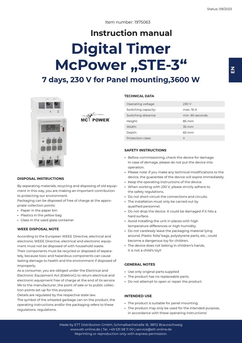
MICRO-AIR T2 User manual

INPUT CONFIGURATION
The T2 is pre-configured for resistive inputs and cannot be changed. The
resistive inputs allow for thermistors and also the pushbutton overrides.
T2
2 CHANNEL TIME SWITCH
PRODUCT DESCRIPTION
The MiG T2 is a dual channel programmable 365-day time switch, with daylight
saving, single and block holidays, temperature optimisation start, after hour’s
pushbutton override and temperature override. The T2 can accept up to two
temperature and two pushbutton inputs at a time. The T2 is able to be programmed via
the six front panel buttons and has an easy to follow menu. Alternatively the T2 it can
be programmed by using the PC Interface Software. All MiG’s have a controlled
temperature range of between -30°C to 110°C.
It is recommended that the T2 not be mounted in direct sunlight or within 500mm of
contactors, large power cables or any other devices that create an arc when switching.
It is recommended that they not be mounted outdoors or in direct sunlight. They should
be mounted in a well-ventilated area where the ambient air temperature is between
+5°C & 40°C. They should also be operated with a maximum relative humidity of
80% for temperatures up to 31°C (decreasing linearly to 50% at 40°C at altitudes above
2000 metres) and in an atmospheric pressure of between 86kPa (860mbar) and 106kPa
(1060mbar).
The T2 is rated at 24/230V~; 300mA/30mA @ 50/60Hz.
The T2 is covered by a 2-year warranty on parts only. (Ver 1.1)
MICRO AIR PTY LTD
13-15 MCDONALD STREET MORTLAKE NSW 2137
PH: +61 2 8754 3315 FAX: +61 8754 3388
www.micro-air.com.au

MOUNTING INSTRUCTIONS
The T2 can be wall or DIN Rail mounted. However, if removing the snap
out section of the lid, the MiG must be installed in a switchboard.
WARNING: The MiG products must be installed and maintained by qualified service
personnel. The installer should follow all relevant building and electrical compliance
codes when installing the MiG range.
If wall mounting outside an electrical switchboard or switch room, the MiG
must ONLY use and switch low voltage power – 24v.
1. To remove the cover, insert a small flat head screwdriver into the
retaining clips at each end to release the catch mechanism.
2. Locate the two hollow stems in diagonally opposite corners (top left &
bottom right.) These stems allow the mounting screw to be tightened
without placing pressure on the printed circuit board, while keeping the
head away from live components or tracks.
3. Position the MiG and mark the screw holes on the wall. The screws must
be 32mm 7-gauge pan-heads.
4. Mark a location for the wiring. If concealed wiring is preferred, ensure
the hole is wide enough to allow the cables to be pulled through without
damage. This may require a series of smaller holes to be cut side by
side.
5. Drill the holes in the surface as required.
6. Pull through wiring as required.
7. Attach the base using the required screws and wall plugs if necessary.
8. Connect wiring as required.
9. Replace cover ensuring buttons align with the holes in the cover while
sliding into place.
To attach the MiG to 35mm DIN Rail;
1. Position the top two catches on the base onto the top edge of the DIN
Rail.
2. Locate and pull down the DIN Rail Clip while pushing the bottom edge
of the base onto the DIN Rail. Then release the Clip and ensure the base
has been retained correctly.
3. Then follow the concealed or conventional wiring installation as
previously described.
TO CHANGE INDIVIDUAL SETTINGS:
1. For safety reasons, any programming changes should be
done with the cover on.
2. Press the Select button. The Main Menu items will then be
displayed.
3. Scroll up or down through these items using the Menu [Ð]
& [Ï] buttons until the correct Menu item is displayed.
4. Press the Select button to enter that Sub Menu.
5. Use the Menu [Ð] & [Ï] buttons to scroll up and down
until the required parameter is displayed.
6. Press the Select button to start editing the parameter.
7. Use the Edit [+] & [–] buttons to make changes to the
parameters.
8. Press the Select button to save the change and return to the
Sub Menu item.
9. Press the Exit button to exit from that parameter without
saving the change OR
10. Press the Exit button to return back to the Main Menu
items and again to return to the default screens OR
11. Press the Menu [Ð] & [Ï] buttons to find another
parameter within that Sub Menu and repeat steps 3 to 9.
If no button is pressed for 2 minutes the T2 will return to the
default screens without saving any changes.
To view the outputs, enter the View Logs and scroll through to
see pushbutton override and extreme temperature run time logs.

PROGRAMMING
The MiG’s are easily programmed as the buttons have the same function throughout
the menu.
The Menu [Ð] & [Ï] buttons allow you to move up and down through the screens.
The [Exit] key will move back up one menu level, without saving changes.
The [Select] button will move down one menu level and also move the cursor within
screens. It also saves changes.
The Edit [+] & [–] buttons change the values when editing.
While the T2 is not pre-programmed it does have a number of parameters pre-set in
the memory. These settings only appear when certain parameters are activated. Eg:
When Daylight Saving is activated, it defaults to start on the Last Sunday of October
and finish on the Last Sunday of March.
VOLTAGE SELECTION
While the T2 is rated at 24/230 @50Hz but can also run on 110 volts @ 60Hz. They
are pre-configured 230 volts. However they can be easily changed to another voltage
by moving the location of the links located on the top left side of the circuit board.
Care must be taken when removing the link to heat both ends at the same time to
avoid damaging the circuit board. The links must be placed in the correct locations as
shown in the diagram.
WIRING GUIDE
Note: The cables to be connected to the terminals must be at least single
insulated wires, with a rating higher than 240V~. Either solid wires are to be
used or wires are to be tied up after installation to prevent loosening out from
the terminals.
Note: The same phase should be used for the MiG’s supply (PWR IN) as the
voltage supply to all relay contacts.
Note: As there is no ON/OFF switch on the MiG’s, the installer must ensure
that there is a switch or a circuit breaker provided in the building installation.
It shall be in proximity to the equipment and within easy reach of the
operator. The switch or the circuit breaker shall be marked as the
disconnecting device for the equipment. The circuit breaker shall be rated at
1A 240Vac with a breaking capacity of 500A. If using an isolating switch, a
fuse with a 1A 250V rating is to be incorporated.
The T2 has 2 voltage free contacts. See terminal guide below.
Voltage Link Voltage Voltage LinkVoltage VoltageLinkVoltage
110 110 110 110 110 110
24 24 24 24 24 24
230 230 230 230 230 230
110 110 110 110 110 110
Confi
g
ured for 230v Suppl
y
Confi
g
ured for 24v Suppl
y
Confi
g
ured for 110v Suppl
y
Variable Supply
Voltage: 24, 230
& 110vac
(No Polarity)
Blank terminal
and must not be
used.
Voltage Free
Controller Contacts
Pushbutton
Override amd/or
temperature
input.
Pushbutton
Override amd/or
temperature
input.
T2 Dual Channel Time Switch Input#1 Input#2
PWR IN X NO1 C1 NC1 NO2 C2 - 1 + - 2 +

MiG T2 - MENU STRUCTURE
The T2 has a number of default screens that continuously show the current ‘time and date’,
‘Update/Confirm Holiday Settings’ and ‘Channel Status’. The channel status includes the override timer if
running in override mode. The guide below shows the locations of the various parameters and by using the
buttons as shown, the menu can be accessed and changed. Depending upon individual settings, some of
these parameters may not be shown.
Calendar
-Clock
- Holiday Select
- Single Holidays
- Block Holidays
Temperature Optimisation
-Channel 1 Enable/Disable
-Occupy Temperature Heating
-Occupy Temperature Cooling
-Channel 2 Enable/Disable
-Occupy Temperature Heating
-Occupy Temperature Cooling
Switching Times
-Channel 1 Start Time, Days of the week
& Finish Time
-Channel 2 Start Time, Days of the week
& Finish Time
Override
-Button 1 Override Channels
-Button 1 Override Time
-Button 2 Override Channels
-Button 2 Override Time)
-Channel 1 Extreme Temperate
Enable/Run Time
-Channel 1 Extreme Temperature
Minimum
-Channel 1 Extreme Temperature
Maximum
-Channel 2 Extreme Temperate
Enable/Run Time
-Channel 2 Extreme Temperature
Minimum
-Channel 2 Extreme Temperature
Maximum
Miscellaneous
-Temperature Units
-Password
-Firmware Version (display only)
View Logs (display only)
-Channel 1 Manual Override Run Time
-Channel 2 Manual Override Run Time
-Channel 1 Extreme Temperature Run
Time
-Channel 2 Extreme Temperature Run
Time
UPDATE/CONFIRM HOLIDAYS
When a holiday date has passed, an asterisk will
be shown against that date. By selecting the
holiday it can either be confirmed (to occur on
the next occasion) or it can be modified or it can
be deleted. If it is not confirmed or updated it
will continue to be a legitimate holiday.
