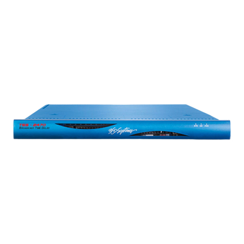
Micro control systems MCS-BACNET-ROUTER 2 Installation and operating manual

MCS Total
Solution
for all your
Control
Needs
5580 Enterprise Pkwy.
Fort Myers, FL 33905
Ofce: 239-694-0089
Fax: 239-694-0031
www.mcscontrols.com
MCS-BACNET-ROUTER 2
Installation & Reference Guide
Revision 2 - 11-30-2017

MCS-Bacnet-Router2 REVISION 2
2
The MCS Commitment is to provide practical solutions for the industries
needs and to be both a leader and partner in the effective use of microprocessor controls.
Micro Control Systems, Inc.
5580 Enterprise Parkway
Fort Myers, Florida 33905
PH:(239) 694-0089 FAX:(239) 694-0031
www.mcscontrols.com
All information contained within this document is considered to be proprietary information of Micro Control Systems, Inc.
No information or data from this document shall be published, used, reproduced, transmitted, or disclosed to others out-
side your organization without the prior expressed written consent of Micro Control Systems, Inc. This document and the
information contained herein shall be treated as proprietary. Reasonable provisions shall be provided to ensure that this
information remains proprietary by your employees, agents, and other personnel that may have access to this document.
Copyright ©2017
Date Author Description of Changes
2015--03-23 DEW Restructured manual
2016-11-17 DEW CHANGE DWG PAGE 3
2017-07-14 DEW Re-do Manual using Loytec quick start manual
2017-30-17 DEW Add UL and BTL logos - remove RoHS
Revision/Disclaimer Page

MCS-Bacnet-Router2 REVISION 2
3
Table of Contents
Chapter - 1. Introduction ..........................................................................................................................5
1.1. Overview.......................................................................................................................................................5
1.1.1 Scope..................................................................................................................................................5
Chapter - 2. Quick-Start Guide ..............................................................................................................6
2.1. Hardware Installation and IP Connection .....................................................................................................6
2.2. CongurationoftheMCS-BACNET-ROUTER2 ...........................................................................................6
2.3. MS/TP ProtocolAnalyzer..............................................................................................................................6
2.4. Reset to Factory Defaults.............................................................................................................................6
Chapter - 3. Hardware Installation ......................................................................................................7
3.1. Enclosure......................................................................................................................................................7
3.2. Product Label ...............................................................................................................................................7
3.3. Mounting.......................................................................................................................................................8
3.4. LED signals ..................................................................................................................................................8
3.4.1 Power LED..........................................................................................................................................8
3.4.2 Status LED..........................................................................................................................................8
3.4.3 MSTPActivity LED..............................................................................................................................8
3.4.4 Ethernet Link LED...............................................................................................................................8
3.4.5 Ethernet Activity LED..........................................................................................................................8
3.4.6 BACnet/IP LED ...................................................................................................................................8
3.4.7 BBMD LED..........................................................................................................................................9
3.5. Status Button................................................................................................................................................9
3.6. Wiring .........................................................................................................................................................10
Chapter - 4. Web Interface .....................................................................................................................11
4.1. Device Information and Account Management...........................................................................................11
4.2. Login and Passwords.................................................................................................................................12
4.3. DeviceConguration ..................................................................................................................................13
4.3.1 SystemConguration........................................................................................................................13
4.3.2 Backup and Restore..........................................................................................................................14
4.3.3 PortConguration.............................................................................................................................14
4.3.4 IPConguration ................................................................................................................................15
4.3.5 BACnetDeviceConguration ...........................................................................................................16
4.3.6 BACnet/IPConguration ...................................................................................................................16
4.3.7 MS/TPConguration.........................................................................................................................17

MCS-Bacnet-Router2 REVISION 2
4
Abbreviations
100BaseT............................100 Mbps Ethernet network with RJ-45 plug
ACL......................................Access Control List
BACne.................................Building Automation and Control Network
BBMD..................................BACnet Broadcast Management Device
BDT......................................Broadcast Distribution Table
B/IP. .....................................BACnet over IP (this is a BACnet data link layer)
DHCP ..................................DynamicHostCongurationProtocol
DNS.....................................Domain Name System
DST......................................Daylight Saving Time
FD........................................Foreign Device
FTP......................................File Transfer Protocol
GMT.....................................Greenwich Mean Time
IP......................................... Internet Protocol
MAC.....................................Media Access Control
MS/TP..................................Master/Slave Token Passing (this is a BACnet data link layer)
NAT......................................Network Address Translation
NTP......................................Network Time Protocol

MCS-Bacnet-Router2 REVISION 2
5
Chapter - 1. Introduction
1.1. Overview
TheMCS-BACNET-ROUTER2isaBTL-certiedBACnetrouterbetweenMS/TPandB/IP(BACnetoverIP)
as well as a BBMD (BACnet Broadcast Management Device) for transportation of BACnet broadcasts over
an IP network with several subnets.Additionally, it can serve as a BACnet time master and a BACnet MS/TP
slave proxy. The MCS-BACNET-ROUTER2 also provides additional features such as optional write protection of
the BDT, a BACnet/IP access control list and a simple BBMD communications test to troubleshoot the network.
The MS/TP port supports remote Wireshark packet capture for troubleshooting the MS/TP channel.
1.1.1 Scope
This document covers MCS-BACNET-ROUTER2 devices.
For additional information on the MCS-BACNET-ROUTER2 (LIP-ME201)
https://www.loytec.com/products/routers-nic/lip-bacnet

MCS-Bacnet-Router2 REVISION 2
6
Chapter - 2. Quick-Start Guide
This chapter provides the minimum list of steps necessary to setup the MCS-BACNET-ROUTER2
model MCS-BACNET-ROUTER2.
2.1. Hardware Installation and IP Connection
• Connect power, Ethernet, and MS/TP.
• ConnecttheConsole(Section8.2.1)andconguretheIPaddress,netmask,andgatewayor
connect to the MCS-BACNET-ROUTER2 over the Web interface right away and setup the IP
congurationthere.
• In both cases, reboot the MCS-BACNET-ROUTER2 to commit the new IP settings (use corre-
sponding menu item either in console menu or Web interface).
Important!
ThedefaultIPaddress192.168.1.254isonlysetforcongurationaccess.Itmustbechangedin
order to make the device functional.
2.2. Conguration of the MCS-BACNET-ROUTER2
• Connect to the MCS-BACNET-ROUTER2 using the new IP address in a Web browser.
• ClickonCongandenterthedefaultadministratorpassword'loytec4u'.Note,thatolderrmware
versions used 'admin' as the password.
• ClickonBACnetCongandsetuptheBACnetDeviceConguration).
• ClickonPortCongandsetuptheBACnet/IPandBACnetMS/TPportconguration
• If the MCS-BACNET-ROUTER2 should also act as a BBMD, click on BACnet BDT and setup the
Broadcast Distribution Table.
• Reboot the MCS-BACNET-ROUTER2 to commit the changes.
2.3. MS/TP Protocol Analyzer
The MCS-BACNET-ROUTER2 is equipped with a built-in MS/TP protocol capture facility. This facility can be
usedforofinelogging,whichstoresalogleonthedevice,oronlineremoteloggingwithWireshark.With
remote capture a Wireshark protocol analyzer on the PC can capture a live log of the MS/TP channel. For doing
so, the remote capture has to be enabled. See Section 8.3 for more details.
2.4. Reset to Factory Defaults
In case the password of the device has been forgotten you may need to reset the device back to factory
defaults to gain access again. On the MCS-BACNET-ROUTER2 press the service button and power-cycle the
device. Keep the button pressed until the port LEDs illuminate orange permanently. Release the button within
vesecondsfromthattimeontoresetthedevicetofactorydefaults.

MCS-Bacnet-Router2 REVISION 2
7
Chapter - 3. Hardware Installation
3.1. Enclosure
The MCS-BACNET-ROUTER2 enclosure is 107 mm wide for DIN rail mounting, following DIN 43 880
(see Figure 1).
3.2. Product Label
The product label on the side of the MCS-BACNET-ROUTER2 contains the following information
(see Figure 1):
• MCS-BACNET-ROUTER2 Order Number,
• Serial Number with bar-code (SER#),
• Ethernet MAC Address with bar-code (MAC1).
Unless stated otherwise, all bar codes are encoded using “Code 128”. An additional label is also supplied with
the MCS-BACNET-ROUTER2 for documentation purposes.
LIP-ME201 User Manual 10 LOYTEC
Version 4.8 LOYTEC electronics GmbH
3 Hardware Installation
3.1 Enclosure
The LIP-ME201 enclosure is 107 mm wide for DIN rail mounting, following DIN 43 880
(see Figure 1).
4 5 6
Status Button
and LED
105
off
on
1 2 3 45 6 7
DIP Switch
6
0
55
Serial Number
Order Number
85
Console
Connector Power
LED
BACnet Status
LEDs
Ethernet
100Base-T
Ethernet
MAC Address
11
15 16 17
Figure 1: LIP-ME201 Enclosure (dimensions in mm)
3.2 Product Label
The product label on the side of the LIP-ME201 contains the following information (see
Figure 1):

MCS-Bacnet-Router2 REVISION 2
8
3.3. Mounting
The device comes prepared for mounting on DIN rails following DIN 50 022. The device can be mounted in
anyposition.However,aninstallationplacewithproperairowmustbeselectedtoensurethattheMCS-
BACNET-ROUTER2’stemperaturedoesnotexceedthespeciedrange(seeChapter10).
3.4. LED signals
3.4.1 Power LED
The MCS-BACNET-ROUTER2 power LED lights up green when power is supplied to terminals 16 and 17.
3.4.2 Status LED
The MCS-BACNET-ROUTER2 is equipped with a red status LED (see Figure 1). This LED is normally off.
Ifthefall-backimageisexecuted,thestatusLEDashesredonceeverysecond.
3.4.3 MSTP Activity LED
The MS/TP port has a three-color MSTPActivity LED (see Figure 1). Table 1 shows the different LED patterns
oftheportandtheirmeaning.Apermanentcolorreectsastate.Flickerisfor25mswhenthereisactivityon
the MS/TP data link layer.
Behavior Description Comment
GREEN
permanently,
ickeroff
Multi-Master,tokenok,ickerwhentrafc Normal condition on a multi-
master MS/TP network.
ORANGEicker Solemaster,ickerwhentrafc Normal condition on a single-
master MS/TP network.
RED permanent,
ickerGREEN
Tokenloststate,ickerwhentransmit
attempt Cable might be broken.
REDashfast Transmission or receive errors This indicates bad cabling.
Table 1: MS/TPActivity LED Patterns
3.4.4 Ethernet Link LED
The Ethernet Link LED lights up green whenever an Ethernet cable is plugged-in and a physical connection
with a switch, hub, or PC can be established.
3.4.5 Ethernet Activity LED
The Ethernet Activity LED lights up green for 6 ms whenever a packet is transmitted or received or when a
collision is detected on the network cable.
3.4.6 BACnet/IP LED
TheBACnet/IPLEDashesgreenfor25mswhenBACnetpacketsaretransmittedorreceivedoverthe
BACnet/IP interface.

MCS-Bacnet-Router2 REVISION 2
9
3.4.7 BBMD LED
The BBMD LED is permanent green if BBMD is enabled. Otherwise, it is off.
3.5. Status Button
The MCS-BACNET-ROUTER2 is equipped with a status button (see Figure 1). When pressing the status
button shortly during normal operation of the MCS-BACNET-ROUTER2, it sends a BACnet “I-Am” message
on all active BACnet data link layers.
The status button can also be used to switch the device back to factory default state. Press the service button
and power-cycle the device. Keep the button pressed until the port LEDs illuminate orange permanently.
Releasethebuttonwithinvesecondsfromthattimeontoresetthedevicetofactorydefaults.Alternatively,
the device can be switched back to factory defaults over the console user interface.
1.1
DIP Switch Settings
The DIP switch assignment for the MCS-BACNET-ROUTER2 is shown in Table 2. Please leave all switches
at default state.
DIP Switch # Function Factory Default
1Must be OFF OFF
2Must be OFF OFF
3Must be ON ON
4Must be OFF OFF
5Must be OFF OFF
6Must be OFF OFF
7Must be OFF OFF
Table 2: DIP Switch Settings for MCS-BACNET-ROUTER2
1.2
Terminal Layout and Power Supply
The MCS-BACNET-ROUTER2 provides screw terminals to connect to the network as well as to the power
supply. The screw terminals can be used for wires of a maximum thickness of 1.5 mm2/AWG12. The device
can either be DC or AC powered.
Terminal Function
4BACnet MS/TP Ground
5BACnet MS/TP Non-Inverting Input
6BACnet MS/TP Inverting Input
8Ethernet 100BaseT
15 Earth Ground
16, 17 Power Supply 12-35 VDC or 12-24 VAC ± 10%
Do not connect terminal 17 to earth ground!
Table 3: MCS-BACNET-ROUTER2 Terminals

MCS-Bacnet-Router2 REVISION 2
10
3.6. Wiring
If BACnet over MS/TP is enabled, the MS/TP network segment must be properly terminated with an LT-04
network terminator connected at each of the two ends of the segment media.
Important:
When using 2-wire MS/TP, earth ground must be connected to both terminal 15 and 16 (see Figure 2a).
Never connect terminal 17 to earth ground!
LIP-ME201 User Manual 13 LOYTEC
Version 4.8 LOYTEC electronics GmbH
Terminal Function
4 BACnet MS/TP Ground
5 BACnet MS/TP Non-Inverting Input
6 BACnet MS/TP Inverting Input
8 Ethernet 100BaseT
15 Earth Ground
16, 17 Power Supply 12-35 VDC or 12-24 VAC ± 10%
Do not connect terminal 17 to earth ground!
Table 3: LIP-ME201 Terminals
3.8 Wiring
If BACnet over MS/TP is enabled, the MS/TP network segment must be properly
terminated with an LT-04 network terminator connected at each of the two ends of the
segment media.
Important: When using 2-wire MS/TP, earth ground must be connected to both terminal 15 and 16
(see Figure 2a). Never connect terminal 17 to earth ground!
2-wire
MS/TP
Power Supply
Ethernet
Ethernet
Power Supply3-wire
MS/TP
(a) (b)
Figure 2: Connecting the LIP-ME201: (a) 2-wire MS/TP, (b) 3-wire MS/TP

MCS-Bacnet-Router2 REVISION 2
11
Chapter - 4. Web Interface
TheMCS-BACNET-ROUTER2comeswithabuilt-inWebserverandaWebinterfacetoconguretheMCS-
BACNET-ROUTER2andextractstatisticsinformation.TheWebinterfaceallowsconguringtheIPsettings,
BACnetandothercongurationsettings.
4.1. Device Information and Account Management
In a Web browser, enter the default IP address 192.168.1.254 of the MCS-BACNET-ROUTER2. Note that if
your PC has an IP address in a subnet other than 192.168.1.xxx, you must open a command tool and enter
the following route command to add a route to device.
To Add a Route to the Device
1. Windows START 7Run
2. Enter ‘cmd’ and click OK.
3. In the command window enter the commandline
4. route add 192.168.1.254 %COMPUTERNAME%
5. In Windows7 replace %COMPUTERNAME% with the PC’s actual IP address.
6. Then open your Web browser and type in the default IP address ‘192.168.1.254’.
7. The device information page should appear as shown in Figure 3.
ThedeviceinformationpageshowsinformationabouttheMCS-BACNET-ROUTER2andthecurrentrmware
version. It also contains operational parameters, such as free memory, system temperature and supply voltage.
LIP-ME201 User Manual 15 LOYTEC
Version 4.8 LOYTEC electronics GmbH
Figure 3: Device Information Page.
The device information page shows information about the LIP-ME201 and the current
firmware version. It also contains operational parameters, such as free memory, system
temperature and supply voltage.
Click through the menus on the left hand side to become familiar with the different screens.
If you click on Config in the left menu, you will be asked to enter the administrator
password in order to make changes to the settings as shown in Figure 4. Enter the default
administrator password ‘loytec4u’ and select Login. Note, that previous firmware versions
used ‘admin’ as the default password.
Figure 4: Enter ‘loytec4u’ as the default administrator password.
The Config menu opens. Click on Passwords in the Config menu, which opens the
password configuration page as shown in Figure 5. The device has three user accounts: (1)
guest allows the user to view certain information only, e.g., the device info page. By
default the guest user has no password. (2) operator is able to read more sensible
information such as calendar data. (3) admin has full access to the device and can make
changes to its configuration. Note that the user accounts are also used to log on to the FTP
and Telnet server.

MCS-Bacnet-Router2 REVISION 2
12
4.2. Login and Passwords
Click through the menus on the left hand side to become familiar with the different screens. If you click on
Cong in the left menu, you will be asked to enter the administrator password in order to make changes to
the settings as shown in Figure 4. Enter the default administrator password ‘loytec4u’ and select Login. Note,
thatpreviousrmwareversionsused‘admin’asthedefaultpassword.
TheCongmenuopens.ClickonPasswords intheCongmenu,whichopensthepasswordconguration
page as shown in Figure 5. The device has three user accounts: (1) guest allows the user to view certain
information only, e.g., the device info page. By default the guest user has no password. (2) operator is able
to read more sensible information such as calendar data. (3) admin has full access to the device and can
makechangestoitsconguration.NotethattheuseraccountsarealsousedtologontotheFTPandTelnet
server.
Pleasechangetheadministratorpasswordinordertoprotectyourselffromunwantedcongurationchanges
by anyone else. To do so, select the admin account in the drop- down box and enter the new password.
If the administrator password is left empty, password protection is turned off and everyone can access the
MCS-BACNET-ROUTER2 without entering a password. Click on Change password to activate the change.
LIP-ME201 User Manual 15 LOYTEC
Version 4.8 LOYTEC electronics GmbH
Figure 3: Device Information Page.
The device information page shows information about the LIP-ME201 and the current
firmware version. It also contains operational parameters, such as free memory, system
temperature and supply voltage.
Click through the menus on the left hand side to become familiar with the different screens.
If you click on Config in the left menu, you will be asked to enter the administrator
password in order to make changes to the settings as shown in Figure 4. Enter the default
administrator password ‘loytec4u’ and select Login. Note, that previous firmware versions
used ‘admin’ as the default password.
Figure 4: Enter ‘loytec4u’ as the default administrator password.
The Config menu opens. Click on Passwords in the Config menu, which opens the
password configuration page as shown in Figure 5. The device has three user accounts: (1)
guest allows the user to view certain information only, e.g., the device info page. By
default the guest user has no password. (2) operator is able to read more sensible
information such as calendar data. (3) admin has full access to the device and can make
changes to its configuration. Note that the user accounts are also used to log on to the FTP
and Telnet server.
LIP-ME201 User Manual 16 LOYTEC
Version 4.8 LOYTEC electronics GmbH
Figure 5: Password Configuration Screen.
Please change the administrator password in order to protect yourself from unwanted
configuration changes by anyone else. To do so, select the admin account in the drop-
down box and enter the new password. If the administrator password is left empty,
password protection is turned off and everyone can access the LIP-ME201 without entering
a password. Click on Change password to activate the change.
4.2 Device Configuration
The device configuration pages allow viewing and changing the device settings of the LIP-
ME201. Here are some general rules for setting IP addresses, port numbers, and time
values:
•An empty IP address field disables the entry.
•An empty port number field sets the default port number.
•An empty time value field disables the time setting.
4.2.1 System Configuration
The system configuration page is shown in Figure 6. This page allows configuring the
device’s system time and other system settings. The TCP/IP Configuration link is a
shortcut to the Ethernet port configuration. Follow that link to change the IP settings of the
device.
The time sync source can be set to auto, manual, NTP, BACnet. In the auto mode, the
device switches to the first external time source that is discovered. Possible external time
sources are NTP, BACnet. The option manual allows setting the time manually in the
fields Local Time and Local Date. In manual mode, the device does not switch to an
external time source. Note, that if NTP is selected, the NTP servers have to be configured
on the IP Configuration page (see Section 4.2.4).
The time zone offset must be defined independently of the time source. It is specified as the
offset to GMT in hours and minutes (e.g., Vienna/Austria is +01:00, New York/USA is
-06:00). For setting the daylight saving time (DST) predefined choices are offered for
Europe and USA/Canada. DST can be switched off completely by choosing none or set
manually for other regions. In that case, start and end date of DST must be entered in the
fields below.

MCS-Bacnet-Router2 REVISION 2
13
4.3. Device Conguration
ThedevicecongurationpagesallowviewingandchangingthedevicesettingsoftheLIP-ME201.Hereare
some general rules for setting IP addresses, port numbers, and time values:
• AnemptyIPaddresselddisablestheentry.
• Anemptyportnumbereldsetsthedefaultportnumber.
• Anemptytimevalueelddisablesthetimesetting.
4.3.1 System Conguration
ThesystemcongurationpageisshowninFigure6.Thispageallowsconguringthedevice’ssystemtime
and other system settings. The TCP/IP Conguration linkisashortcuttotheEthernetportconguration.
Follow that link to change the IP settings of the device.
The time sync source can be set to auto, manual, NTP, BACnet. In the auto mode, the device switches
totherstexternaltimesourcethatisdiscovered.PossibleexternaltimesourcesareNTP,BACnet.Theoption
manual allowssettingthetimemanuallyintheeldsLocal Time and Local Date. In manual mode, the
device does not switch to an external time source. Note, that if NTP is selected, the NTP servers have to be
conguredontheIPCongurationpage(seeSection4.2.4).
Thetimezoneoffsetmustbedenedindependentlyofthetimesource.ItisspeciedastheoffsettoGMTin
hours and minutes (e.g., Vienna/Austria is +01:00, New York/USA is
-06:00).Forsettingthedaylightsavingtime(DST)predenedchoicesareofferedforEuropeandUSA/
Canada. DST can be switched off completely by choosing none or set manually for other regions. In that
case,startandenddateofDSTmustbeenteredintheeldsbelow.
Thenextsectiononthepageallowstocongurethedevice’searthposition.Thissettingdenesthelongitude,
latitude and elevation of the device. The latitude and longitude are entered as degrees, minutes, and seconds.
The altitude is entered in meters height above sea level. This setting is used for an astronomical clock.
Forxedlocationssuchasabuilding,thepositioncanbeenteredonthispage.
The CSV delimiter setting can be ignored on the MCS-BACNET-ROUTER2.
LIP-ME201 User Manual 17 LOYTEC
Version 4.8 LOYTEC electronics GmbH
Figure 6: System Configuration Page, e.g., for Vienna, Austria.
The next section on the page allows to configure the device’s earth position. This setting
defines the longitude, latitude and elevation of the device. The latitude and longitude are
entered as degrees, minutes, and seconds. The altitude is entered in meters height above sea
level. This setting is used for an astronomical clock. For fixed locations such as a building,
the position can be entered on this page.
The CSV delimiter setting can be ignored on the LIP-ME201.
4.2.2 Backup and Restore
A configuration backup of the LIP-ME201 device can be downloaded via the Web
interface. Click the backup link as shown in Figure 7 to start the download. The LIP-
ME201 device assembles a single file including all required files. A file requestor dialog
allows specifying the location where the backup file shall be stored.
To restore the device settings, simply select a previously generated backup file in the
Restore Configuration section of the page by clicking the button next to the Filename
field. Then press the Restore button.
The backed up configuration data consists of:
•Device settings (Passwords, IP settings, BDT, ACL, etc.),

MCS-Bacnet-Router2 REVISION 2
14
4.3.2 Backup and Restore
AcongurationbackupoftheMCS-BACNET-ROUTER2devicecanbedownloadedviatheWebinterface.
Click the backup link as shown in Figure 7 to start the download. The LIP- ME201 device assembles a single
leincludingallrequiredles.Alerequestordialogallowsspecifyingthelocationwherethebackupleshall
be stored.
Torestorethedevicesettings,simplyselectapreviouslygeneratedbackupleintheRestore Conguration
section of the page by clicking the button next to the Filename eld.ThenpresstheRestore button.
Thebackedupcongurationdataconsistsof:
• Device settings (Passwords, IP settings, BDT, ACL, etc.),
4.3.3 Port Conguration
Thismenuallowsconguringthedevice’scommunicationsports.Foreachcommunicationport,whichis
availableonthedeviceandshownonthelabel(e.g.,Port1,Port2,Ethernet),acorrespondingconguration
tab is provided by the Web UI.An example is shown in Figure 8. Each port tab contains a selection of available
communication protocols. By selecting a checkbox or radio button the various protocols can be enabled or
disabled on the communication port. Some ports allow exclusive protocol activation only, other ports (e.g., the
Ethernet port) allow multiple protocols bound to that port.
LIP-ME201 User Manual 18 LOYTEC
Version 4.8 LOYTEC electronics GmbH
Figure 7: Backup/Restore page.
4.2.3 Port Configuration
This menu allows configuring the device’s communications ports. For each communication
port, which is available on the device and shown on the label (e.g., Port 1, Port 2,
Ethernet), a corresponding configuration tab is provided by the Web UI. An example is
shown in Figure 8. Each port tab contains a selection of available communication
protocols. By selecting a checkbox or radio button the various protocols can be enabled or
disabled on the communication port. Some ports allow exclusive protocol activation only,
other ports (e.g., the Ethernet port) allow multiple protocols bound to that port.
Figure 8: Port Configuration Page.
When selecting a protocol on a communication port, the protocol’s communication
parameters are displayed in a box on the right-hand side. To save the settings of the
currently opened protocol, click the Save Settings button. Pressing Get Settings retrieves
the current settings from the device.
4.2.4 IP Configuration
The TCP/IP configuration is done under the Ethernet port tab as shown in Figure 9. The
mandatory IP settings, which are needed to operate the device, are marked with a red
asterisk (IP address, netmask, gateway). The Enable DHCP checkbox switches between
manual entry of the IP address, netmask, and gateway address, and automatic configuration
from a DHCP server.

MCS-Bacnet-Router2 REVISION 2
15
When selecting a protocol on a communication port, the protocol’s communication parameters are displayed
in a box on the right-hand side. To save the settings of the currently opened protocol, click the Save Settings
button. Pressing Get Settings retrieves the current settings from the device.
4.3.4 IP Conguration
TheTCP/IPcongurationisdoneundertheEthernetporttabasshowninFigure9.ThemandatoryIPsettings,
which are needed to operate the device, are marked with a red asterisk (IP address, netmask, gateway).
The Enable DHCP checkbox switches between manual entry of the IP address, netmask, and gateway
address,andautomaticcongurationfromaDHCPserver.
Hostname and Domainname areoptionalentriesandcanbeleftempty.ForsomeDHCPcongurationsit
maybenecessarytoenterahostname.PleasecontactyoursystemadministratoronhowtocongureDHCP
toacquireanIPaddress.Further,youcancongureupto3DomainNameServers.Currentlytheseentries
are not used.
ThedevicecomesconguredwithauniqueMACaddress.Thisaddresscanbechangedinordertoclonethe
MACaddressofanotherdevice.PleasecontactyoursystemadministratortoavoidMACaddressconicts.
ThedevicecanbeconguredtosynchronizeitsclockwithNTPtime.EntertheIPaddressofaprimaryand,
optionally, a secondary NTP server. The device will use NTP as a time source if the time sync source in the
systemcongurationpageissettoNTP (seeSection4.2.1).TheeldNTP status below the NTP server
settings displays the current NTP synchronization status (out-of-sync, or in-sync).
If the device is operated with a 10 Mbit/s-only hub, the link speed should be switched from Auto Detect to
10Mbps/Half-Duplex. With modern 100/10 Mbit/s switches, this setting can be left at its default.
Other standard protocols that are bound to the Ethernet interface are FTP, Telnet, and HTTP (Web server).
By deselecting the checkbox, those protocols can be individually disabled. The standard UDP/TCP ports can
be changed in the respective protocol settings. An example for the FTP server is shown for FTP in Figure 10.
TheFTPserverisusedforinstancetoupdatethermware(seeSection7.1).NotethatHTTPfortheWeb
servercanonlybedisabledontheconsoleinterfaceorbyusingthedevicecongurationoftheCongurator.
LIP-ME201 User Manual 19 LOYTEC
Version 4.8 LOYTEC electronics GmbH
Hostname and Domainname are optional entries and can be left empty. For some DHCP
configurations it may be necessary to enter a hostname. Please contact your system
administrator on how to configure DHCP to acquire an IP address. Further, you can
configure up to 3 Domain Name Servers. Currently these entries are not used.
Figure 9: IP Configuration Page.
The device comes configured with a unique MAC address. This address can be changed in
order to clone the MAC address of another device. Please contact your system
administrator to avoid MAC address conflicts.
The device can be configured to synchronize its clock with NTP time. Enter the IP address
of a primary and, optionally, a secondary NTP server. The device will use NTP as a time
source if the time sync source in the system configuration page is set to NTP (see Section
4.2.1). The field NTP status below the NTP server settings displays the current NTP
synchronization status (out-of-sync, or in-sync).
If the device is operated with a 10 Mbit/s-only hub, the link speed should be switched from
Auto Detect to 10Mbps/Half-Duplex. With modern 100/10 Mbit/s switches, this setting
can be left at its default.
Other standard protocols that are bound to the Ethernet interface are FTP, Telnet, and
HTTP (Web server). By deselecting the checkbox, those protocols can be individually
disabled. The standard UDP/TCP ports can be changed in the respective protocol settings.
An example for the FTP server is shown for FTP in Figure 10. The FTP server is used for
instance to update the firmware (see Section 7.1). Note that HTTP for the Web server can
only be disabled on the console interface or by using the device configuration of the
Configurator.

MCS-Bacnet-Router2 REVISION 2
16
4.3.5 BACnet Device Conguration
Figure11showstheBACnetdevicecongurationpage.ThiscongurationpageallowssettingtheDevice ID,
whichistheinstancepartoftheObject_IdentierpropertyoftheBACnetDeviceobject.TheeldDevice
name holds the name of the BACnet device object (property Object_Name).
Important:
The device ID and device name must be unique within the BACnet internetwork.
Further,thedescriptionandlocationcanbecongured.Thesecongurationitemscorrespondtotheproperties
Description, and Location respectively of the BACnet Device object. For tuning BACnet application timing
parameters, set APDU timeout, APDU segment timeout, and APDU retry count. The timeout values are
entered in seconds allowing decimal notation, e.g. "7.5".
OnthesettingsforBACnet/IPrefertoSection4.2.6.ForconguringtheMS/TPdatalinkreferto.
Note: If this page displays the message "Device communication is disabled via BACnet network!" the device has
been externally disabled. Reboot the device to activate communication again.
4.3.6 BACnet/IP Conguration
The BACnet/IP protocol is available on the Ethernet port. To enable BACnet/IP on the device, select the
BACnet/IPcheckboxontheEthernettaboftheportcongurationpage.
The BACnet/IP protocol settings are displayed in the settings box on the right-hand side as shown in Figure
12. The Network Number oftheBACnet/IPportmustbeconguredtooperatethebuilt-inrouter.Ifthe
LIP-ME201 User Manual 20 LOYTEC
Version 4.8 LOYTEC electronics GmbH
Figure 10: FTP server configuration on the Ethernet port.
4.2.5 BACnet Device Configuration
Figure 11 shows the BACnet device configuration page. This configuration page allows
setting the Device ID, which is the instance part of the Object_Identifier property of the
BACnet Device object. The field Device name holds the name of the BACnet device
object (property Object_Name).
Important: The device ID and device name must be unique within the BACnet internetwork.
Figure 11: BACnet Device Configuration.
Further, the description and location can be configured. These configuration items
correspond to the properties Description, and Location respectively of the BACnet Device
object. For tuning BACnet application timing parameters, set APDU timeout, APDU
segment timeout, and APDU retry count. The timeout values are entered in seconds
allowing decimal notation, e.g. "7.5".
On the settings for BACnet/IP refer to Section 4.2.6. For configuring the MS/TP data link
refer to Section 4.2.7.
Note: If this page displays the message "Device communication is disabled via BACnet network!"
the device has been externally disabled. Reboot the device to activate communication
again.
4.2.6 BACnet/IP Configuration
The BACnet/IP protocol is available on the Ethernet port. To enable BACnet/IP on the
device, select the BACnet/IP checkbox on the Ethernet tab of the port configuration page.
The BACnet/IP protocol settings are displayed in the settings box on the right-hand side as
shown in Figure 12. The Network Number of the BACnet/IP port must be configured to
operate the built-in router. If the BACnet/IP network uses a non-default UDP port number

MCS-Bacnet-Router2 REVISION 2
17
BACnet/IP network uses a non-default UDP port number other than 47808/0xBAC0, enter this port in the BACnet/
IP port eld. Enter ‘0’ in this eld for switching back to the default setting.
IntheeldBACnet/IP mode the operation mode of the device is selected:
• Device (Default): In this mode the device operates as a regular BACnet/IP device on the local
network without other advanced features.
• Foreign Device (FD): In this mode, the device registers at an existing BBMD in the BACnet/IP
network as a foreign device. It is used, if the device is located as a single BACnet/IP device on
a remote IP subnet or behind a NAT router. If operated as a foreign device behind a NAT router,
port forwarding to the BACnet/IP port (UDP, default port 0xBAC0) and optionally to the Web
server and FTP server port (TCP, default port 80 and 21) must be setup in the NAT router.
If foreign device is selected, the following, additional settings must bemade:
• FD BBMD IP address and FD BBMD port: IP address and port of the remote BBMD the device
registers at as a foreign device.
• FD re-registration: A foreign device must periodically re-register at a BBMD. Here you can setup
the corresponding interval. The default is 1800 seconds.
• FD retry timeout and FD retries: Here you can specify the behavior, if registration does not work
instantly. These values should be left at default: 30000ms / 3 retries.
• Broadcast Management Device (BBMD): Same as ‘Device’ but the BBMD function is enabled).
For BBMD-only function, MS/TP can also be disabled.
For debugging purposes, the BACnet/IP port can be disabled independently of the MS/TP port.
4.3.7 MS/TP Conguration
The BACnet MS/TP protocol can be enabled on the device’s port Port1. To enable it, click the BACnet MS/
LIP-ME201 User Manual 21 LOYTEC
Version 4.8 LOYTEC electronics GmbH
other than 47808/0xBAC0, enter this port in the BACnet/IP port field. Enter ‘0’ in this
field for switching back to the default setting.
Figure 12: BACnet/IP Configuration.
In the field BACnet/IP mode the operation mode of the device is selected:
•Device (Default): In this mode the device operates as a regular BACnet/IP device on
the local network without other advanced features.
•Foreign Device (FD): In this mode, the device registers at an existing BBMD in the
BACnet/IP network as a foreign device. It is used, if the device is located as a single
BACnet/IP device on a remote IP subnet or behind a NAT router. If operated as a
foreign device behind a NAT router, port forwarding to the BACnet/IP port (UDP,
default port 0xBAC0) and optionally to the Web server and FTP server port (TCP,
default port 80 and 21) must be setup in the NAT router. If foreign device is selected,
the following, additional settings must be made:
oFD BBMD IP address and FD BBMD port: IP address and port of the
remote BBMD the device registers at as a foreign device.
oFD re-registration: A foreign device must periodically re-register at a
BBMD. Here you can setup the corresponding interval. The default is 1800
seconds.
oFD retry timeout and FD retries: Here you can specify the behavior, if
registration does not work instantly. These values should be left at default:
30000ms / 3 retries.
•Broadcast Management Device (BBMD): Same as ‘Device’ but the BBMD function
is enabled (see Section 4.2.8). For BBMD-only function, MS/TP can also be disabled
(see Section 4.2.7).
For debugging purposes, the BACnet/IP port can be disabled independently of the MS/TP
port.
4.2.7 MS/TP Configuration
The BACnet MS/TP protocol can be enabled on the device’s port Port1. To enable it, click
the BACnet MS/TP radio button as shown in Figure 13. The MS/TP port on the LIP-
ME201 is enabled by default.
LIP-ME201 User Manual 22 LOYTEC
Version 4.8 LOYTEC electronics GmbH
Figure 13: MS/TP Configuration.
The MS/TP protocol settings are displayed in the settings box on the right-hand side as
shown in Figure 13. Mandatory settings are the MS/TP node number and the MS/TP
baud rate. The MS/TP node number determines the physical address of the device on the
MS/TP channel and must be in the range from ‘0’ to the number configured with the
MS/TP max master configuration option. It must be unique within the MS/TP channel.
The latter parameter defines the maximal number of MS/TP master devices on the MS/TP
channel. The Baud rate on the MS/TP channel can be set to 9600, 19200, 38400, and 76800
Baud.
Important: All masters on the MS/TP channel must have the same setting for MS/TP max master.
Decreasing the default value 127 of MS/TP max master may reduce latency on the
MS/TP bus.
It is strongly recommended to leave the MS/TP max info frames and the MS/TP max
master configuration options at their default settings. In any case the MS/TP max master
number must be high enough to include the highest MS/TP node number of all masters on
the channel. Slave devices may have a higher MS/TP node number than MS/TP max
master.
To operate with slow devices on the MS/TP network set the Network Timing option to
slow. This increases a number of timeouts, which is needed by some devices, but slows
down network communication. If communication problems occur in standard mode, try
setting the slow mode. For fine-tuning other parameters please refer to Section 6.1.
The Network Number of the MS/TP port must be set to a non-zero value in order to
operate the build-in BACnet/IP-BACnet MS/TP router
4.2.8 BACnet BDT (Broadcast Distribution Table)
The BBMD function is needed when a BACnet/IP network spans over several IP subnets
separated by IP routers. If the device is configured as a BBMD, i.e. the BACnet/IP mode is
set to Broadcast Management Device, see Section 4.2.6, the BDT (Broadcast Distribution
Table) specifies all other BBMDs of the BACnet/IP network. The BDT is shown in Figure
14.

MCS-Bacnet-Router2 REVISION 2
18
TP radio button as shown in Figure 13. The MS/TP port on the LIP- ME201 is enabled by default.The MS/TP
protocol settings are displayed in the settings box on the right-hand side as shown in Figure 13. Mandatory
settings are the MS/TP node number and the MS/TP baud rate. The MS/TP node number determines the
physicaladdressofthedeviceontheMS/TPchannelandmustbeintherangefrom‘0’tothenumbercongured
with the MS/TP max master congurationoption.ItmustbeuniquewithintheMS/TPchannel.Thelatter
parameterdenesthemaximalnumberofMS/TPmasterdevicesontheMS/TPchannel.TheBaudrateon
the MS/TP channel can be set to 9600, 19200, 38400, and 76800 Baud.
Important:
All masters on the MS/TP channel must have the same setting for MS/TP max master. Decreasing the
default value 127 of MS/TP max master may reduce latency on the MS/TP bus.
It is strongly recommended to leave the MS/TP max info frames and the MS/TP max master conguration
options at their default settings. In any case the MS/TP max master number must be high enough to include
the highest MS/TP node number of all masters on the channel. Slave devices may have a higher MS/TP node
number than MS/TP max master.
To operate with slow devices on the MS/TP network set the Network Timing option to slow. This increases a
number of timeouts, which is needed by some devices, but slows down network communication. If communication
problems occur in standard mode, try setting the slow mode.
The Network Number of the MS/TP port must be set to a non-zero value in order to operate the build-in
BACnet/IP-BACnet MS/TP router.
For additional information on the MCS-BACNET-ROUTER2 (LIP-ME201)
https://www.loytec.com/products/routers-nic/lip-bacnet

MCS-Bacnet-Router2 REVISION 2
19

Providing HVAC/R Control Solutions Worldwide
5580 Enterprise Pkwy. Fort Myers, FL 33905
Ofce: (239) 694-0089
Fax: (239) 694-0031
www.mcscontrols.com
Table of contents
Other Micro control systems Recording Equipment manuals
