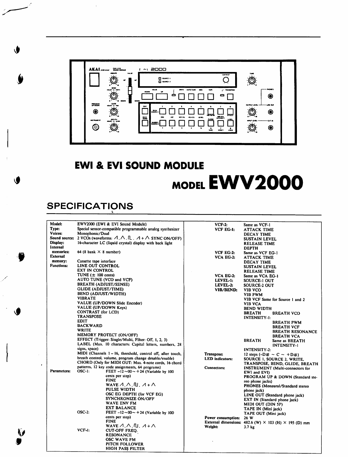
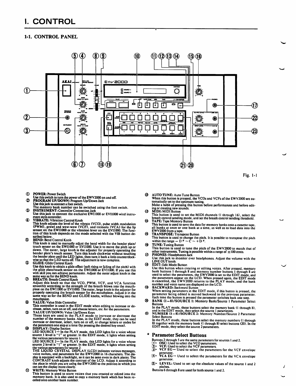
Akai EWV2000 User manual

EWI
&
EVI
SOUND
MODULE
MODEL
EWV2
III
SPECIFICATIONS
Scan by Manual Manor
http://www.markglinsky.com/ManualManor.html

I.
CONTROL
1-1.
CONTROL
PANEL
Fig.
1-1
(D
(D
<D
POWER:
Power
Switch
@
A
Use
this
switch
to
turn
the
power
of
the
EWV2000
on
and
off.
(2)
PROGRAM
UP/DOWN:
Program
Up/Down
Jack
Use
this
jack
to
connect
a
foot
switch.
The
memory
bank
number
can
be
switched
using
the
foot
switch.
($)
INSTRUMENT:
Controller
Connection
Jack
<Q>
Use
this
jack
to
connect
the exclusive
EWI
1000
or
EVI
1000
wind
instru
ment
style
controller.
<D
VIBRATE:
Vibration
Control
Knob
tg>
This
knob
adjusts
the
level
of
the
vibrato
(VCO),
pulse
width
modulation
(PWM),
growl
and
wow-wow
(VCF), and
tremolo
(VCA)
for
ihe
lip
sensor
on
the
EWI
1000
or
the
vibration
lever
on
the
EVI
1000.
The
func
tion
of
this
knob
depends
on
the
mode
selected
with
the
VIB
button
de-
©
scribed
below.
®
BEND:
Bend
Control
Knob
This
knob
is
used
lo
manually
adjust
the
bend
width
for
the
bender
plate/
(ft,
touch
sensor
on
the
EWI1000
or
EVI1000.
Use
it
to
move
the
pitch
up
or
down.
The
outer,
large
knob
is
the
adjuster
for
properly
operating
Ihe
bender
plate's
touch
sensor.
Turn
this
knob
clockwise
without
touching
ft)
the
bender
plate
until
the
LED
tights,
then
turn
it
back
a
little
counterclock-
wise
so
that
the
LED
turns
off.
The
adjustment
is
now
complete.
GLIDE:
Glide
Control
Knob
ft*
Use
this
knob
to
obtain
a
glide
effect
(soft
rising
or
falling
of
the
pitch)
with
the
glide
plate/touch
sensor
on
the
EWI
1000
or
EVI
1000.
If
you
use
this
with
skill
you
can
achieve
portamento.
Adjust
the
outer
adjust
knob
in
Ihe
same
way
as
for
the
BEND
knob.
BREATH:
Breath
Control
Knob
Adjust
this
knob
so
that
the
VCO,
PWM,
VCF,
and
VCA
function
smoothly
according
to
the
strength
of
the
breath
blown
into
the
mouth-
(\i>
piece
on
the
EWI1000
or
EVI
1000.
The
outer,
large
knob
is
the
adjuster
for
properly
operating
the
breath
sensor
for
the
mouthpiece.
Adjust
il
in
the
same
way
as
for
the
BEND
and
GLIDE
knobs,
without
blowing
into
Ihe
mouthpiece.
&,,
(!)
VALUE:
Value
Slide
Controller
^
This
controller
is
used
in
the
EDIT
mode
when
editing
lo
increase
or
de
crease,
select,
turn
on
or
off,
and
choose
letters,
etc.
for
the
parameters.
<D
VALUE
UP/DOWN:
Value
Up/Down
Keys
<8)
These
keys
are
used
in
the
PLAY
mode
to
increase
or
decrease
the
number
of
the
memory
banks.
Also,
in
the
EDIT
mode,
they
can
be
used
increase
or
decrease,
select,
turn
on
or
off,
or
change
tellers
or
codes
for
ihe
parameters
one
step
at
a
time
(by
pressing
the
desired
key
once).
©
DISPLAY:
Display
Section
LED
SOURCE
1
—
In
the
PLAY
mode,
this
LED
lights
for
a
voice
whose
source
I
level
is
"I"
or
greater.
In
the
EDIT
mode,
it
lights
when
setting
the
various
parameters
for
source
I.
LED
SOURCE
2—
In
the
PLAY
mode,
this
LED
lights
for
a
voice
whose
source
2
level
is
"1"
or
greater.
In
the
EDIT
mode,
it
lights
when
setting
the
various
parameters
for
source
2.
THE
LIQUID
CRYSTAL
DISPLAY
(LCD)
indicates
various
messages,
voice
names,
and
parameters
for
the
EWV2000
in
16
characters.
The
dis
play
is
equipped
with
a
backlight,
so
it
can
be
seen
even
in
dark
places.
The
CONTRAST
knob
adjusts
the
contrast
of
the
LCD.
Adjust
it
according
to
Ihe
place
in
which
you
are
using
the
EWV2000
to
the
position
in
which
you
can
see
the
display
more
clearly.
(Q)
WRITE:
Memory
Write
Button
This
button
is
used
to
store
voices
thai
you
created
or
edited
into
the
memory
bank.
Il
is
also
used
lo
copy
a
memory
bank
which
has
been
re
called
onto
another
bank
number.
AUTOTUNE:
Auto
Tune
Button
When
this
button
is
pressed,
the
VCOs
and
VCFs
of
the
EWV2000
are
au
tomatically
set
to
the
optimum
tuning.
Make
a
habit
of
pressing
this
button
before
performances
and
before
edit
ing
or
creating
new
sounds.
MIDI:
MIDI
Button
This
button
is
used
to
set
the
MIDI
channels
(1
through
16),
select
the
breath
control
sending
mode,
and
set
the
breath
control
sending
threshold.
TAPE:
Tape
Memory
Button
This
button
is
used
to
save
the
data
for
memory
banks
onto
a
cassette
tape,
all
banks
at
once
or
one
bank
at
a
lime,
as
well
as
to
load data
into
the
EWV2000fromatape.
TRANSPOSE:
Transpose
Button
This
button
is
used
to
change
the
pilch.
It
is
possible
to
transpose the
pitch
within the
range
—
D"—C--+D#.
TUNE:
Tuning
Button
This
button
is
used
lo
tune
the
pitch
of
the
EWV2000
to
match
that
of
other
instruments.
Tuning
is
possible
within
a
range
of
±
100
cents.
PHONES:
Headphones
Jack
Use
this
jack
to
monitor over
headphones.
Adjust
ihe
volume
with
the
LINE
OUT
knob.
EDIT:
Edit
Mode
Button
Use
this
button
when
creating
or
editing
voices.
After
pressed,
memory
bank
buttons
I
through
8
and
memory
number
buttons
I
through
8
arc
used
lo
select
ihe
parameters,
the
EWV2000
is
set
to
the
EDIT
mode,
and
the
parameters
appear
on
the
LCD.
When
pressed
again,
the
EDIT
mode
is
cancelled,
the
EWV2000
returns
to
the
PLAY
mode,
and
the
bank
number
and
voice
name
are
displayed
on
the
LCD.
BACKWARD:
Backward
Button
When
selling
parameters
in
the
EDIT
mode,
if
this
button
is
pressed,
the
parameter
being
edited
is
moved
backward
to
the
previous parameter.
Each
time
the
button
is
pressed
the
parameter
switches
back
one
step.
BANK
(l-8)/SOURCE
I:
Memory
Bank/Source
I
Parameter
Select
Buttons
In
the
PLAY
mode,
these
buttons
select
the
memory
bank
(I
through
8),
and
in
Ihe
EDIT
mode,
they
select
the
source
1
parameters.
NUMBER
(l-8)/SOURCE
2:
Memory
Number/Source
2
Parameter
Select
Buttons
In
Ihe
PLAY
mode,
these
buttons
select
the
memory
numbers
(I
through
8)
together
with
the
memory
bank
(1
through
8)
select
buttons
(20).
In
the
EDIT
mode,
they
select
the
source
2
parameters.
Parameter
Select
Buttons
Buttons
2
through
S
are
the
same
parameters
for
sources
I
and
2.
LH-
OSC:
Used
lo
scieel
the
VCO
parameters.
3h
VCF:
Used
lo
select
ihe
VCF
parameters.
[J]~
VCF
EG—
Used
lo
select
the
parameters
for
the
VCF
envelope
generator.
3]-
VCA
EG--
Used
lo
select
the
parameters
for
the
VCA
envelope
generator.
[S-
LEVEL:
Used
to
set
up
ihe absolute
values
of
the
source
I
and
2
pitches.
Buttons
6
through
8
are
used
for
both
source
1
and
2.
Scan by Manual Manor
http://www.markglinsky.com/ManualManor.html

IS-
VIB/BEND:
With
this
button,
the
vibrato
(VCO),
PWM,
growl
(VCF),
and
tremolo
(VCA)
effects
can
be
set
for
each
voice.
Also,
(he
bend
width
for
each
voice
can
be
set
within
a
maximum
range
of
±700
cents.
CHORD:
This
is
a
special
function
which
makes
it
possible
to
play
an
external
MIDI
compatible
sound
source
in
polyphonic.
SAVE:
Used
to
save
voice
data
onto
a
tape.
Qh
BREATH
INTENSITY:
With
this
button,
the
breath
sensor
effect
can
be
set for
each
voice.
VERIFY:
Used
to
check
whether
data
has
been
properly
saved
onto
a
tape,
fj}-
EFFECT:
This
button
contains
modes
for
selecting
the
trigger
(sin-
gle/multi)
for
triggering
the
envelope
generator
and
one
of
the
three
fitters
for
processing
voices.
LABEL:
Used
to
give
names
or
labels
to
voices
you
have
created.
LOAD:
Used
to
load
data
which
has
been
saved
onto
a
tape.
LINE
OUT:
Line
Output
Jack
and
Output
Level
Knob
The
output
jack
is
a
06.3mm
standard
phone
plug
jack.
Connect
it
to
the
line
input
jack
on
a
mixer
or
amplifier.
Usually
set
the
output
level
knob
between
the
8
and
10
position.
EXT
IN:
External
Sound
Source
Input
Jack
and
Input
Level
Knob
The
input
jack
is
a
(£6.3
mm
standard
phone
plug
jack.
Connect
it
to
the
line
output
jack
on
an
external
synthesizer
or
digital
sam
pler.
EXT
IN
is
used
with
source
1.
Usually
set
the
input
level
knob
be
tween
the
center
and
the
10
position,
and
adjust
the
output
level
of
the
syn
thesizer
or
digital
sampler
so
that
the
sound
is
input
with
no
distortion.
adjust
the
output
level
of
the
synthesizer
or
digital
sampler
so
that
the
sound
is
input
with
no
distortion.
1-2.
REAR
PANEL
\KUIIK
IIIK
( 4
©
LT3
AKAI
professional
Fig.
1-2
(D
TAPE
IN/OUT:
Cassette
Tape
Recorder
Input/Output
Jacks
Use
these
jacks
when
saving
or
loading
voice
data
onto
or
from
a
cassette
tape.
Connect
with
mini
plug
cords.
(D
MEMORY
PROTECT:
Memory
Protect
Switch
This
switch
is
used
to
protect
the
memory
banks.
Set
to
OFF
when
writing
voice
data,
or
when
loading
or
verifying
data
on
a
tape.
Oth
erwise,
keep
in
the
ON
position.
(D
MIDI
OUT:
MIDI
Output
Terminal
Use
this
terminal
when
you
want
to
control
another
MIDI
compo
nent
(synthesizer
or
keyboard)
or
a
MIDI
sampler
with
the
EWIlOOOorEVMOOO.
®
POWER
INLET:
Power
Inlet
Only
use
the
included
power
cord.
Scan by Manual Manor
http://www.markglinsky.com/ManualManor.html

II.
DISMANTLING
OF
UNIT
In
case
of
trouble,
etc,
necessitating
dismantling,
please
dismantle
in
the
order
shown
in
the
photographs.
Reassemble
in
reverse
order.
FRONT
PANEL
III.
PRINCIPAL
PARTS
LOCATIONS
PLAT
Fig.
2-1
VR
I
VIBRATE
CONTROL
ADJ.
OPERATION(B)
PCB
LI0I9A502B
POWER
SWITCH
f
SW
I
I
OPERATION(D)
PCB
LIOI9A5O2D
CONNECTOR
OPERATION(C)
PCB
LI0I9A502C
STRING
8
BASSOON
VCA
peg
u...,
_._
FILTER
PCB
MAIN
PCB
LI0I9A5030
LI0I9C5040
LIOI9A5OIA
POWER
TRANS
(T90I)
LJ0I9
Q]
LI0I9
fC~Al
LI0I9
E.V.B
VOLTAGE
SELECT
SWITCH
SW90I
\
*
Fi
Scan by Manual Manor
http://www.markglinsky.com/ManualManor.html

IV.
MIDI
IMPLEMENTATION
CHART
[EWI
&
EVI-SOUND
MODULE]
MODEL
EWV2000
Date:
7/9,
1987
MIDI
Implementation
Chart
Version:
1.0
Mode
1:
OMNI
ON,
POLY
Mode
V.
OMNT
OFF.
POT
Y
O-
Scan by Manual Manor
http://www.markglinsky.com/ManualManor.html

V.
ADJUSTMENT
5-1.
LOCATION
OF
ADJUSTMENT
VALUEM
a.
ADJUSTMENT
OF
VIBRATION
CONTROL
AMPLIFIER
OPERATION(A)
PCB
b.
ADJUSTMENT
OF
STRING
&
BASSOON
FILTER
PCB
FRONT
Fig. 5-1
STRING
8
BASSOON
FILTER
PCB
FRONT
Fig.
5-2
5-2.
MODEL
EWV2000
ADJUSTMENT
PROCEDURE
A.
ADJUSTMENT
OF
VIBRATE
CONTROL
AMPLIFIER
1)
Connect
the
EWI1000
to
the
EWV2000.
Connect
an
oscilloscope
to
the
line
outputs,
and
set
the
output
level
control
to
maximum.
2)
Turn
EWV20O0
power
ON.
[Pll
JUDD]
will
be
displayed
on
the
LCD.
3)
Press
the
EDIT
key,
then
press
the
source
1
"LEVEL"
parameter
selector
key
and
select
|QSC
LEVEL
1001.
4)
Use
the
1
VALUE
SLIDE
CONTROLLER
|
to
set
the
indication
to
|
OSC
LEVElTOOl
then
adjust
so
that
only
source
2.
Sawtooth
wave
(/I/I/I/I)
is
sent
out
through
the
output
terminals.
5)
Turn
the
"BREATH
ADJUST"
knob.
The
LED
will
light,
and
the
sawtooth
waveform
will
be
displayed
on
the
oscilloscope
screen
(refer
to
fig.
5-3).
6)
Set
the
VIBRATE
CONTROL
knob
to
maximum,
and
output
C,
from
the
EWI1000.
7)
Press
the
"VIB/BEND"
parameter
selector
key
and
select
|
VIB
VCO
10~|.
8)
Adjust
the
OPERATION
(A)
PCB
VRI
so
that
tone
is
not
altered
when
changing
"VIB
VCO"
from
00
to
100
with
the
"VAT
UE
SLTDF
CONTROT.T
FR
Scan by Manual Manor
http://www.markglinsky.com/ManualManor.html

B.
ADJUSTMENT
OF
STRING
&
BASSOON
FILTER.
"
1)
Connect
the
EWIIOOO
to
the
EWV2000.
Connect
an
oscilloscope
to
the
LINE
OUT
terminal,
and
set
the
output
level
control
to
maximum.
2)
Follow
steps
2
to 5
of
the
ADJUSTMENT
OF
VIBRATE
CONTROL
AMPLIFIER
section.
3)
Without
touching
the
EWIIOOO
touch
sensor,
confirm
that
the
sawtooth
waveform
shown
in
fig.
5-3
is
output.
Fig.
5-3
4)
Display
[FILTER
OFF]
on
the
LCD
using
the
EFFECT
key,
then
press
the
"VALUE
UP"
key
and
select
[FILTER
1].
5)
Adjust
the
STRING
&
BASSOON
FILTER
PCB
VR1
so
as
to
obtain
the
waveform
in
fig.
5-4.
Fig.
5-4
6)
Press
the
"VALUE
UP"
key
again,
and
select
[FILTER
2.]
7)
Turn
the
STRING
&
BASSOON
FILTER
PCB
VR2
AND
VR4
fully
clockwise,
and
VR3
fully
counterclockwise.
8)
While
looking
at
the
oscilloscope,
adjust
VR2
so
as to
obtain
maximum
oscillation
frequency.
*
Take
care
not
to
turn
VR2
excessively,
otherwise
oscillation
may
stop.
(fig.
5-5,
5-6).
5*5
Fig.
5-6
9)
Turn
VR3
to
stop
oscillation,
then
adjust
it
so
as
to
obtain
the
waveform
in
fig.
5-7.
Fig.
5-7
10)
Output
C,
from
the
EW1000,
then
adjust
VR4
so
as
to
obtain
the
waveform
in
fig.
5-8.
v*
Fig.
5-8
Scan by Manual Manor
http://www.markglinsky.com/ManualManor.html

VI.
PARTS
LIST
ATTENTION
1.
When
placing
an
order*f<jr
parts,
be
sure
to
list
Part
No.,
Model
No. and
the
description
of
each
part.
Otherwise,
the
non-delivery
of
the
part
or
the
delivery
of a
wrong
part
may
result.
2.
Please
make
sure that Part
No.
is
correct
when
ordering.
If
not,
a
part
different
from
the
one
you
ordered
may
be
delivered.
3.
Since
the
parts
shown
in
Parts
list
of
Preliminary
Service
Manual
may
have
been
the
subject
of
changes,
please
use
this
Parts
List
for
all
future
reference.
HOW
TO
USE
THIS
PARTS
LIST
1.
This
Parts
List
lists
those
parts
which
are
considered
necessary
for
repairs.
Other
common
parts,
such
as
resistors
and
capacitors,
are
listed
in
the
"Common
List
for
Service
Parts"
from
which
these
parts
should
be
selected
and
stocked.
2.
The
Recommended
Spare
Parts
List
shows
those
parts
in
the
Parts
List
which
are
considered
particularly
important
for
service.
3.
Parts
not
shown
in
the
Parts
List
and
"Common
List
for
Service
Parts"
will
not
in
principle
be
supplied.
4.
How
to
read
the
Parts
List.
a)
Mechanism
Block
b)
PC
Board
2.
HEAD
BASE
BLOCK
6.
MAIN
PC
BOARD
REF.
NO.
PART
NO.
BH-T2023A320A
HP-H2206A010A
ZS-477876
ZS-S36488
ZG-402895
DESCRIPTION
HEAD
BASE
BLOCK
HEAD
R/P
PR4-8FU
C
PAN20X03STL
CMT
BID2OXO8STL
CMT
SP
CS
ANGLE
ADJUST
SP
(Service
Parts)
Classification
A
small
"x"
indicates
that
this
part
is
not
shown
in
the
Photo
or
Illustration.
This
number
corresponds
with
the
indi
vidual
parts
index
number
in
that
figure.
This
number
corresponds
with
the
Figure-
Number.
Symbols
for
primary
destination—'
IA]:AAL(U.S.A.)
[S]:SAA
(Australia)
[B]:
BEAB(England)
[U]:
U/T(Universal
Area)
[C]:
CS
A
(Canada)
[V]:
VDE(W.
Germany)
[E]:
CEE(Europe)
[Y]:
Custom
Version
[J):JPN(
Japan)
'
SP
(Service
Parts)
Classification
—These
reference
symbols
correspond
with
component
symbols
in
the
Schematic
Diagrams.
The
available
PC
Board
Blocks
are
listed
separately.
5.
When
Part
No.
is
known,
Parts
Index
at
end
of
Parts
List
can
be
used
to
locate
where
that
part
is
shown
in
Parts
List
by
its
Reference
No.
listed
at
right
of
Part
No.
s-/
WARNING
A
(*)
INDICATES
SAFETY
CRITICAL
COMPONENTS.
FOR
CONTINUED
SAFETY,
REPLACE
SAFETY
CRITICAL
COMPONENTS
ONLY
WITH
MANUFACTURE'S
RECOMMENDED
PARTS.
AVERTISSEMENT
A
(*)
IL
INDIQUE
LES
COMPOSANTS
CRITIQUES
DE
SECURITE.
POUR
MADMTENIR
LE
DEGRE
DE
SECURITE
DE
L'APPAREBL,
NE
REMPLACER
QUE
DES
PIECES
RECOMMANDEES
PAR
LE
FABRICANT.
Scan by Manual Manor
http://www.markglinsky.com/ManualManor.html

1.
RECOMMENDED
SPARE
PARTS
Ref.
No.
Part
No.
*BT-3754OO
.M
e
9
10
11
12
13
14
15
16
17
18
19
20
21
22
23
24
25
26
27
28
29
30
31
32
33
34
35
36
37
38
39
40
41
42
43
44
45
46
47
48
49
50
51
52
53
54
55
56
57
58
♦BT-375408
*BT-375399
EC-368716
EC-368719
ED-359S63
ED-364261
ED-376335
*ED-357036
*ED-357038
ED-301911
ED-3442B0
ED-329058
*EF-355385
♦EF-359342
*EF-355374
*EF-695766
+EF-6
68474
*EF-593706
*EF-327103
*EF-306124
*EF-309388
*EF-305703
*EF-309391
EI-364246
EI-360045
EI-365872
EI-360954
EI-375437
EI-379482
EI-375347
EI-375345
EI-375439
EI-356160
EI-349719
*EI-348123
♦EI-359552
EI-362588
EI-364275
EI-355910
EI-364247
EI-336995
*EI-375441
♦EI-375442
EI-364253
EI-376178
EI-310036
EI-356049
EI-379539J2
EI-375438
EI-371671
EI-354123
EO-318365
EQ-348929
*ER-326169
*ER-359268
*ER-359269
♦ER-375473
Description
TRANS
P0WL1019IC.A)
[CA.Y1]
TRANS
P0WL1019(E,V.B.S)
[E.V.B.S]
TRANS
POWL1019(J)
[J]
C
EC
V
CUT
SR-AKY
102M
25.0DC
C
EC
V
CUT
SR-TIK
472M
16.0DC
D
LED
LN81CV-(LF)
AK
ORANGE
[TRANS]
DLEDSLP-981C-50
[SOURCE
2]
D
SCHOTTKY
SB02-03S-T
0
SILICON
0BA20B
100/2.0A
D
SILICON
DEB
1CB
100/1.0A
0
SILICON
H
OS448
D
SILICON
HGMA-O1-FY2FO5
D
ZENER
H
HZ5
C1
FUSE
BET
T
250V
315MA
(B)
FUSE
BET
T
250V
400MA
[B]
FUSE
BET
T
250V
500MA
[B]
FUSE
SEMKOT
250V
315MA
[E.V.S]
FUSE
SEMKO
T
250V
400MA
[E.V.S]
FUSE
SEMKO
T
250V
500MA
[E.V.S]
FUSE
TSC
A
250V
500MA
[J]
FUSE
TSC
A
250V
630MA
[J]
FUSE
TSC
A
250V
800MA
[J]
FUSE
TSC
125V
630MA
[A.C.Y1]
FUSE
TSC
125V
800MA
[A.C.Y1]
IC
CEM3394
ICDG211CJ
IC
EHK-MD6207
ICIR9311
ICLC3664NL-10
ICLM1458N
ICMM74HC14N
IC
MM74KC373N
IC
M5206P
ICM5216P
ICM5218P
IC
M5230L
IC
M5236L
IC
M5238P
IC
M74LS05N
IC
M74LS42P
ICNJM13600
IC
NJM78L05A
ICNJM78M12A
ICNJM79M12A
IC
PST520D-2
IC
SSM2300
IC
TC4086BP
ICTC74HC139P
IC
TMM27128AD-20
EWV2000-V1.2
IC
TMP82C55AP-2
ICUPD78C11G-044-36
OSC
CE
CSA120MT
12.000000MHZ
COIL
FIX
1LAL04
102K
RELAY
SIG
G5A-237P
2TR
12V
R
FUSE
H
S10
ERD2FC
1/4W
22R0G
R0MFHS12FS
1W
181J
ROMFHS12FS1W221J
R0MFHS12FS1W911J
Ref.
No. Part No.
59
60
61
62
63
64
65
66
67
68
69
70
71
72
73
74
75
76
77
78
♦ER-321619
*ES-373020
ES-306430
ES-364255
ES-349474
ET-375780
♦
ET-375446
ET-355689
ET-360067
ET-349592
*ET-369572
EV-356582
EV-378372
EV-378373
EV-336770
EV-375452
EV-375453
EV-375455
EV-365876
EZ-358816
Description
R0MFHS15FS
1W101J
SW
PUSH
ESB-8283V
[POWER
SW]
SW
SLIDE
J-S4013#01
01-2
[E.V.B.S]
SW
SLIDE
SSP322
SWTACTSKHHAM004A
[NUMBER
1]
TR
FET
2SK381
E
F05
TR2SB1142
T.U
TR2SC3246G.H.JF05
TR 2SC3330
T.U
F05
TR
2SC3400
F05
TR2SD1682T.U
R
S-FIX
HRHO615CO.1OW
473
R
S-FIX
H
RK0651C
0.05W
104
R
S-FIX
H
RH0651C
0.05
W
105
R
S-FIX
H
RK0651C
0.05W
473
VR
ROTARY
EVJ-1KA
103
[VIBRATE]
VR
ROTARY
EVJ-1KA
202
[CONTRAST]
VR
ROTARY
EWJ-CGA
16P
103/503
[BREATH.SENSE]
VR
SLIDE
VJ4513-2PVNB5
103
[VALUE)
BATTERY
LITHIUM
BR2032-1HF
2.
P.C
BOARD
BLOCK
Ref.
No.
Part
No.
BA-L1O19AO2OA
BA-L1019A030A
BA-L1O19AO5OA
BA-L1019A060A
Description
PC(#|
MAIN
BLK
EWV2000
PC(#>
OPERATION
BLK
EWV2000
PC
STIN
FILTER
BLK
EWV2000
PC
VCA
BLK
3.
MAIN
A
P.C
BOARD
Ref.
No.
Part
No.
BT1
C90
C94
C95
D1
D2
D3
D4
D5
D7
D8
D9
D10
D11
D12
D13
D14
D15
D16
D17
D18
D19
D20
D21
D22
EZ-358816
EC-368719
EC-368716
EC-368716
ED-3442B0
ED-344280
ED-344280
ED-344280
ED-344280
ED-344280
ED-344280
ED-344280
ED-344280
ED-344280
ED-344280
ED-344280
ED-344280
ED-344280
ED-344280
ED-344280
ED-344280
*ED-357036
*ED-357038
ED-344280
ED-344280
Description
BATTERY
LITHIUM
BR2032-1HF
C
EC
V CUT
SR-TK
472M
16.0DC
C
EC
V
CUT
SR-AKY
102M
25.0DC
C
EC
V CUT
SR-AKY
102M
25.0DC
D
SILICON
HGMA-01-FY2F05
D
SIUCON
H
GMA-01-FY2
F05
D
SILICON
HGMA-01-FY2F05
D
SILICON
H
GMA-01-FY2
F05
D
SILICON
H
GMA-01
-FY2
F05
D
SILICON
H
GMA-01
-FY2
F05
D
SILICON
H
GMA-01
-FY2
F05
D
SILICON
H
GMA-01
-FY2
FO5
D
SILICON
H
GMA-01-FY2
F05
D
SIUCON
H
GMA-01-FY2F05
D
SILICON
H
GMA-01
-FY2
F05
D
SIUCON
H
GMA-01
-FY2
F05
D
SILICON
H
GMA-01-FY2F0S
D
SILICON
H
GMA-01
-FY2
F05
D
SILICON
H
GMA-01-FY2
FO5
D
SILICON
H
GMA-01
-FY2
F05
D
SILICON
H
GMA-01
-FY2
F05
D
SILICON
DBA20B
100/2.0A
D
SILICON
DBB10B
100/1.OA
0
SILICON
H
GMA-01-FY2FO5
D
SILICON
H
GMA-01
-FY2
FO5
Scan by Manual Manor
http://www.markglinsky.com/ManualManor.html

Scan by Manual Manor
http://www.markglinsky.com/ManualManor.html

t
7.
OPERATION
B
P.C
BOARD
Ref.
No.
Part
No.
D1
IC1
J1
J2
J3
RL1
R7
R8
ED-301911
EI-356160
EJ-353031
EJ-354105
EJ-354105
EQ-34B929
*ER-321619
*ER-321619
Description
D
SILICON
H
DS448
ICM5216P
PHONE
J3PHLJ0520-010
[PHONE]
PHONE
J2PHLJ0520-110
6.3
(LINE
OUT]
PHONE
J2PHLJ0520-110
6.3
[EXT
IN]
RELAY
SIG
G5A-237P
2TR
12V
R0MFHS15FS
1W
101J
R0MFHS15FS1W101J
8.
OPERATION
C
P.C
BOARD
Ref.
No.
Part
No.
Description
IC1
EI-349719
ICM5218P
VR1
EV-375455
VR
ROTARY
EWJ-CGA
16P
103/503
[BREATH.SENSE]
VR2
EV-375455
VR
ROTARY
EWJ-CGA
16P
103/503
[BENO.WIDTH]
VR3
EV-375455
VR
ROTARY
EWJ-CGA
16P
103/503
[GUDE.TIME]
9.
OPERATION
D
P.C
BOARD
Ref.
No.
Part
No.
Description
J1
EJ-379523
PHONE
J
3P
HLJ4305-3080
SJJUT
[PRG
UP.O0WN]
Scan by Manual Manor
http://www.markglinsky.com/ManualManor.html

10.
OPERATION
E P.C
BOARD
Ref.
No. Part
No.
VR1
EV-375453
Description
VR
ROTARY
EVJ-1KA
202
[CONTRAST]
11.
STRING
AND
BASSOON
FILTER
P.C
BOARD
12.
VCA
P.C
BOARD
Ref.
No.
IC1
IC2
IC3
R1
R2
13.
FINAL
ASSEMBLY
BLOCK
No*
Scan by Manual Manor
http://www.markglinsky.com/ManualManor.html

Q
M
/--$
xooia
Aiawassv
ivnm
Scan by Manual Manor
http://www.markglinsky.com/ManualManor.html

INDEX
Scan by Manual Manor
http://www.markglinsky.com/ManualManor.html

Part
No.
Ref.
No.
Part
No.
Ref.
No.
Part
No.
Ref.
No.
Part
No.
Ref.
No.
iky
Scan by Manual Manor
http://www.markglinsky.com/ManualManor.html

'ERATION(B)
TO
STRI
KRSR
IONIAI
TO
OPERATION
Al
TO
OPERATION
(A)
PCB
<J5)
PCD
IJ4)
TO
OPERATION
(AI
PCB
(J2)
TO
OPERATION
(Al
PCB
(Jl)
bkbkk
a
z
5
<
o
o
o
■s
CBS
33O/6.3IMI
VJt
10/16
(M)
C3fl
IOOP
II
°T
S2
So
So
33
sl;
?
!
s
s
5
s
5
u
s
i
s
-M-
frnmn
Scan by Manual Manor
http://www.markglinsky.com/ManualManor.html

—
o
"
oiai
Hi
V5019iWrN
9231
ZDI
S0
9
31
H

TO STRING
B
TO
POWER
TRANSFORMER
BASS$Jjj
(^LTER T°
CO
o
CD
r
o
10
m
o
0
sa
00
m
T°
Pc"*j's"
'*'
TO
OPERATION
IB)
PCB
(JS)
TO
BASS
-W—*">■

■*■
J29
:B<P0WER
SUPPLY)
LINE
WARNING:
AaND
EE3
INDICATE
SAFETY
CRITICAL
COMPONENTS
FOR
CONTINUED
SAFETY.
REPLACE
SAFETY
CRITICAL
COMPONENTS
ONLY WITH
MANUFACTURES
RECOM
MENDED
PARTS
AVERTISSEMENT:
ACT
E3S3.
ILS
IXDK1UENT
US
COMPOSANTS
CRITIOUES
OS
SECUfOTl
POUR
MAINTEN1R
L£
OEGR£
D£
SECURITE
OE
LAPPAREIU
NE
REMPLACER
OUE
OES
PIECES
RECOMMANOEES
PAR
L£
FABR1CANT
NOTE
UNLESS
OTHERWISE
SPECIFIED
ALL
RESISTORS
IN
OHMS
I/6W(JI
ALL
CAPACITORS
IN
uF
50
WVIJI
EWV2000
MAIN
SCHEMATIC
DIAGRAM
no.2-2
871037A
8
G
H

A
B
C
D
EWV
2000
Scan by Manual Manor
http://www.markglinsky.com/ManualManor.html
Other manuals for EWV2000
1
Table of contents
Other Akai Recording Equipment manuals

Akai
Akai LPD8 User manual

Akai
Akai Professional MPC 1000 Instruction manual

Akai
Akai MPD 16 Installation and operating instructions

Akai
Akai MPD226 User manual

Akai
Akai MPC2000 User manual

Akai
Akai S01 User manual

Akai
Akai ADVANCE 49 User manual

Akai
Akai S5000 User manual

Akai
Akai Professional MPC 1000 User manual

Akai
Akai MPC User manual

Akai
Akai EIE AI02 User manual

Akai
Akai MPC4000 User manual

Akai
Akai VirtualDJ 8 User manual

Akai
Akai Riff-o-Matic U40 User manual

Akai
Akai MPD218 User manual

Akai
Akai Professional LPK25 User manual

Akai
Akai APC20 User manual

Akai
Akai MPK25 Instruction manual

Akai
Akai APC Mini User manual

Akai
Akai MPD226 User manual