MICRO PRODUCTS GP0 User manual

MICRO PRODUCTS COMPANY
MANUFACTURES OF PRECISION
WELDING MACHINES
MODEL GP0 CERAMIC FUSION BUTT WELDER
SERVICE MANUAL
1

TABLE OF CONTENTS
1.0 SPECIFICATIONS
2.0 GENERAL OPERATING INSTRUCTIONS
3.0 BASIC OPERATING PARTS
4.0 BASIC OPERATING PARTS LOCATION
5.0 TYPICAL OPERATING SEQUENCE
6.0 SPECIAL ADJUSTMENT
7.0 PREVENTIVE MAINTENANCE
8.0 SUGGESTED SETTINGS
9.0 DIAGNOSTIC CHART FOR TROUBLE SHOOTING
10.0 ELECTRICAL SCHEMATIC
11.0 SAFETY REMINDERS
12.0 BUYERS GUIDE
13.0 PARTS LIST
1.0 SPECIFICATIONS
MODEL GP0
Stock Size Range 26GA. to 18GA.
Type Material Stranded copper conductor
Operating Voltage 115 Volts
Input Power Cycle 60 Cycle
(50 Cycle optional)
Line Demand 6 Amperes @100% Duty Cycle
19 Amperes @10% Duty Cycle
Single Phase
Weld Transformer
1.0 KVA @50% Duty Cycle
Truck Mounted Welder 2 Stationary Casters
2 Swivel Casters
Floor Space 24” x 24”
Overall Height 57”
Height to Welding Dies 44”
Welder Weight Approx. 120 LBS
SUITABLE FOR BENCH MOUNTING
Dimensions
Overall Height 29”
Base Dimensions 11” x 18”
Height from Base to Welding Dies 12.5”
Welder Weight Approx. 70LBS.
2

2.0 GENERAL OPERATING INSTRUCTIONS
2.1 ELECTRICAL HOOK-UP INSTRUCTIONS
First determine that available electrical service in your
plant corresponds to the nameplate rating located on welder
housing. Electrical wiring to welder must be of sufficient
size to deliver full ampere load with no appreciable loss
during the weld cycle. The welder will not operate
properly if there is more than a 10% variation in the line
voltage. In general, the welder should be fused with a
slow blow fuse of the 100% duty cycle rating. The minimum
power cable size to the welder can be obtained by using
this same current rating.
Refer to National Electrical Code and local electrical
regulations for adequate power sizes; disconnect methods
and fusing guidelines.
Remember line voltages to the welding machine are
potentially dangerous should the power cords be damaged or
severed. The welding voltages at the welding dies will not
harm an operator since they do not exceed 10 volts.
2.2 SAFETY PRECAUTIONS
2.2.1 ELECTRICAL
Maintain electrical cables to welder in good repair.
Welders must be grounded and connections securely
tightened. Heat switch must not be changed to a new
position while a weld cycle is in process. Disconnect
electrical service before servicing the welder – high
voltages are located within the base of the welder.
2.2.2 MECHANICAL
Operator while using welder must wear safety glasses. Keep
all safety guards on welders and use properly. Operators
must be instructed on the basic operation of unit to
prevent injury. Check nameplate rating and keep within
material size range for each welder.
2.3 WELDING DIES
The dies and shoes supplied with the welder will handle
most size and material types within the range of the
welder. For new weld applications consult the factory for
special die and shoe sets.
3

3.0 BASIC OPERATING PARTS
3.1 WELD HEAT SELECTION SWITCH
Weld heat is selected by means of a tap switch with 10
steps of voltage. Number one indicates the highest setting
and number ten the lowest. The switch is located in the
front and center of the welder. (Ref. 4.0)
3.2 HEAD CLOSED SPACE SETTING
Turning the insulated screw that rides the space-adjusting
cam located on the top of the headpiece makes this
adjustment.
3.3 HEAD OPEN SPACE SETTING
A space-adjusting cam located on the top of the headpiece
makes this adjustment. This setting determines the amount
of burr that the weld will have. See charts for
approximate settings.
3.4 LIMIT SWITCH SETTING
The weld limit switch controls the cutoff point of current
flow to the welding dies. Turning an adjusting screw
located on the left end of the movable headpiece makes this
adjustment. See Charts for setting.
3.5 UPSET PRESSURE
Upset pressure adjustments are obtained by rotating the
knurled knob on the right hand side of the stationary
headpiece. When the outside edge of the adjusting screw is
flush with outside edge of the knurled knob, the movable
headpiece should just close when pulled to the left by hand
and released. A calibrating screw and nuts located on the
opposite left hand headpiece will assist in setting this
positioning. Accompanying charts will assist in correct
settings for various sizes of wire.
3.6 WELD INITIATING KNOB
The push button knob that initiates the weld cycle is
located on the right front of the welder enclosure.
4

4.0 BASIC OPERATING PARTS LOCATION
5

5.0 TYPICAL OPERATING SEQUENCE
5.1 Wire must be clean and free of dirt and oil.
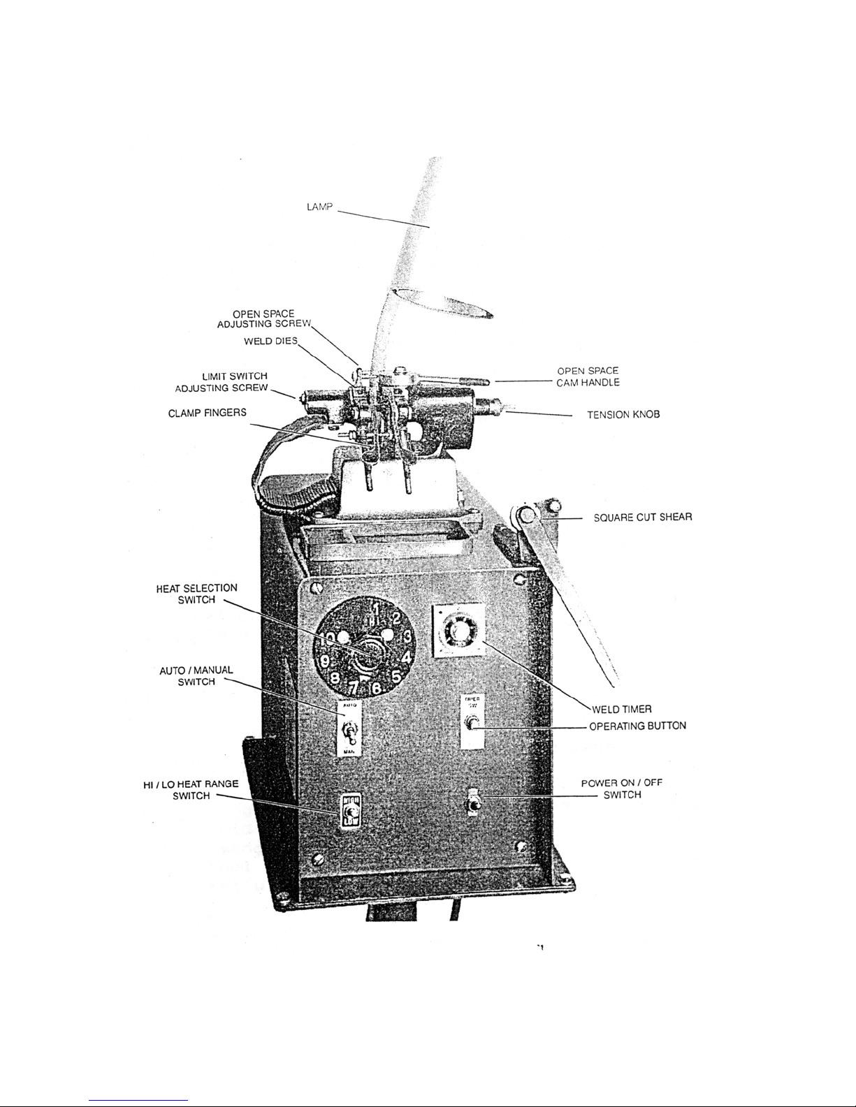
5.2 Set weld heat switch to recommended setting (Ref 8.0)
5.3 Set hi-low range switch (Ref 8.0)
5.4 Set upset pressure (Ref 8.0)
5.5 Rotate space cam to open stop (1/4” between dies)
5.6 Twist conductor end in direction of natural lay.
5.7 Carefully square cut conductor ends so no individual wires
extend beyond cut.
5.8 Select correct size of ceramic sleeve.
5.9 Thread conductor end into ceramic sleeve so as wire ends
are midway through sleeve. Rotating ceramic in direction of
wire lay will assist threading procedure.
5.10 Clamp preset conductor and sleeve into welding die set, so
as ceramic sleeve is centered between open welding dies.
5.11 Thread other prepared conductor into sleeve and allow the
conductor to gently but firmly contact first conductor.
Positive contact to wire ends is important for good weld.
Clamp that conductor into welding dies.
5.12 Rotate and center ceramic sleeve to assure free movement of
conductors during weld process.
5.13 Rotate spacing lever to 0.
5.14 Depress the operation switch, hold for 1 to 3 seconds to
assure a complete weld cycle.
5.15 Unclamp welded conductor and remove ceramic sleeve.
Fracture expendable type sleeve.
5.16 The inside diameter of ceramic sleeve slightly exceeds the
nominal conductor size, therefore the weld zone is slightly
larger than conductor diameter.
5.17 An additional sizing operation, swaging, may be required
should weld zone exceed tolerances on subsequent processing
operations. Micro Products has a special swage tool with
exchangeable tooling available to assist with this sizing
operation.
5.18 The above operation applies to either auto or manual. When
the auto manual switch is in auto, the weld time will be
limited to that selected on the timer.
6

6.0 SPECIAL ADJUSTMENT
6.1 HEADPIECE CLOSED SPACE ADJUSTMENT
Closed space between dies should be 7/32” when the space-
adjusting cam is set at zero.
To make this adjustment first move the space-adjusting cam
to zero, then check the spacing between the dies.
If the space between the dies is not 7/32” at this time,
loosen the locknut on the space adjusting screw. Turn screw
clockwise for more space and counterclockwise for less
space. Once space has been set tighten the locknut on the
space adjusting screw.
6.2 OPEN SPACE ADJUSTMENT
This adjustment determines the amount of upset burr. The
adjustment is made by the space-adjusting cam. A pointer
reflects the cam positioning. Refer to accompanying charts
for approximate settings.
6.3 WELD LIMIT SWITCH
Do not put any wire in the dies when making this
adjustment. Set the space-adjusting cam at #1 on cam. With
a voltmeter measure across the clamp fingers with power
applied to the welder. Press the weld button. The voltmeter
reading should be approximately one VAC with welder at the
highest heat setting. If no voltage is read move the space
cam to higher number. Return the cam to #1 while watching
the voltmeter. The voltage should shut off at #1 on the
cam.
Loosen locknut on the limit switch adjusting screw and
adjust until the welder shuts off at #1 on the space-
adjusting cam. After setting tighten locknut on the limit
switch adjusting screw.
6.4 UPSET PRESSURE
Upset pressure adjustments are obtained by rotating knurled
knob on right hand side of stationary headpiece. When
outside edge of upset adjusting screw is flush with outside
edge of thumb knob, movable headpiece should just close
when pulled to the left by hand. A calibrating screw and
nut located on right hand headpiece will assist in setting
the neutral position. Accompanying charts will assist in
correct setting for neutral position. Accompanying charts
will assist in correct setting for various sizes of wire.
7

7.0 PREVENTIVE MAINTENANCE
7.1 AS REQUIRED:
Flashings must be removed from between welding dies and
clamp fingers with a brush. If flashings are attached so
that they cannot be removed by brushing with a soft wire
brush, they may be broken loose with a scraper made of
fiber or wood.
7.2 DAILY:
7.2.1 Check condition of welding dies and clamp fingers. Replace
Dies or clamp fingers when they have become so worn that
stock does not align or there is slipping of stock in the
dies during upset pressure.
7.2.2 Check condition of clamp springs. Replace all broken
springs or springs that have taken a set.
7.2.3 Check movable head for excessive wear. Have new slide
shafts installed and die seats machined if stock does not
line up when placed in die grooves.
7.3 MONTHLY:
7.3.1 Remove welding dies and clean bottom of die surface with
#120 emery cloth. Do this by placing the emery cloth on a
flat surface plate and rubbing the dies on it, keeping the
surface of the die flat. Wipe die and die seat with a
clean cloth and replace, taking care not to touch either
contact surface with the hand.
7.3.2 Check anneal dies and replace worn or broken parts.
7.3.3 Check insulating fiber pin on limit switch adjusting screw
for broken or frayed ends.
7.3.4 Check upset tension spring and clamp springs. Replace if
springs have been over-stretched and will not return to
normal position.
7.4 QUARTERLY:
7.4.1 Disconnect power to welder. Check contacts on operating
and limit switch. Replace those that are burned.
7.4.2 Check anneal dies and replace worn or broken parts.
7.4.3 Check insulating fiber pin on limit switch adjusting screw
for broken or frayed ends.
7.4.4 Check upset tension spring and clamp springs. Replace if
springs have been over-stretched and will not return to
normal position.
8

7.5 ANNUALLY:
7.5.1 Remove the movable headpiece and check condition of slide
shafts. Wash slide shafts with low residue cleaner,
lightly oil and replace headpiece.
7.5.2 Check condition of headpiece castings. If worn or broken,
replace with new headpiece. If welder is used in an area
where there are corrosive fumes, clean off all oxides and
paint where possible.
7.6 WELDING DIE INFORMATION
Description:
Welding dies – Lower conducting electrode and clamp jaw.
Welding clamp fingers – Upper clamping member.
WELDING DIES IN POOR CONDITION ARE THE MAIN CAUSES OF BAD
WELDS.
7.6.0 CARE OF DIE SETS
7.6.1 Use a Brass or fiber blade to remove particles of flashings
that build-up on die sets. Excessive flash build-up causes
die burns on material and shorting of die sets.
7.6.2 Do not attempt to clamp material that is not suited for
welder into die sets. Undersize materials will slip and
burn die grooves, oversized materials will overstress
clamping parts.
7.6.3 Do not use welding die sets for a vise. These parts will
not withstand the mechanical abuse.
7.6.4 Whenever welding dies are replaces, clean bottoms of dies
and corresponding die seats to a bright and clean condition
before bolting them tightly into place. An oxidized surface will insulate
the welding dies and reduce effective welding voltage.
7.6.5 Welding die sets will wear with use and must be changed
occasionally for good welding results. Keep and adequate
supply of replacement parts available. Wire and rod
slippage is a problem caused by poor die sets and a major
cause of wire breaks.
9

8.0 SUGGESTED SETTINGS
STOCK
STRANDED
SIZE
WIRE
HEAT
TENSION
HEADPIECE
OPEN
SPACE
LIMIT
SWITCH
COPPER 26 GA. 10H 1 5
COPPER 24 GA. 9H 1.5 6
COPPER 22 GA. 8H 2 6
COPPER 20 GA. 7H 3 6
COPPER 18 GA. 6H 3.5 7
NOTE: These settings are approximate and may be varied to suit
needs.
8.1 WELDED STRAND OR BUNCHED COPPER AND ALUMINUM WIRE
CONDUCTORS
THEORY: Welds are formed within a ceramic tube of block and
no filler materials are needed.
Wire ends are resistance heated to a plastic condition and
hot forged together within a ceramic tool, which acts as a
crucible. The resultant coalescence (weld) locks all single
filaments into a solid weld zone…Since strand conductors
have configuration voids on the fraying surfaces, the
plastic material normally forced to the outside on a normal
weld, is forced into the voids eliminating the upset burr
common with standard upset welds. (This type of weld is not
suitable for solid wire.)
10

8.2 CERAMIC FUSION TECHNIQUE
11

9.0 DIAGNOSTIC CHART FOR TROUBLE-SHOOTING WELDERS
WELDING ACTION CAUSE REMEDY
Molten metal is blown out
and ends not joined
Weld heat too high
Stock is too small
Low upset pressure
Lower heat settings
Check size rating of welder
Adjust upset
Weld is complete but is dry
and breaks off below surface
of wire
Upset pressure too great
Lower upset pressure
Weld good but poorly aligned Welding dies & clamp fingers
Starting space
Loose shafts
Replace worn dies and clamp
fingers
Decrease starting space
Return heads to factory
Ends of wire buckle and may
not weld
Upset pressure too great
Low weld heat
Decrease starting space
Increase weld heat
Varying weld results Stock slipping
Varying weld voltages
Wire condition variations
Dies
Flashings
Check Clamp finger pressure
Check electric lines
Clean and tighten
transformer connections to
heads
Clean wire where clamped in
dies
Replace dies
Clean build-up of flash
materials
9.1 ELECTRICAL TROUBLE-SHOOTING OF WELDER
(CAUTION! Extreme care should be exercised when making
these tests. Dangerous voltages are present in the welder.
Only persons familiar with electrical safety precautions
should perform these tests.)
9.1.1 TROUBLE-SHOOTING TABLE
(See section 9.1.3)
This electrical trouble-shooting table is furnished as a
suggested method of trouble-shooting the welder. The
individual steps of the table should be performed in the
order given, to make the tests valid. The electrical
schematic (section 10) furnished for these tests show the
table test points. The table may be used for welders with
a different but closely related wiring by using
corresponding test points. (During all tests, line voltage
should be connected to L1 & L2 of the welder. The heat
switch should be set to the #1 position.
9.1.2 FINAL ELECTRICAL CHECKS
Set the heat switch to the number 1 position, connect the
voltmeter across the welding dies. Press the operating
switch. The meter reading will typically be less than 10
VAC. Consult the weld specification sheet for this value.
12

Rotate the heat switch through all settings. If the
voltage is not read at any setting, the heat switch may be
defective. Actuate the weld limit switch; observe the
reading goes to zero. Release the weld limit and operating
switches, the reading should remain at zero.
9.1.3
TEST LEAD
CONNECTION
METER
READING
PROBLEM
IF NO
READING
PRESS
OPERATING
SWITCH
WELD LMIT
SWITCH
ACTUATED
AUTO/MANUAL
SWITCH
L2 FU1-1 115VAC Bad fuse connection MANUAL
L2 FU1-2 115VAC Open fuse
L2 PB1-1
L2 PB1-2
L2 LS1-1
115VAC
115VAC
115VAC
Open wire to operating
switch
Bad operating switch
Open connection to weld
limit switch
X
X
L2 LS1-2 115VAC Open weld limit switch
L2 CR1-1 115VAC Open wire to contactor
L2 CR1-2 115VAC Bad contactor X
L2 S1-1
L2 TR1-8
115VAC
115VAC*
Open wire to heat switch
Bad timer circuit momentary
X
AUTO
Note: to perform repair consult section 13 for parts
identification.
S2 closed for all tests.
*Voltage present for 1 sec. when timer is set to 1 sec.
13

14

11.0 SAFETY REMINDERS
The following accident prevention information is presented
to eliminate potential hazards while operating, inspecting
or repairing Micro-Weld Electric resistance welding
equipment.
Important safety compliance information for Micro-Weld
Welders.
GENERAL
1. Qualified personnel, prior to using equipment, must
instruct an operator on basic operation and
malfunction methods.
2. Safety eyeglasses must be worn by all personnel
operating or servicing welders.
3. Use safety equipment properly and keep safety
equipment on welders.
4. Determine that both operating voltages and hertz
(cycles) of power supply correspond to ratings listed
on welder nameplate located on welder housing.
5. Check nameplate ratings and keep within capacities and
material categories stated therein.
6. Adjustments or repairs must be made by persons
thoroughly familiar with operating principles of
welder.
7. Welder must be disconnected from power supply prior to
maintenance or repair procedures.
ELECTRICAL
1. Refer to national Electrical Code and local
regulations for adequate electrical wiring to power
welder. Do not operate welder with inadequate
electrical power supply cords or cable.
2. All welders must be grounded through power supply and
welder ground connection terminal securely tightened.
3. All welders must be able to be disconnected from power
source either by a double breaking disconnect switch
or unplugged by standard rated plugs.
4. All welders must be fused to prevent injury should an
electrical malfunction occur. Welders must never be
fused for an ampere load that exceeds the ratings
stated on welder nameplate. Normally welders are fused
using the nameplate rated load; time lag parameters
functional to standard fuse allow this specification.
5. Electric power cords to welder must be kept in good
condition. Report any damage or potential hazards to
maintenance personnel.
6. The weld head selection switch, potentiometer or range
selection devices must not be changed to a new
position while a weld operation is in process.
15

12.0 BUYERS GUIDE
HOW TO ORDER PARTS:
You must provide
1. Machine Model
2. Machine Serial Number
3. Voltage
Then identify part(s) on part list in section 13 and
provide MICRO with the circled number
CALL MICRO at A.C. 630-787-9350
Or Toll free at 800-872-1068
Provide MICRO with your company name and purchase order
number.
16

13.0 PARTS LIST
17

18

19

PARTS LIST GPO
MODEL/
PART NO.
DESCRIPTION
ITEM #
GPO-01A Head assembly 32118
GPO-03 Tray assembly 42051
GPO-04 Transformer cap 52001
GPO-05A Basic head assembly 32133
GPO-05B Interior mounting plate 32132
GPO-05C Cherry micro switch 57851
GPO-06A Basic head assembly 32133
GPO-06B Bearing spacer 32057
GPO-06C Bearing 48400
GPO-06D Limit switch adjusting screw 52008
GPO-06E Shaft cover 32056
GPO-07A Open head stop screw 32028
GPO-14 Housing assembly 42075
GPO-14C Basic head brass pin 93144
GPO-14E Basic head groove pin 92608
GPO-14FP Front door 42050
GPO-14BP Back door 42033
GPO-18 Shunt insulator 37728
GPO-21 Tension adjusting knob 35564
GPO-22 Tension adjusting worm 32087
GPO-23 Tension screw nylon 35516
GPO-24 Tension spring 32059
GPO-25A Space cam assembly 32003
GPO-26 Repeating cam stop 32000
GPO-27 Cam bushing 32002
GPO-28 Space cam attaching bolt 90203
GPO-29 Closed space adjusting screw 32082
GPO-34 Insulating sleeve 37709
GPO-38 End cover plate 32054
GPO-39 End cover attaching screw 91055
GPO-51A Omron timer 57693
GPO-51B Omron socket 57695
GPO-51C Omron adapter 57694
GPO-51D Omron cover 57696
GPO-53 Fuse holder 58091
GPO-54 Fuse 58083
GPO-62 Tap switch plate 55510
GPO-63 Tap switch 57800
GPO-64 Heat switch plate 55510
GPO-68 GPO radius groove dies (20 & 18 ga) 32123
GPO-69 GPO radius groove dies (22-24-26 ga) 32124
GPO-70 Clamp finger left wide 32016
GPO-71 Clamp finger right wide 32017
GPO-74 Finger stop pin 32020
GPO-75 Clamp finger return spring 80007
GPO-76 Basic head spring screw 91026
20
Table of contents
Popular Welding System manuals by other brands

Miller
Miller Spectrum 625 X-TREME owner's manual

Lincoln Electric
Lincoln Electric INVERTEC V350-PRO CE Operator's manual

Lincoln Electric
Lincoln Electric Weldanpower 125 Operator's manual

SWS
SWS ALUMTIG 200 quick start guide

Plasson
Plasson PFS Monomatic instruction manual

Telwin
Telwin TECNICA 141-161 Repair manual

Miller Electric
Miller Electric 350 VS owner's manual

Plasma
Plasma PTW 500 manual

NewArc
NewArc Viper 2500s Operational manual

NewArc
NewArc R7000 Operational manual

Campbell Hausfeld
Campbell Hausfeld WS0970 Operating instructions and parts manual

Lincoln Electric
Lincoln Electric SPEEDTEC 200C BR Operator's manual