Kuzma Air Line User manual

THEORY BEHIND»AIR LINE« TANGENTIAL AIR BEARING TONEARM
KUZMA AIR LINE AIR BEARING TONEARM
1. Basic Theory
2. Principles of air bearing
3. Practical solutions to problems of air bearings
4. Description of the »Air Line air bearing tonearm

1. BASIC THEORY
In principle we all agree that a cartridge should follow the same line when
playing an LP as the cutter head was travelling when cutting grooves on the
master disc. This is tangential on any groove in a straight line from the outer
edge of an LP towards the centre of the record. Bearing this in mind it should
not be forgotten that a cartridge can read very small levels of information from
the groove of even a few molecules in size. This means the body of the
cartridge must be still if we are to retrieve this information accurately.
Let us first look at the most common factor involved in tonearm and cartridge
assembly; its capacity to follow the grooves as they have been cut. Accuracy in
this is not in practice easily achieved. The most common solution is the use of
a pivoted arm with an offset angle for the cartridge. With this compromise we
can obtain a remarkable approximation towards a theoretically ideal geometry
of zero degree error in any groove. A pivoted arm when optimally adjusted
can have a tangential error below 2 degrees with distortion levels below 1%
which of course varies across the record. If a tangential tonearm is perfectly
constructed and adjusted this figure would be zero.
Many factors apart from optimum tracking geometry affect faithful
reproduction of the grooves and are inolved in tonearm design Both pivoted
and tangential arms should have structural rigidity with minimum vibration of
headshell tube bearing and all other parts. As the tonearm must move
bearings should show minimum friction and have minimal allowance for
movement in those directions which will affect accurate tracking of the grooves.
In addition tonearms should be constructed in such a way that they are easy to
adjust and hardwearing enough to be used for many years.
In most cases these goals are easily achieved with pivoted tonearms but only up
to a point. Structurally rigid and low noise bearings can be produced but the
geometry and behaviour of the tonearms under dynamic conditions are not
optimal. With tangential tonearms we achieve optimal geometry with a
different approach in the use of various bearings but structural rigidity under
static and dynamic conditions is compromised. Both types of tonearm can be
adjusted to near perfection by making changes in VTA and azimuth.

In both types of tonearm the choice of headshell tube shape and material have
similar effects. The main structure can also be optimally designed in both
cases. So what really are the main differences which affect reproduction can
they be heard and what makes some of the best tangential tonearms sound so
different and so much better than the best pivoted arms?
Certainly if only perfect tracking geometry mattered things would be very
simple. In practice even some tangential tonearms compromise on optimal
geometry.
Some tangential tonearms use electronic controls with servo mechanisms to
move a classic pivoted tonearm along a straight line. This compromises
structural rigidity and introduces vibration and noise into the system. Due to
the servo system there is a continuous mistake in tracking when it notices a
difference from optimal geometry and corrects the position of the tonearm.
Another type of tangential tonearm uses very low friction bearings. The whole
tonearm assembly is moved along via forces on the needle and cantilever with
opposite forces of mass resistance and bearing friction. Such bearings have
higher friction and noise than in the best pivoted tonearms. To achieve the
lowest possible noise small bearings are used which take a low load and are not
stiff. To achieve minimum friction there must be some play in the bearings
which then resonate and allow non-tangential movements along the tube.
An airbearing is a natural choice as it allows movements in both vertical and
horizontal planes with practically no friction. In practice we must solve a
number of problems. There are different types of air bearings which have
different properties. Most of them have zero friction but they do allow
movement of the bearing and cartridge in directions which should not move at
all.

2. PRINCIPLES OF AIR BEARINGS
Let us first look at the main principle of the simplest air bearing. This is a flat
bearing for moving loads on a flat surface. (Fig A )
Fig. A: Flat bearing
Imagine a flat surface. On top of this surface we have a block of metal. If we
provide air flow between the flat surface and the bottom of the block then the
block will rise above the flat surface. With very little force we can push it along
as if it were on a smooth ice surface. In our case the thin film of air which is
between the surfaces has practically zero friction so that the force required for
movement to occur is really very small. To provide this airflow we need to
bring air between the two surfaces. We can make a hole in the block and
provide air there. Due to atmospheric pressure all around us we must provide
pressurised air above that of the atmosphere in order for air to flow from the
hole. If this pressure is high enough it will lift the block above the flat surface
and there will be a small gap between the flat surface and the block. This gap
will be proportional to the mass of the block air pressure and the size of the
surface of the block and air will start flowing through the gap to the outside.
The same effect can be gained if we provide holes in the flat surface. Where the
holes are covered with a block there will be a lifting effect.

Imagine what will happen if you press the floating block down in the middle.
The gap will be reduced and restored after release of pressure. Thus the block
will move up and down. This system is unstable and sensitive to outside forces.
Movement is possible in all directions along the flat surface. If we apply force
to one corner of the block that side of the block will be easily pushed down the
gap will close and friction might increase to such an extent that we are unable to
push the block along the surface. Such a bearing is very unstable and in
practice of very limited use. To make practical use of such a bearing we must
limit movements in certain directions while allowing frictionless movement in
those desired.
The obvious choice is to replace a flat surface with a round one: a rod around
which our block is captured like a sleeve (Fig. B C).
Fig.B: Round Bearing-cross section
Fig. C: Round bearing-side view

If we bring pressurised air between the sleeve and the rod the compressed air
will « lift the block«. Because the sleeve is surrounding the rod however
forces are equal on all sides and we have a sleeve floating around the rod
without touching any surface. We can move the sleeve along the rod and this
movement can be used as horizontal movement of the tonearm. At the same
time we can rotate the sleeve and we can use this movement as vertical
movement of the tonearm. This is in theory. What happens if we apply outside
forces. The sleeve and parts like tube headshell counterweight and cartridge
all have a mass. There are forces moving the tonearm along and up and down
and forces pulling the cartridge along the tube in the direction of disc rotation.
If we remember what happened with the flat block when we pushed it down we
have the same problem. Fixing the sleeve and moving the rod makes no
difference regarding this unstable situation. We need to stabilise the situation
so that the sleeve will not be moved in any direction other than along the rod
axis (horizontal movement) and in rotation (vertical movement).
The main problem is that the cushion of air in the gap behaves like a spring.
This means that under dynamic conditions the cartridge and tube assembly will
move in various directions and the cartridge will not stay in the position of the
cutter head but will be pulled along the groove and twisted due to the forces

moving the cartridge in the grooves. Of course this also happens in pivoted
arms but due to differences in construction ie. loose bearings vibration of
bearings and other parts.
To practically avoid this effect we must use a stiff bearing which automatically
reacts to these external forces. Construction of a stiff airbearing is dependent
on the air gap air pressure and bearing surface. Higher air pressure means a
stiffer bearing which can carry a heavier load. The same effect can be achieved
by a small air gap between the moving parts of the bearing. In the best bearings
the gap is limited to a construction of 10 microns. This is actually less than in
most pivoted tonearms which have air slack in their bearings to move!!
A stiff bearing will not in itself stop the tonearm bearing from moving closer to
one side of the bearing shaft when force is applied to one side. The bearing
must be constructed in such a way that it is self-centering. That means in
practice if force is applied to one end the gap will decrease but a properly
constructed bearing will respond to this by increasing airflow to the smaller
gap restoring the equilibrium.
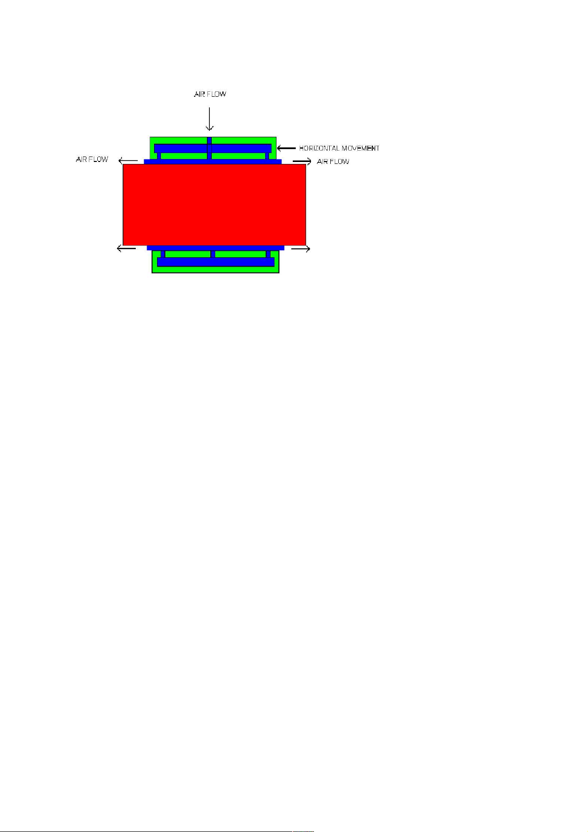
In practice the gap stays the same if forces are not overloading the bearing and
the cartridge position under dynamic conditions remains stable. If we apply
force to one end of the bearing sleeve we have the same problem. To have a
self-centering effect along the axis as well as along the diameter of the rod the
airbearing must be properly designed.
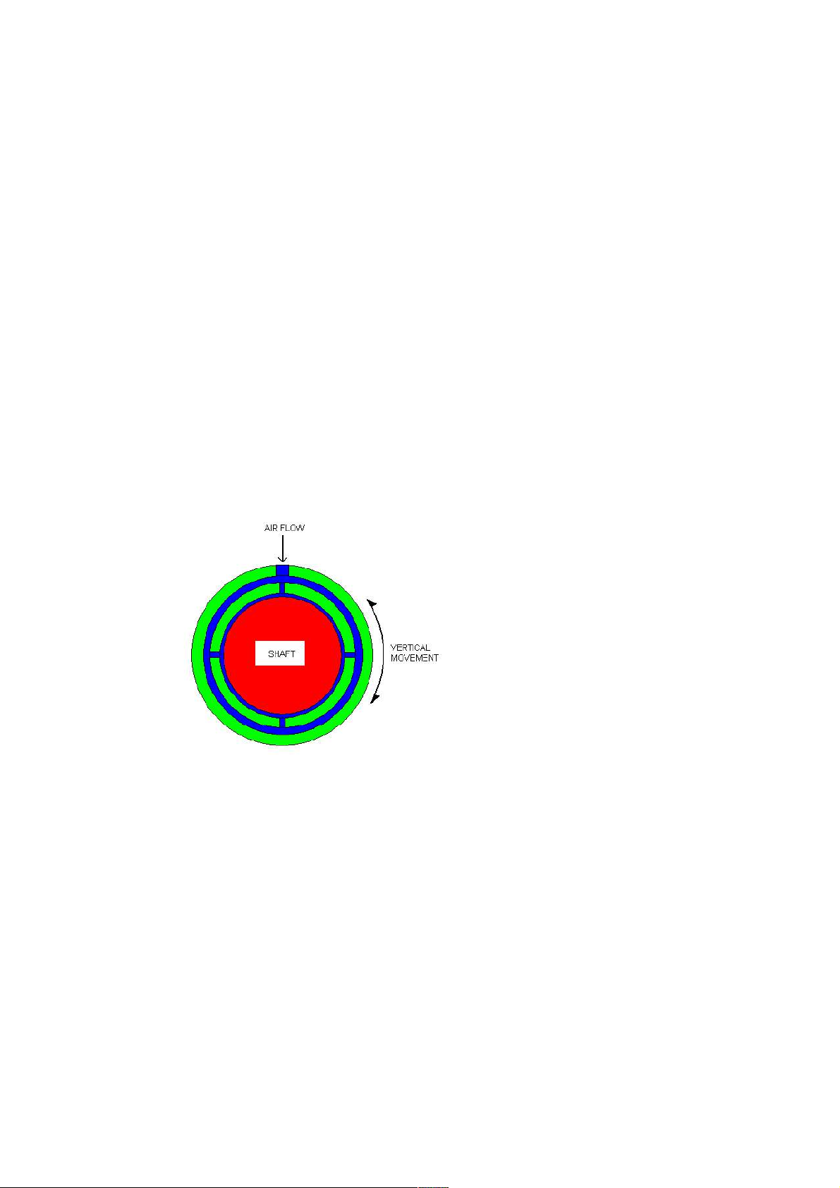
An airbearing has few holes through which air is forced but most such bearings
behave poorly under dynamic conditions. If the bearing were to have only a
few holes then the bearing would twist moving the cartridge away from a
tangential line.
The best solution is an almost infinitessimal number of holes which can be
obtained by use of porous material with holes of 10-20 microns in size. This
makes the most stable bearing and in our case forces equivalent to a few kilos
applied to the tonearm will maintain the gap as a stiff bearing with practically
zero friction.
Another positive aspect of the tangential tonearm is its lack of bias forces.
Close inspection shows that the forces pulling the cartridge along the groove are
dependent on the modulation of the groove the flatness of the record and the
eccentricity of the grooves. In a tangential tonearm all these forces are pulling
straight forward along the tube and the cartridge can not move along the axis of

the tube when a proper airbearing is used in the construction of the tonearm. In
pivoted tonearms due to construction of an offset angle of the headshell forces
are pulling the cartridge along the tube and pushing the cartridge towards the
inner groove. To compensate for this we use antiskating forces or bias. As
these forces change all the time due to rotation and the modulation of music
they vary in size and direction and cause the cartridge to behave in a very
unstable manner. The needle travels along the tangent in the groove back and
forth and directly affects the signal by modulating it with the vibration of the
cartridge and headshell combo. This increases wow and flutter and makes the
whole sound unstable and unfocused. In a tangential tonearm this force tries to
pull along the tube but these and other movements are negated by a properly
designed airbearing itself. Thus the cartridge is kept in a position as close as
possible to that of the cutter head.
3. PRACTICAL SOLUTIONS TO PROBLEMS OF AIR BEARINGS
For an airbearing tonearm to function properly certain criteria must be fulfilled.
One is to have an airbearing constructed in such a way that it behaves as a stiff
bearing in all unwanted directions and have zero friction in desired ones. An
airbearing with a high load capacity and with self-centering properties is

mandatory. This means among other things that there must be only a small
gap between the shaft and the bearing and as many small holes as possible as air
outlets. Since we are talking about a few thousandths of a mm we must supply
clean air at high pressure.
Air supply:
Clean air means air that is free of moisture small particles of dust and other
contaminants such as oil which may come from air compressors.
Air pressure:
There are different types of compressors. Their basic function is to compress
air to the level necessary for optimal airbearing funtion which is about 3-4 bars
or 50-80 psi. Air compressors are unfortunately very noisy machines. In small
compressors an electric motor is usually used to rotate a piston which in return
compresses the air. This air flows out of the compressor in pulses. To achieve
steady airflow we need to store air in a reservoir. On the outlet of the reservoir
is a pressure valve which regulates output pressure. The reservoir smooths
pressure pulses like a capacitor in electricity and the pressure valve smooths it
further to a working pressure of about 4 bars.
Air contains moisture. The level of water contained in air is called the relative
humidity. At higher temperatures the same volume of air can hold a higher
amount of water. Relative humidity therefore depends on air temperature. For
example one litre of air contains a certain amount of water. When we compress
air to 8 bars (1 bar is normal air pressure) we must compress 8 litres of air into
the volume normally occupied by one litre. Unfortunately we now have 8
times more water vapour. As during compression the air temperature is raised
the air can hold more water but as the air cools down in the reservoir and along
the pipes it can no longer hold such an amount of water and condensation
occurs blocking airflow in pipes and bearing. This moisture must be removed
from the system and this done using air dryers. There are different types of
drying processes and different dryers.
The quietest compressors on the market are oil lubricated. Their noise level is
like those used in fridges and could be used in a living area. Unfortunately due
to oil lubrication small amounts of oil mist leaks into the air flow and has to be
removed with oil filters.
We have chosen an air compression system with filters and dryers which
consists of a compressor which automatically fills the reservoir drains out

moisture and filters for dust particles and oil mist. Air is dried through a
filtering system. The working pressure is fine adjusted and held constant with a
pressure regulator.
The compressor is best situated in a separate room permanently plugged into
the mains and left switched on. A 4 mm PVC hose which can be anything up to
40 m long runs to the tonearm. On the tonearm is a valve which regulates
airflow. When the valve is open the air is consumed from the reservoir and the
tonearm moves without friction. When the pressure in the reservoir drops
beyond a certain point the compressor automatically switches on to refill the
reservoir and then automatically switches off. So when the valve on the
tonearm is closed the bearing does not function there is no consumption of air
and the compressor stays switched off. Due to the automatic drainage system
on the compressor occasional leakage of air is heard when liquid drains from
the reservoir into the drainage bottle.
Maintenance of the compressor consists of an occasional oil level check and
emptying of the drainage bottle about every 6 months. In the summer or in
areas with higher humidity the bottle may need emptying more often.
4. DESCRIPTION OF THE » AIR LINE « AIR BEARING TONEARM
The tonearm base has a VTA adjustment which holds the stainless steel shaft of
the main bearing. In the main carrier are fixed the airbearing tonearm tube and
counterweight holder. The airbearing is capable of carrying a load of 3 – 4 kg.
with a 4 bar working pressure.

The main tube is machined from three solid blocks of aluminium and made into
a stiff hollow conical tube. Azimuth adjustment is controlled by a zero play
non-resonant locking mechanism which allows for fine repeatable adjustments.
The solid aluminium headshell is shaped to minimise resonance and further
damped by the use of four ribs. The tube is internally damped. The shape of
the counterweight minimises its own resonance as well as resonance of the
carrier beam.
One carrier tube leads wires in a loop to the sliding bearing while the second
has a flexible tube which supplies air into the bearing. At one end of the
tonearm is the valve for regulating the air flow while there is a small air
pressure guage at the other.
The cueing mechanism can be adjusted according to the height of the tonearm.
The VTA mechanism is locked with a lever and allows fine adjustments over a
10 mm range to a precision of 0.05 mm. The basic height of the tonearm is
adjusted by a specially designed collar which can also hold the whole assembly
at a certain height while adjustment of tonearm geometry is made. While
changing height or VTA there is practically no change in azimuth due to
precision in construction.
The tonearm has a mass of 2 kg and fits into the same mounting hole as Stogi
tonearms. The wiring is from high quality copper or silver wires unbroken in
one length from headshell to RCA or XLR connectors.
Air is supplied via a 4 mm plastic tube which can be fitted anywhere.
Connection is via a Quick fit 4 mm connectors which are standard in
compressed air supply. The air hose should not run outside in temperatures
below freezing point. Tube length can be simply adjusted by cutting with a
knife. An adequate number of connectors are supplied to enable various
connections to be made as well as ample 4 mm tubing. The main drying filter
with its stand is best located near to the tonearm.
Maintenance of the air bearing consists of occasional cleaning of the bearing
shaft with a clean cloth (supplied) and alcohol.
The tonearm is supplied as a package consisting of tonearm and complete air
supply with very quiet compressor reservoir all filters dryers and tubes etc.

The system of air supply seems to be complicated at first but is actually simple
to use and certainly worth the effort in view of the improvement in sound
quality obtained.
Franc Kuzma
Other manuals for Air Line
1
Table of contents
Other Kuzma Turntable manuals

Kuzma
Kuzma Stabi S User manual

Kuzma
Kuzma 313VTA User manual

Kuzma
Kuzma STABI R User manual

Kuzma
Kuzma Air Line User manual

Kuzma
Kuzma STABI M User manual

Kuzma
Kuzma XL AIR KIT User manual

Kuzma
Kuzma 4Point User manual

Kuzma
Kuzma Stabi S PS User manual

Kuzma
Kuzma Stabi S User manual

Kuzma
Kuzma Stabi XL4 User manual

Kuzma
Kuzma Stabi XL User manual

Kuzma
Kuzma Stogi S User manual

Kuzma
Kuzma 4Point User manual

Kuzma
Kuzma Stabi S12 User manual

Kuzma
Kuzma Stabi XL2 User manual

Kuzma
Kuzma STABI S PS AC User manual

Kuzma
Kuzma Stogi S User manual

Kuzma
Kuzma 4POINT 9 User manual

Kuzma
Kuzma STABI REF PS 2 User manual

Kuzma
Kuzma Kuzma Stabi Reference Turntable User manual