manuals.online logo
Brands
  1. Home
  2. •
  3. Brands
  4. •
  5. COMECO
  6. •
  7. Transmitter
  8. •
  9. COMECO TRA1 User manual

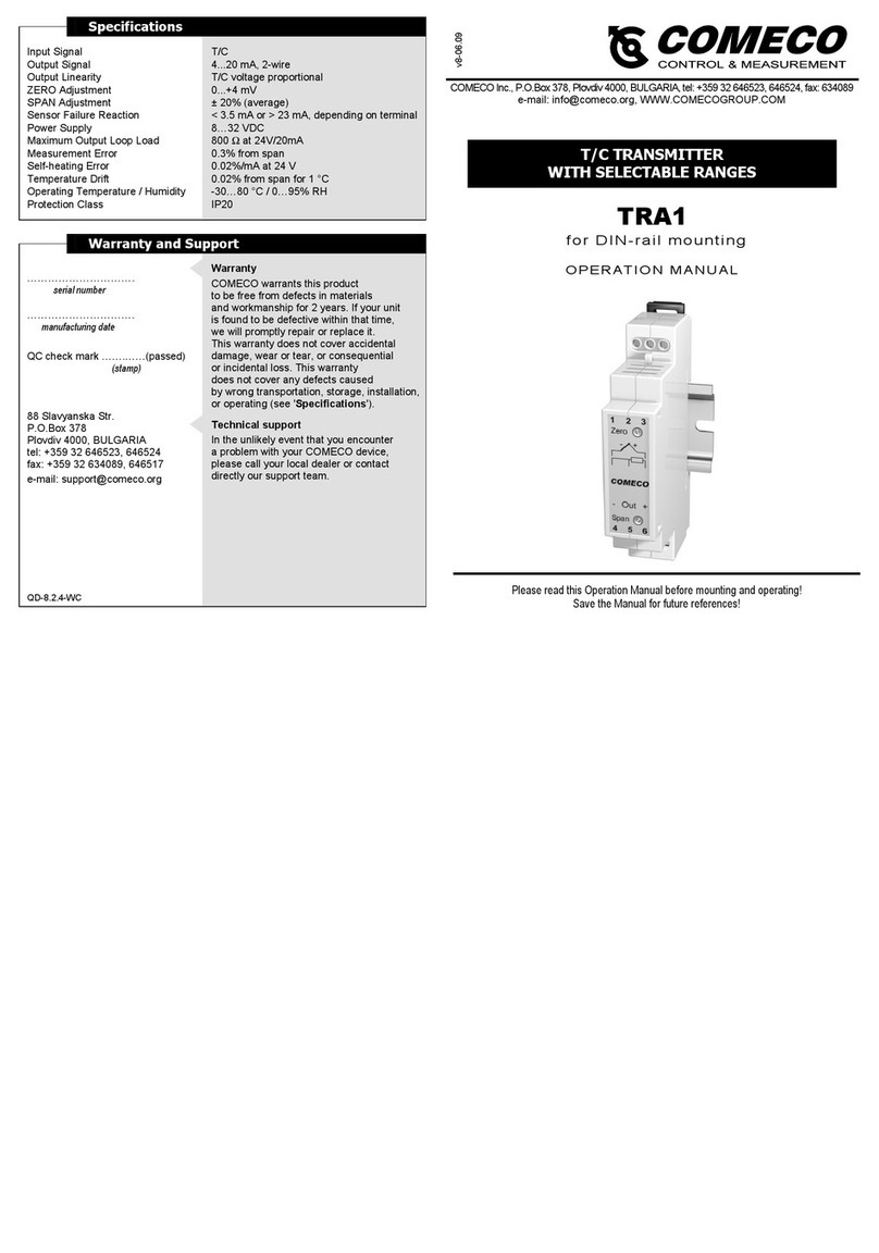
COMECO TRA1 User manual

Specifications
Input Signal
Output Signal
Output Linearity
ZERO Adjustment
SPAN Adjustment
Sensor Failure Reaction
Power Supply
Maximum Output Loop Load
Measurement Error
Self-heating Error
Temperature Drift
Operating Temperature / Humidity
Protection Class
T/C
4...20 mA, 2-wire
T/C voltage proportional
±50 °C ±10%
±10%
> 23 mA
8…32 VDC
800 Ωat 24V/20mA
0.3% from span
0.02%/mA at 24 V
0.02% from span for 1 °C
-30…80 °C / 0…95% RH, non-condensing
IP20
Warranty and Support
………………………….
serial number
………………………….
manufacturing date
QC check mark …….……(passed)
(stamp)
88 Slavyanska Str.
P.O.Box 378
Plovdiv 4000, BULGARIA
tel: +359 32 646523, 646524
fax: +359 32 634089, 646517
e-mail: support@comeco.org
QD-8.2.4-WC
Warranty
COMECO warrants this product
to be free from defects in materials
and workmanship for 2 years. If your unit
is found to be defective within that time,
we will promptly repair or replace it.
This warranty does not cover accidental
damage, wear or tear, or consequential
or incidental loss. This warranty
does not cover any defects caused
by wrong transportation, storage, installation,
or operating (see 'Specifications').
Technical support
In the unlikely event that you encounter
a problem with your COMECO device,
please call your local dealer or contact
directly our support team.
COMECO Inc., P.O.Box 378, Plovdiv 4000, BULGARIA, tel: +359 32 646523, 646524, fax: 634089
e-mail: [email protected]g, WWW.COMECOGROUP.COM
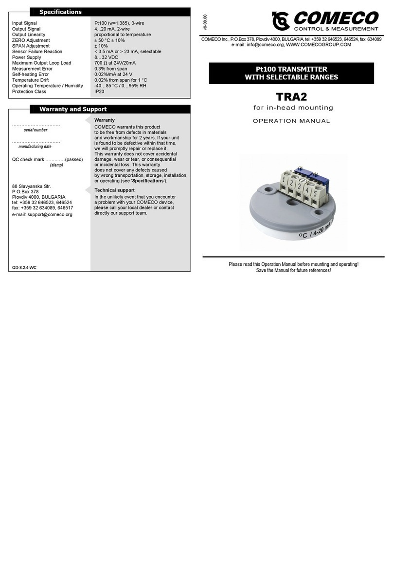
TRA1
for in-head mounting
OPERATION MANUAL
Please read this Operation Manual before mounting and operating!
Save the Manual for future references!
T/C TRANSMITTER
WITH SELECTABLE RANGES
v9-11.11
Overview
The T/C transmitter TRA accepts input
signals from various thermocouple types.
It allows on-site selection of both
the T/C type and the input range and
converts the input into standard 2-wire
4…20 mA signal, proportional
to the thermocouple output voltage,
that can be safely sent over long distances
to remote indicators, data loggers,
or controllers.
Mounting and Wiring
Important note:
Always use
the protective cover
to prevent the electronics
from getting dirt
on the soldering pads
as well as getting
electrostatic discharge
by accidental touch.
Mounting
♦TRA for in-head mounting is designed
to be incorporated inside protective heads
with 33 mm distance between centers
of the female threaded openings.
♦Install the transmitter into the temperature
probe head using two M4 screws with
appropriate length. To ensure vibration
proof, use special screws with springs.
♦Your TRA can also be easily mounted
on every 35 mm rail conforming
to EN50022 by the means of a special
snap-on accessory, offered separately.
Wiring
♦Connect the T/C sensor wires
to the transmitter input
via terminals 1(+) and 2(-),
as illustrated on the wiring diagram.
♦Wire the output current loop
through terminals 4(+) and 5(-).
♦In order to minimize measuring errors,
make sure the connecting screws
are tightened enough.
Configuring and Calibrating
Configuration
To be carried out
before calibration!
♦Open the plastic cap to expose
the five soldering jumpers,
each of which consisting
of 3 solder pads.
♦Set the desired T/C type
and input range by soldering
the respective jumper pads
according to the charts.
♦Put the plastic cover on.
Calibration
It is suggested that
the calibration be checked
at least once a year.
♦Connect the transmitter
(see 'Wiring').
♦Apply an input signal to give
an output of approximately 12 mA
and leave the unit for 15 min,
if possible at the ambient
temperature it is intended
to work at.
♦Apply INmin corresponding
to the desired minimum
input signal.
♦Adjust 'Z' potentiometer
to get Iout = 4.00 mA.
♦Apply INmax corresponding
to the desired maximum
input signal.
♦Adjust 'S' potentiometer
to get Iout = 20.00 mA.
♦Repeat the last 4 steps
until readings converge.
♦Secure the potentiometers
with lacquer.

Other COMECO Transmitter manuals

COMECO TRA1 User manual

COMECO

COMECO TRA1 User manual

COMECO PHG User manual

COMECO

COMECO PHG User manual

COMECO TRA1 User manual

COMECO

COMECO TRA1 User manual

COMECO TRA2 User manual

COMECO

COMECO TRA2 User manual

COMECO TRA1 User manual

COMECO

COMECO TRA1 User manual

Popular Transmitter manuals by other brands

Audiovox Prestige APS-2K4MS Programming guide

Audiovox

Audiovox Prestige APS-2K4MS Programming guide

WIKA MH-1 operating instructions

WIKA

WIKA MH-1 operating instructions

Wireless Devices WD2 Operation manual

Wireless Devices

Wireless Devices WD2 Operation manual

SEA EAGLE quick start guide

SEA

SEA EAGLE quick start guide

Radio Shack Six-Element Triple-Drive FM Antenna owner's manual

Radio Shack

Radio Shack Six-Element Triple-Drive FM Antenna owner's manual

Comet T3110Ex How to use

Comet

Comet T3110Ex How to use

Electia CS185 user guide

Electia

Electia CS185 user guide

ABB STT04 instruction manual

ABB

ABB STT04 instruction manual

ASCOM HMT1000 - DATASHEET 1 datasheet

ASCOM

ASCOM HMT1000 - DATASHEET 1 datasheet

Endress+Hauser HART iTEMP TMT182B operating instructions

Endress+Hauser

Endress+Hauser HART iTEMP TMT182B operating instructions

Kramer TOOLS TP-104 user manual

Kramer

Kramer TOOLS TP-104 user manual

Talitor BW1101 user guide

Talitor

Talitor BW1101 user guide

LRS T9601 Setup guide

LRS

LRS T9601 Setup guide

Comnet FVT80D4SFP Installation and operation manual

Comnet

Comnet FVT80D4SFP Installation and operation manual

AODELAN E4 user manual

AODELAN

AODELAN E4 user manual

blukii Smart Key Go Mini manual

blukii

blukii Smart Key Go Mini manual

FlowLine EchoBeam LR83 Series quick start guide

FlowLine

FlowLine EchoBeam LR83 Series quick start guide

Amazilla iWing SR-HD user manual

Amazilla

Amazilla iWing SR-HD user manual

manuals.online logo
manuals.online logoBrands
  • About & Mission
  • Contact us
  • Privacy Policy
  • Terms and Conditions

Copyright 2025 Manuals.Online. All Rights Reserved.