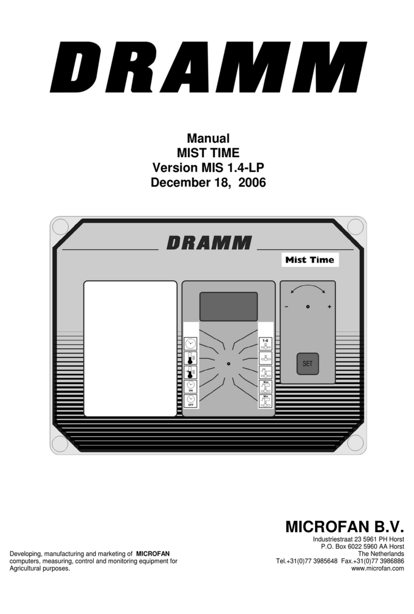
Microfan BRAVO TOUCH K User manual

LinkedIn www.microfan.com
QUICK START GUIDE
BRAVO TOUCH K
1Download the quick start guide in another language ............................... 2
1.1 Bravo Touch K Quick start guide EN ______________________________ 2
1.2 Bravo Touch K Schnellstartanleitung DE ___________________________ 2
1.3 Bravo Touch K Guide de démarrage rapide FR______________________ 2
1.4 Bravo Touch K Snelstartgids NL _________________________________ 2
2Download the full manual ......................................................................... 2
3Safety instructions and general warnings................................................. 3
3.1 General warnings _____________________________________________ 3
3.2 Safety warnings ______________________________________________ 3
3.3 Wiring precautions ____________________________________________ 4
3.4 Disposal ____________________________________________________ 4
4Operating the display ................................................................................ 5
5User menu functions.................................................................................. 6
6Installer menu functions ........................................................................... 6
7Alarm overview.......................................................................................... 7
8Front board overview ................................................................................ 7
9Bottom board overview ............................................................................. 8
9.1 Detail A: jumper settings _______________________________________ 9
9.2 Detail B: connections __________________________________________ 9
10 Technical specifications........................................................................... 10

Q u i c k _ s t a r t _ 2 0 2 0 0 5 1 5 _ B R A V O _ T O U C H _ K _ E N _ V 1 . 0 2 . 0 2 . d o c x P a g e 2 | 12
1Download the quick start guide in another language
The Bravo Touch K Quick start guide is available in various languages. Download the version you need via
the QR-code. You can also find more information via www.microfan.com.
1.1 Bravo Touch K
Quick start guide EN
1.2 Bravo Touch K
Schnellstartanleitung DE
1.3 Bravo Touch K
Guide de démarrage rapide FR
1.4 Bravo Touch K
Snelstartgids NL
2Download the full manual
Scan the QR-code below to download the latest full manual of the BRAVO TOUCH. This manual contains all
necessary information to install and use the BRAVO TOUCH SL, 06, 10 and K. You can also find more
information via www.microfan.com.
Remark: The full manual is currently only available in English.

Q u i c k _ s t a r t _ 2 0 2 0 0 5 1 5 _ B R A V O _ T O U C H _ K _ E N _ V 1 . 0 2 . 0 2 . d o c x P a g e 3 | 12
3Safety instructions and general warnings
Carefully read, understand, and follow all the warnings and instructions provided by Microfan B.V. to safely
use our products. These warnings and instructions are found on the equipment, in manuals, in brochures, on
our website, or by contacting us. The selection and application of Microfan B.V. products remain the
responsibility of the equipment installer or end user. Microfan B.V. accepts no responsibility for the way its
products are incorporated. All Microfan B.V. products must be supplied to the end user with appropriate
warnings and instructions as to safe use and operation. Microfan B.V. assumes no liability for any personal
injury, property damage, losses, or claims arising from misapplication of its products.
3.1 General warnings
WARNING
•Read and understand all the warnings and instructions provided by Microfan B.V. before
installing, operating, or servicing any of our products.
•All work must only be performed by qualified personnel.
•The product must only be set up, used, or stored in places that are not accessible to
children.
•Handle the product with care; impacts, shock or fall even from low heights will damage it.
•Do not expose the product to direct sun irradiation, strong heat or cold.
•After installation, always check all settings to ensure they work correctly.
•Do not use running water to clean your computer. The computer is splash proof, not
waterproof!
•It is of the utmost importance that the installation is equipped with a solid alarm system
that is tested for correct operation at least once a day.
3.2 Safety warnings
WARNING
•Do not wear any metal or conductive materials, such as jewelry (necklaces, bracelets,
rings, etc.) during installation or service on electrical parts or components.
•Always shut off the power before opening the housing.
•Never remove components or wires from electronic boards when the unit is switched on.
•Do not use an improper voltage source.
•Make sure all terminal screws are tightened correctly.
•Always make use of the supplied cable glands when installing cables to the controller.
•After installation, unused cable glands must be sealed to prevent water, dust, and other
substances from entering the controller.
•If you have a reason to believe that the device can no longer be operated safely,
disconnect it immediately and make sure it is not operated unintentionally.

Q u i c k _ s t a r t _ 2 0 2 0 0 5 1 5 _ B R A V O _ T O U C H _ K _ E N _ V 1 . 0 2 . 0 2 . d o c x P a g e 4 | 12
3.3 Wiring precautions
WARNING
•For all weak current connections, always use shielded cable.
•For all high voltage power connections, always use shielded cable.
•For communication connections, always use twisted pair shielded cable.
•Do not connect the shielding of weak current connections to the ground block (PE).
•Do not connect the shielding of communication connections to the ground block (PE).
•The maximum communication connection length must not exceed 1200 meters.
•Separate high voltage power connections from weak current connections and/ or
communication connections to avoid voltage distortion.
•If inductive loads are connected to the equipment, Microfan B.V. advises to suppress
these loads by installing an RC filter (100ohm + 100nF) parallel on them.
3.4 Disposal
Electronic devices are recyclable and should not be disposed of in household waste. Dispose of
the product according to the applicable statutory provisions at the end of its service life.

Q u i c k _ s t a r t _ 2 0 2 0 0 5 1 5 _ B R A V O _ T O U C H _ K _ E N _ V 1 . 0 2 . 0 2 . d o c x P a g e 5 | 12
4Operating the display
Select
On the right side of the screen you
can swipe up and down through all
menu icons. The currently set values
are visible here. Press on the icon or
the currently set value to enter a new
value.
Adjust
If you select a menu icon, an
orange adjustment bar becomes
visible. Press “+”to increase a
setting and “-” to decrease.
Save
Once a desired value has been
entered, press “OK”to save.
To cancel an adjustment, press
anywhere on the left half of the
screen. The settings bar closes and
the value resets to its previous
setting.

Q u i c k _ s t a r t _ 2 0 2 0 0 5 1 5 _ B R A V O _ T O U C H _ K _ E N _ V 1 . 0 2 . 0 2 . d o c x P a g e 6 | 12
5User menu functions
6Installer menu functions

Q u i c k _ s t a r t _ 2 0 2 0 0 5 1 5 _ B R A V O _ T O U C H _ K _ E N _ V 1 . 0 2 . 0 2 . d o c x P a g e 7 | 12
7Alarm overview
8Front board overview

Q u i c k _ s t a r t _ 2 0 2 0 0 5 1 5 _ B R A V O _ T O U C H _ K _ E N _ V 1 . 0 2 . 0 2 . d o c x P a g e 9 | 12
9.1 Detail A: jumper settings
9.2 Detail B: connections

Q u i c k _ s t a r t _ 2 0 2 0 0 5 1 5 _ B R A V O _ T O U C H _ K _ E N _ V 1 . 0 2 . 0 2 . d o c x P a g e 10 | 12
10 Technical specifications
General
Dimensions (external)
Housing
Connections
Environmental temperature
: 204x229x116mm (depth x width x height)
: Plastic IP54
: Via terminal strip
: 0 –45˚C no direct sunlight or radiation from heat source
Power supply
Power supply voltage
Mains frequency
Power consumption
Fuse:
: 110 –240Vac
: 50/60Hz
: Max. 20 Watt
: F5A
Power supply 12/24Vdc
24Vdc output
12Vdc output
: Max. 0.8A
: Max. 250mA
Analog inputs
Analog input 1
Analog input 2
Analog input 3
Temperature inputs measuring range
: Room temperature sensor (type: PT3000 / ARGOS-TV)
0-10V / 10K input impedance (1mA)
: Outside temp. sensor, additional heating control temp. sensor
0-10V / 10K input impedance (1mA)
or motor control feedback
: Selected sensor as additional control (pressure / RH / CO2 /
NH3) 0-10V / 10K input impedance (1mA)
: -70.0˚C to 130.0˚C
Digital inputs
Digital input 1
Digital input 2
: RPM feedback
NPN-sensor / max. 250Hz; Unloaded voltage max. 24Vdc
: External alarm (NC)
NPN-sensor / max. 250Hz; Unloaded voltage 24Vdc
Analog outputs
Analog output 1
Analog output 2
FAN output
: Damper control output
0-10V minimum impedance 1K2 (max. 8 mA)
: Follow-up control or pressure control output
0-10V minimum impedance 1K2 (max. 8 mA)
: N.A.
Digital outputs
Relay 1
Relay 2
Alarm relay
: Heating control relay
max. 24Vac/dc 2Amp. potential free
: External alarm output (NC), cooling control relay
or motor control direction relay.
max. 24Vac/dc 2Amp. potential free
: Max. 24Vac/dc 2Amp. potential free

Q u i c k _ s t a r t _ 2 0 2 0 0 5 1 5 _ B R A V O _ T O U C H _ K _ E N _ V 1 . 0 2 . 0 2 . d o c x P a g e 11 | 12
Notes

LinkedIn www.microfan.com
This manual suits for next models
3
Table of contents
Other Microfan Controllers manuals