10
Microframe Corporation Series 3400 - Coaster Call Paging System
4 SYSTEM OVERVIEW
4.1 DESCRIPTION
The Datapage Lite is a desktop transmit-
ter that can be used to transmit to up to 9999
coasters. This transmitter can also transmit an
out of range signal. If enabled, when coasters
are out of range of the transmitter they play a
melody (ie sing).
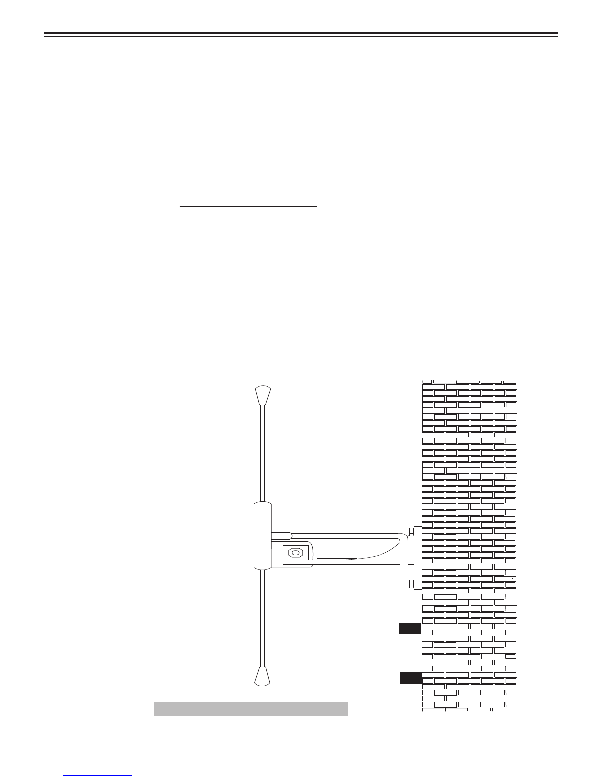
4.2 RANGE EXPANSION
The range and performance of this equip-
ment can be improved by the addition of more
efficient antennas.* These can be installed
either inside or outside the building and are
connected to the transmitter with 50 OHM
coaxial cable.
The center-fed half wave dipole, measuring
approximately 12 inches from tip to tip, will
provide excellent all round local signalling. It
is a light duty antenna suitable for sheltered
environments/internal installation (LUHFDP).
It includes a 15 foot cable.
NOTE: High frequencies can equate to
high power losses. Always use quality cable.
RG58 is only acceptable on cable runs of up to
5 meters (16.4 feet.) We recommend RG213,
or equivalent, on greater lengths. If in doubt
consult your dealer.
*Subject to license conditions. Specifically,
mounting height and Effective Radiated Power
(ERP).
4.3 IMPORTANT INFORMATION
It is the purchaser's responsibility to deter-
mine the suitability of this equipment and its
derivatives for any given application.
Good working practice dictates that a suit-
able system installation log must be generated,
together with a record of the dates when the
system has been manually checked, (with the
aid of signal strength meters, etc.) enabling the
system performance to be compared with the
original installation data.
4.4 SAFETY INFORMATION
These products are designed to operate
safely when installed and used according to
general safety practices. The following require-
ments should be observed at all times:
Do NOT subject this equipment to:
Mechanical shock
Excessive humidity or moisture
Extremes of temperature
Corrosive liquids
This equipment is designed for indoor use,
unless expressly stated otherwise, and must
not be used in classified Hazardous Areas,
including areas containing explosive or flam-
mable vapors, unless express authorization has
been given in writing by the manufacturer. If
in doubt, consult your local product dealer for
further information.
Do not obstruct any slots or openings in the
product. These are provided for ventilation to
ensure reliable operation of the product and to
protect it from overheating.
4.5 CARING FOR TRANSMITTER
Only use a damp cloth for cleaning (not
liquid or aerosol-based cleaners), and ensure
that any power is removed from the unit prior
to beginning the cleaning operation.
Removal of covers from the equipment must
only be undertaken by authorized service per-
sonnel, who must ensure that power is isolated
prior to removal.
4.6 LIABILITY
Scope and Microframe do not accept liability
for any damage or injury caused as the result of
misuse of this equipment. It is the responsibility
of the user to ensure that the equipment i s o p er-
ated in the manner for which it was intended,
and that it is the correct item of equipment for
the required task.
4.7 WARRANTY INVALIDATION
Alteration or modification to any part of this
equipment, without the prior written consent
of the manufacturer, will invalidate all manu-
facturer approvals and warranties. No adjust-
ments can be undertaken except by qualified
and licensed persons as defined by the FCC
Rules and Regulations. Operation of altered
equipment can result in fines, imprisonment,
and/or confiscation of such equipment.
4.8 SERVICE INFORMATION
If you experience a problem with your
equipment, please contact Microframe at 1-
800-635-3811.