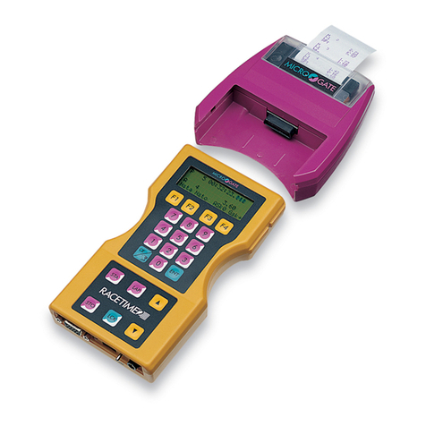
Microgate RACETIME 2 User manual

Microgate S.r.l.
Via Stradivari, 4
I-39100 BOLZANO - ITALY
RACETIME 2
User Manual
The Racetime 2 System
The Linkgate System
Single Start and Group Start Program
Simple Stopwatch Program
Release. 2.10

RACETIME 2 2
Index
THE RACETIME 2 SYSTEM.....................................................................................................6
1OVERVIEW ............................................................................................................................7
1.1 RACETIME 2 .................................................................................................................7
1.2 THE PRINTER ...............................................................................................................8
1.3 BACK VIEW ..................................................................................................................9
1.4 LINKGATE ENCODER...............................................................................................10
1.5 LINKGATE DECODER...............................................................................................11
1.6 CONNECTION BOX ...................................................................................................12
2CONNECTION DIAGRAMS..........................................................................................13
2.1 TIMING VIA CABLE ..................................................................................................13
2.2 TIMING VIA RADIO...................................................................................................15
2.2.1 Free along the Track............................................................................................... 16
2.2.2 Radio-Encoder-Gate Connection....................................................................... 17
2.2.3 Radio-Encoder-Photocell Connection............................................................. 17
2.3 TIMING VIA RADIO...................................................................................................18
2.3.1 Free along the track................................................................................................ 19
2.3.2 EncRadio – Gate Connection.............................................................................. 20
2.3.3 Radio-Encoder-Photocell Connection............................................................. 20
2.4 DISPLAYBOARD CONNECTION.............................................................................21
2.5 MEASURING SPEED..................................................................................................22
2.6 CONNECTING THE BATTERY CHARGER.............................................................23
2.7 CONNECTORS............................................................................................................24
2.8 CONNECTION CABLES.............................................................................................25
THE LINKGATE SYSTEM ......................................................................................................30
3INTRODUCTION.............................................................................................................31
4LINKGATE ENCODER : 3 FEATURES GUARANTEEING THE RELIABILITY OF RADIO
TRANSMISSION...........................................................................................................................32
4.1 DIGITAL TRANSMISSION OF IMPULSES..............................................................32
4.2 THE REPEAT FUNCTION..........................................................................................32
4.3 INTERNAL MEMORISATION OF EVENT TIMES..................................................32
5USING YOUR LINKGATE ENCODER........................................................................33
5.1 SELECTING THE CHANNEL ....................................................................................33
5.2 SELECTING THE TYPE OF SIGNAL........................................................................33
5.3 IMPULSE TRANSMISSION.......................................................................................33
5.4 THE REPEAT FUNCTION..........................................................................................34
5.5 CALCULATING A SPEED .........................................................................................34
5.6 HARDWARE RESETTING.........................................................................................34
5.7 RESETTING THE MEMORY .....................................................................................35
5.8 SYNCHRONIZATION.................................................................................................35

RACETIME 2 3
5.9 DOWNLOADING DATA onto RACETIME2.............................................................35
5.10 THE MODEM FUNCTION.........................................................................................36
5.11 MAINTENANCE.........................................................................................................36
PROGRAMS................................................................................................................................38
6INSTRUCTIONS FOR READING THE MANUAL.......................................................................39
7GENERAL INFORMATION ....................................................................................................40
7.1 FUNCTION AND CE KEY USE.................................................................................41
7.2 NUMERICAL DATA INPUT ......................................................................................41
7.3 SWITCHING ON THE MACHINE.............................................................................42
SINGLE START AND GROUP START PROGRAM............................................................44
8SINGLE START AND GROUP START MODES .......................................................................45
9MAIN MENUS ......................................................................................................................47
10 TIMING..........................................................................................................................48
10.1 INSERTION/CORRECTION FUNCTION.................................................................49
10.1.1 Start number insertion/correction...................................................................... 49
10.1.2 Finish number insertion/correction................................................................... 50
10.1.3 Use of keys
↑
↓
............................................................................................................ 50
10.1.4 Turning the Autoskip function on and off........................................................ 51
10.1.5 Skipped management (SkM)................................................................................. 51
10.1.6 Editing or displaying intermediate times........................................................ 52
10.1.7 Cancelling Skipped events memory................................................................... 52
10.1.8 Activation/disactivation of automatic assignment of finishes and
intermediate times on and off ............................................................................................. 52
10.1.9 Returning to the main menu ................................................................................. 53
10.1.10 Returning to the main menu during timing........................................... 53
10.2 MANAGEMENT OF EVENTS...................................................................................54
10.2.1 Displaying starts....................................................................................................... 54
10.2.2 Finishes management.............................................................................................. 55
10.2.3 Intermediate time management........................................................................... 57
10.2.4 Displaying speeds transmitted by the LINKGATE Encoder ................... 58
10.2.5 Display of average speeds..................................................................................... 58
10.2.6 LCK key use ................................................................................................................ 59
11 INTERPRETATION OF PRINTED DATA DURING TIMING...........................60
12 GROUP MANAGEMENT..................................................................................................62
12.1 RANKINGS FOR FINISH TIMES, INTERMEDIATE TIMES AND SPEED ..........64
12.1.1 Viewing on the screen............................................................................................. 65
12.1.2 Printing the ranking................................................................................................. 65
12.2 INTERMEDIATE TIME RANKINGS........................................................................66
12.3 SPEED RANKINGS ....................................................................................................67
12.4 PRINTING EVENT TIMES, NP, NF, DISQUALIFIED, SKIPPED..........................68
13 AUTOMATIC STARTS.............................................................................................69
14 DISQUALIFICATIONS/REINSTATEMENTS ......................................................70
15 SYNCHRONIZATION...............................................................................................71
16 OFF-LINE DATA TRANSMISSION........................................................................72
17 SYSTEM CONFIGURATION...................................................................................73
17.1 RACETIME configuration...........................................................................................73

RACETIME 2 4
17.1.1 Time display mode.................................................................................................... 73
17.1.2 Event times printout................................................................................................. 73
17.1.3 Automatic finish search.......................................................................................... 73
17.1.4 Net time print mode................................................................................................ 73
17.1.5 Maximum time............................................................................................................ 73
17.1.6 Measurement accuracy........................................................................................... 73
17.1.7 Modifying ‘dead’ times........................................................................................... 74
17.1.8 Activating the LCK key........................................................................................... 74
17.1.9 LINKGATE channel................................................................................................. 74
17.1.10 Setting of serial transmission parameters............................................. 75
17.1.11 Activation/disactivation of the printer and of acoustic signalling
when keys are pressed ........................................................................................................... 75
17.1.12 Initialization of configuration..................................................................... 75
17.2 SKITEST CONFIGURATION ....................................................................................76
17.2.1 ‘Radio’ speed base length..................................................................................... 76
17.2.2 ‘Average’ speed base length................................................................................. 76
17.2.3 Speed measurement unit......................................................................................... 76
17.2.4 Temperature and humidity probe tests............................................................. 77
17.3 DISPLAYBOARD CONFIGURATION .....................................................................78
17.3.1 Displayboard type..................................................................................................... 78
17.3.2 Displayboard number ............................................................................................. 78
17.3.3 Advertising................................................................................................................... 78
18 OTHER FUNCTIONS................................................................................................79
18.1 RECHARGING BATTERIES .....................................................................................79
18.1.1 Low batteries warning...................................................................................................... 80
18.2 MEMORY LIMITS......................................................................................................80
18.3 RECEIVING DATA FROM LINKGATE...................................................................81
19 RADIO SIGNAL QUALITY......................................................................................83
19.1 TIME CALCULATOR.................................................................................................84
SIMPLE STOPWATCH PROGRAM ......................................................................................86
20 SIMPLE STOPWATCH PROGRAM ......................................................................87
21 TIMING .......................................................................................................................89
22 SETTING INITIAL TIME (START TIME)............................................................91
23 VIEWING OF MEMORISED TIMES.....................................................................92
24 DISPLAY OF TIMES ON THE MICROGATE ALPHANUMERIC
DISPLAYBOARD....................................................................................................................92
25 DATA TRANSMISSION............................................................................................93
26 SYSTEM CONFIGURATION...................................................................................94
26.1 Racetime CONFIGURATION.....................................................................................94
26.1.1 Measurement accuracy........................................................................................... 94
26.1.2 Modifying ‘dead’ times........................................................................................... 94
26.1.3 LINKGATE channel................................................................................................. 94
26.1.4 Setting of serial transmission parameters...................................................... 96
26.1.5 Activation/deactivation of the printer and of acoustic signalling when
the keys are pressed................................................................................................................ 96
26.1.6 Initialization configuration................................................................................... 96

RACETIME 2 5
26.2 Setting the length for speed calculation........................................................................97
26.3 DISPLAYBOARD CONFIGURATION .....................................................................98
26.3.1 Displayboard type..................................................................................................... 98
26.3.2 Number of displayboards....................................................................................... 98
26.3.3 Advertising................................................................................................................... 98
27 OTHER FUNCTIONS................................................................................................99
27.1 RADIO SIGNAL QUALITY.......................................................................................99
27.2 time calculator ............................................................................................................100
27.3 Recharging batteries...................................................................................................101
27.3.1 Low batteries warning.......................................................................................... 102
APPENDIX................................................................................................................................105
28 TECHNICAL DATA ................................................................................................106
29 RACETIME2 TRANSMISSION PROTOCOL ....................................................................108
2.1 BINARY TRANSMISSION.......................................................................................108
29.1 ASCII TRANSMISSION...........................................................................................110
29.2 ON-LINE transmission during timing........................................................................112
30 DATA FORMAT FOR THE TRANSFER OF DATA STORED IN THE LINKGATE ENCODER113
30.1 HEADER....................................................................................................................113
30.2 DATA FRAME ..........................................................................................................113
30.3 SERIAL PORT SETTING .........................................................................................113
31 PROBLEMS AND REMEDIES ..............................................................................114

THE RACETIME 2
SYSTEM

RACETIME 2 – Linkgate System 7
1 Overview
1.1 RACETIME 2
1
2
3
4
5
6
7
8
9
10
11
Fig. 1
1. Alphanumeric display (4 lines, 20 colums) with a range width of –30 C +70 C
2. Function keys (F1,F2,F3,F4)
3. CE key (control/paper feed)
4. START key
5. STOP key
6. LOCK key
7. Arrow ↑↓ (running through times)
8. Case in ABS
9. LAP key
10. ENTER key
11. Numeric keyboard (0..9)

RACETIME 2 – Linkgate System 8
1.2 THE PRINTER
Ð
Ð
Ð
Inserting the
p
rinter
Fig. 2
Fig. 3 Fig. 4
Ó
ÓPress
ÏÏ
Opening paper roll compartment
The printer
Changing the paper
roll
Changing the printer
cartridge
Press to remove printing cartridge
Opening the printer compartment

RACETIME 2 – Linkgate System 9
2
3
4
5
6
1
Fig. 5
1.3 BACK VIEW
1. Case in ABS
2. 15 pole female CANNON panel connector
3. Red LED
4. Power point for battery charger
5. ON/OFF switch
6. 5 pole male panel connector

RACETIME 2 – Linkgate System 10
1.4 LINKGATE ENCODER
L
INKGAT
E
2ND
SYN RESE
SIGNAL REPEAT
E N C O D E R
SYNC RESET
SERIAL
CHANNEL
SHORT
IMPULSE
LONG
SIGNAL TYPE
MODEM
1
2
3
4
5
6
7
Fig. 6
1. SIGNAL key
2. SECOND FUNCTION (2ND) key
3. REPEAT key
4. MODEM key
5. Selector for transmitted signal type (Start, Lap, Stop)
6. Selector for transmitted signal redundancy (High, short signal – Low, long signal)
7. Selector for transmission channel (Dip Switch)
Fig. 7
Top
123
Bottom
4 5
1. SPEED input (RED banana jack)
2. GROUND (BLACK banana jack)
3. SIGNAL input (GREEN banana jack)
4. Power point for radio connection and serial data download
5. MODEM input (BLU banana jack)

RACETIME 2 – Linkgate System 11
1.5 LINKGATE DECODER
Fig. 8
2
1
Fig. 9
Bottom Top
3 4
1. Connection cable for Racetime2 (female 5 pole movable connector)
2. Loudspeaker
3. Cable output to connect with Racetime2
4. 3 pole male connector

RACETIME 2 – Linkgate System 12
1.6 CONNECTION BOX
1
9
8
7
6
5
4
3
2
Fig. 10
1. 15 pole female CANNON panel connector to connect to Racetime2
2. GROUND banana jack (COMMON)
3. START banana jack
4. 6 pole Amphenol connector for inputs (START, STOP, LAP, AUX)
5. STOP banana jack
6. 6 pole Amphenol connector for serial inputs/outputs
7. LAP banana jack
8. 6 pole Amphenol connector for analogic inputs and auxiliary outputs
9. AUX banana jack

RACETIME 2 – Linkgate System 13
2 CONNECTION DIAGRAMS
2.1 TIMING VIA CABLE
Gate and photocell connected to connection box with the photocell powered by Racetime 2
Connextion Box
Polifemo
Gate
Fig. 11

RACETIME 2 – Linkgate System 14
TIMING VIA CABLE
Gate and photocell connected to connection box with externally powered photocell
Photocell
Gate
Fig. 12

RACETIME 2 – Linkgate System 15
2.2 TIMING VIA RADIO
Taking data at finish
S
R
Gate
Linkgate
Photocell
Keep the
antenna in Microphone
a vertical
input (Mic)
position
Signal Type
on
“
0
”
(Start)
Keep the
antenna in
a vertical
position
Loudspeaker
Output
()
Volume at
approx 3/4
Linkgate Decoder
Fig. 13

RACETIME 2 – Linkgate System 16
2.2.1 Free along the Track
Taking data from anywhere along the track
Fig. 14

RACETIME 2 – Linkgate System 17
2.2.2 Radio-Encoder-Gate Connection
S
R
Fig. 15
2.2.3 Radio-Encoder-Photocell Connection
Fig. 16
S
R
Linkgate Encoder

RACETIME 2 – Linkgate System 18
2.3 TIMING VIA RADIO
Fig. 17 Keep the
antenna in
a vertical
position
Fig. 18
Gate
Linkgate
Signal Type
on
“
0
”
(Sta
rt)
Photocell
Linkgate DecRadio

RACETIME 2 – Linkgate System 19
2.3.1 Free along the track
Taking data anywhere along the track
Fig. 19

RACETIME 2 – Linkgate System 20
2.3.2 EncRadio – Gate Connection
Fig. 20
Gate
Linkgate
Keep the
antenna in
a vertical
position
Signal Type
on
“
0
”
(Start)
2.3.3 Radio-Encoder-Photocell Connection
Fig. 21
Linkgate
Other manuals for RACETIME 2
2
Table of contents
Other Microgate Measuring Instrument manuals
Popular Measuring Instrument manuals by other brands

Klemsan
Klemsan ECRAS 100-VCF instruction manual

Hanna Instruments
Hanna Instruments HI96715 instruction manual

JDS Uniphase
JDS Uniphase HST-3000 OLP-3057 user guide

Ralston Instruments
Ralston Instruments LC10 Series quick start guide

PCE Instruments
PCE Instruments PCE-T 260-ICA Operation manual

MEGAlink
MEGAlink ML2000 user manual