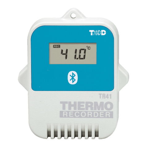
T&D TR-81 User manual

1999.12. 16004144020
Thank you for buying our product.
Please read carefully before using.
Copyright 1999 T&D Corporation. All rights reserved.
Instruction
Manual

Table of Contents
Replacing the Battery ・・・・・・・・・・・・・ 22
Troubleshooting・・・・・・・・・・・・・・・・ 23
Specifications ・・・・・・・・・・・・・・・・ 26
Guarantee and Warranty・・・・・・・・・・・・on back.
Safety Precautions and Instructions ・・・・・・・ 3
Software User Agreement ・・・・・・・・・・・ 5
What is Thermo Recorder TR-81 ?・・・・・・・ 6
Contents of Package ・・・・・・・・・・・・・ 7
Part Names and Functions ・・・・・・・・・・・ 8
Explanation of the LCD display ・・・・・・・・・ 9
Preparing the Thermo Recorder・・・・・・・・・ 11
Installing the Software ・・・・・・・・・・・・・ 13
Screen Names and Functions ・・・・・・・・・ 15
Notices about this User
s Manual
●Please read this manual carefully before using the product.
●This manual can not be reprinted, so please keep it in a safe place.
●We cannot guarantee nor or we responsible for safety if this product is used in any manner
other than was intended.
●Please follow the safety precautions carefully.
●Contents of this manual may be altered according to improvements made to the product
without notification.
●On screen messages in this manual may vary slightly from the actual messages.
●Figures in this manual may be slightly simplified and may differ from the actual product.
●Please notify us of any unclarities, mistakes or errors in this manual.
●Reproduction or use of any part or all of this manual is strictly forbidden.
●Please carefully read the guarantee and provisions for free repair.
●Microsoft and Windows are registered trademarks of Microsoft Corporation USA and are
binding in the USA and all other countries.
Company names and product names are trademarks or registered trademarks of each
company.
Starting to Record
・Start Recording Via Computer・・・・・・・・・ 17
・Start Recording Via Base Unit・・・・・・・・・ 19
Downloading Recorded Data ・・・・・・・・・・ 20
Saving Data ・・・・・・・・・・・・・・・・・ 21
CreatingText File ・・・・・・・・・・・・・・・ 21
Introduction
Getting Ready
Basic Usage
Other
FCC Compliance Statement for American Users
This device complies with Part 15 of the FCC Rules.
Operation is subject to following two conditions: (1) this device may not cause harmful interference. and (2) this
device must accept any interference received, including interference that may cause undesired operation.
NOTE: This equipment has been tested and found to comply with the limits for a Class A Digital Device, pursuant
to Part 15 of the FCC Rules. These limits are designed to provide reasonable protection against harmful interfer-
ence in a residential installation. This equipment generates, uses and can radiate radio frequency energy and, if
not installed and used in accordance with the instructions, may cause harmful interference to radio communica-
tions.
However, there is no guarantee that interference will not occur in a particular installation. If this equipment does
cause harmful interference to radio or television reception, which can be determined by turning the equipment off
and on, the user is encouraged to try to correct the interference by one or more of the following measures:
-- Reorient or relocate the receiving antenna.
-- Increase the separation between the equipment and receiver.
-- Connect the equipment into an outlet on a circuit different from that to which the receiver is connected.
-- Consult the dealer or an experienced radio/TV technician for help.
Warning
This equipment has been verified to comply with the limits for a Class A personal digital device, pursuant to Sub-
part B of Part 15 of FCC Rules. Only peripherals (computer input/output devices, terminals, printers, etc.) certified
or verified to comply with the Class A or B limits may be attached to this equipment. Operation with non-certified
or non-verified personal computer and/or peripherals is likely to result in interference to radio and TV reception.
The connection of a non-shielded equipment interface cable to this equipment will invalidate the FCC Certification
of this device and may cause interference levels which exceed the limits established by the FCC for this equip-
ment.
You are cautioned that changes or modifications not expressly approved by party responsible for compliance could
void your authority to operate the equipment.

4
●Condensation may occur if the unit is moved from one environment to another where the
difference in temperature is great.Use the unit in an environment where the ambient tem-
perature is from
-
10 to 60 ℃and the humidity is 90% RH or less.
●Do not leave the unit in direct sunlight or in excessively hot or humid places for long periods
of time. It may cause fire or otherwise cause the unit to malfunction.
●Do not expose the unit to harmful gases or chemicals.It may cause corrosion and / or other
danger to the unit and to people handling the unit.
●Exposing the unit to mechanical vibration may cause insufficient contact and data loss.
Make sure to place the unit in a steady environment.
●Avoid placing the unit in an area exposed to strong magnetic fields.
Safety Precautions and Instructions
3
Please follow these instructions carefully.
●This product has been designed for private or industrial use only. It is not for use in
situations where strict safety precautions are necessary such as in connection with
medical equipment whether directly or indirectly.
●We are not responsible for any malfunction or trouble caused by the use of our product
or by any problem caused by the malfunction of our unit. Please understand this before
using our product.
●Leakage of water or other foreign objects into the unit may cause fire or malfunctioning.
If something does leak into the unit make sure to remove the batteries immediately.
●Maintenance or modification of the main unit by anyone other than our authorized me-
chanics is strictly prohibited.This could lead to malfunctioning.
●Avoid smoke, steam, high humidity and dust.These could lead to malfunctioning .
●It is extremely dangerous to swallow batteries.Install and keep all batteries, sensors and
the Thermo Recorder Unit a safe distance from and out of the reach of small children.
●The Thermo Recorder is a device designed to measure and record temperature. Do not
use this unit for any purpose other than temperature measurement.
●The sensor may have a sharp edge, please take care when handling it.
Warnings
●Dropping the unit or exposing it to a strong impact may cause malfunctioning.
●If the batteries lose all power all recorded data and settings will be lost.Please make sure
to change the batteries before they lose power.
●Battery life varies depending on recording conditions and battery quality. Life may be shorter
than published.
●Battery terminals may provide insufficient contact due to age or vibration.This may lead to
data loss so please be sufficiently careful.
●If the unit will not be used for a period of time, for safety reasons please remove the battery.
They may leak and lead to malfunctioning.
●This unit is not waterproof. Do not use in an area where contact with water may occur.
Handling Precautions
Placement Precautions

Software (Hi for Windows )User Agreement
Escape Clauses
1.T and D Corporation shall not accept any responsibility for any damage whether direct
or indirect that results from the usage of Hi for Windows.
2.Specifications of Hi for Windows may be subject to change and service may be termi-
nated without advance notice to the user. In such a case T and D Corporation shall not
be responsible for any damages whether direct or indirect from the inability to use Hi for
Windows.
3.T and D Corporation has no obligation to correct any defects found in Hi forWindows.
4.T and D Corporation does not guarantee the operation of Hi for Windows.
Copyright
1.The Copyright for Hi for Windows, including the program and all relevant documents,
belongs solely to T and D Corporation.
2.Hi for Windows may be used free of charge and may be redistributed among friends or
acquaintances for noncommercial use without stipulation and in such cases the above
escape clauses will be effective for all users. For commercial reproduction see clause
three below.
3.The reprinting or redistribution for commercial purposes whether in part or in whole, in
magazines or as a part of any product is strictly forbidden without the expressed consent
of T and D Corporation. Any inquires concerning commercial redistribution should be
directed to the Sales Department ofT and D Corporation.
4.Please do not attempt to make any changes or modifications to Hi for Windows.
This product is a thermo recorder that makes use of a platinum resistance sensor to
measure and record temperature.Recorded data is then downloaded into a com-
puter using our special software where it can be easily displayed in table or graph
form.
What isThermo RecorderTR-81 ?
◆Designed to be used with a three wire Pt100 Temperature Sensor.
◆Measurement Range is from
-
200 to 600 ℃.
◆The unit has two separate channels for measuring and recording temperature.
◆Data capacity is 8,000 readings ×2 channels.
◆One Lithium Battery allows recording for 5
-
8 months.
Hi forWindows
By utilizing our special software you are able to download all recorded data into your
computer where it can be easily made into graphs and tables for printing, saving or
saving as text file data.
◆Can process and display up to 8 channels at the same time.
◆Can create a wide array of graphs with ease.
◆Can create a graph for a chosen period.
◆Automatically calculates and displays the highest and lowest values as well
as the average in graph or table form.
◆The text file data can be manipulated by all popular spreadsheet software.
65
※To use this software, Hi for Windows, you must use a computer that runs on
an MS-Windows Operating system (Windows 3.1 / 95 / 98 / NT 3.1 / NT 4.0)
and uses a Serial Communication Port (RS
-
232C).

8
Part Names and Functions
The Rear
The Side
7
The following items are included in the package.
1 Communication Cable
(RS
-
232C:D
-
SUB 9 pin)
1Thermo Recorder Unit
(TR-81) 1 Software disk
(Hi for Windows )
1 Lithium Battery 1 Attachment Plate
(1 screw)
Contents of Package
CR2
1 Instruction Manual //
//
/
Guarantee
Use the attachment plate to hang the
Thermo Recorder on the wall, etc.
How to use the Attachment Plate
LCD display
INTERVAL
Button
Power Switch
REC / STOP
Button Battery
Cover
Sensor Connection
Terminal
《Sensor Connection Terminal
ENLARGED》
Channel 2
Channel 1
Communication cable
jack
The Front

10
●RECORDING
The REC indicator comes on when recording is begun.It blinks while on
standby.The amount indicator marks increase as the data increases.
9
①①
①①
① …Recording Indicator.
②②
②②
② …Amount of Recorded Data.
Explanation of the LCD Display
①①
①①
①②②
②②
②③③
③③
③④④
④④
④
⑧⑧
⑧⑧
⑧⑨⑨
⑨⑨
⑨
⑤⑤
⑤⑤
⑤
⑥⑥
⑥⑥
⑥⑦⑦
⑦⑦
⑦
【DISPLAY】
●COMMUNICATING
The COM mark appears when communication is taking place between the
unit and your computer, i.e. when setting up recording, or downloading
data.
●BATTERY LIFEWARNING
The BAT message appears whenever the battery power is low. Record-
ing is still possible while lamp is on, but when blinking recording will be
discontinued. Please change the battery as soon as you see the warn-
ing lamp come on.
●FULL
The FULL mark appears when 8000 units of data have been recorded
in ONETIME Mode.This indicates that recording has stopped and it is
important to download the data into your computer as soon as possible.
●OVERTHE MEASURABLE RANGE
The Hi mark indicates that the temperature is over the measurable range
of 600℃.
●BELOWTHE MEASURABLE RANGE
The Lo mark indicates that the temperature is below the measurable
range of
-
200℃.
●SLEEP MODE
The battery lamp will begin to blink when power is very low, recording
will stop and the unit will automatically go into sleep mode.It is impor-
tant to change the battery before it begins to blink.
③③
③③
③ …Indicates communication in progress.
④④
④④
④ …Battery Life Warning.
⑤⑤
⑤⑤
⑤ …Displays Data Measurement for Channel 1.
⑥⑥
⑥⑥
⑥ …Displays Data Measurement for Channel 2.
⑦⑦
⑦⑦
⑦……
……
…Temperature Unit Display.
Display unit can be changed via. computer.
⑧⑧
⑧⑧
⑧SensorType (Pt100)
⑨⑨
⑨⑨
⑨Recording Mode
ENDLESS: When the recorded data goes over 8000 units the oldest data is
overwritten and recording continues.
ONETIME: When the recorded data reaches 8000 units the REC indicator goes off
and recording stops.
OneTime Mode…Changes to
FULL
and recording
stops.
Endless Mode…Indicates recording will continue.

12
33
33
3..
..
.
Turn Power On
●The back up power function ensures no data loss even if the power switch is
turned OFF.
②Connect Sensor to Terminal, making sure to follow directions on the sticker on
the backside of unit.(See figure below)
《Sensor ConnectionTerminal》
《Sticker on Backside》
【Sensor Wiring Figure】
Channel 2
Channel 1
A
(
red
)
B
(
white
)
B
(
white
)
S
A
(
red
)
B
(
white
)
B
(
white
)
ABB
●Usually all three wired platinum resistance sensors are wired as in
the figure below.Terminals are represented with the letters A / B or
color red / white.
③After connecting the sensor, tighten the screws to prevent slipping.
11
11
11
1..
..
.
Install the Battery
Preparing theThermo Recorder
①Using a coin, turn the battery cover lock as shown in figure 1 to open cover.
22
22
2
..
..
.
Connect the Sensor
①To connect the sensor, loosen the screws of the channel to be connected.
②Install Lithium Battery (CR2) as shown in figure 2.
● Use only new batteries.
● Make sure the battery is in the right direction.
③Turn the cover lock in the opposite direction of figure 1 to close cover.
《FIGURE 1 Backside of Main Unit》
《Backside of Main Unit》
《Backside of Unit Sensor ConnectionTerminal》
Channel 1
Channel 2
Screw

14
⑥⑥
⑥⑥
⑥After installation is completed a Hi for Windows Folder will be created and an
icon for [Hi for Windows] will appear in the Start Menu.
Open Hi for Windows by clicking on this icon. (See below)
⑤⑤
⑤⑤
⑤Check Copy to: if appropriate click OK to start copying.
13
Installing the Software
11
11
1..
..
.
Before beginning installation please check the following
◆Is Windows working properly ?
If Windows (3.1 / 95 / 98 / NT 3.51 / NT 4.0) is not activated properly, it may
be impossible to install and run Hi for Windows.
◆Quit all other applications.
If you are running other applications, make sure to quit them before installa-
tion.
22
22
2..
..
.
Install the Software
(
Hi forWindows
)
①①
①①
①Start Windows.(3.1 / 95 / 98 / NT 3.51 / NT 4.0)
②②
②②
②Place Software Disk in appropriate drive and open the [Win_eng] folder.
③③
③③
③Open SETUP.EXE .
④④
④④
④The dialog box ‘Setup: Hi forWindows’will appear.
※※
※※
※「C:
\
」represents the hard drive that Windows is installed in.If you want to
change the location please type in the desired drive and continue.

Data List Display
⑤⑤
⑤⑤
⑤Cursor Movement Button
By clicking the arrow buttons you can move the cursor or cursors together left or right. Only
operable for cursors which are activated
⑥⑥
⑥⑥
⑥Time and Date for Cursor at Point A and B,Time Gap between Point A and B,
Effective Calculation Range (Max. Min., Avg.)
⑦⑦
⑦⑦
⑦Channel Number Button
・By clicking a Number Button the display can be turned ON /OFF
・By dragging a channel button to another channel and dropping it the data will be moved to
that channel.
・By double clicking a channel button a dialog box will appear that will allow you to delete the
data or change the recording settings for that channel.
⑧⑧
⑧⑧
⑧Data Name, Recording Interval, Amount of Data, Data at Cursor A, Data at
Cursor B, Difference between A and B
⑨⑨
⑨⑨
⑨MaximumValue, MinimumValue, AverageValue,Temperature Unit
By double clicking the number value for Max or Min the display will move to that point on the
graph.
⑩⑩
⑩⑩
⑩Button for MovingVertical Axis
The Vertical Axis moves up or down by clicking these arrow buttons.
⑪⑪
⑪⑪
⑪Vertical Gauge Bar
Allows you to move across the whole range of data from the lowest value to the highest for all
eight channels.The colored bar represents the data presently displayed as a part of the total.
By dragging the gauge you can move up and down to the data you want to be displayed.
⑫⑫
⑫⑫
⑫Magnification andWidening Using the Mouse.
Magnification :With the left button drag the mouse to outline the area you want to
magnify.
Widening :By double clicking the right button the data area will be widened at a regular
interval to allow you to see a larger range.
This is a list of the data that was displayed in graph form.
MaximumValue is in RED, Minimum is in
BLUE, and Average is in PINK.
Scroll Bar: By dragging it up and down
you can move to the data you want.
15
Graph Display
①①
①①
①Horizontal Gauge Bar
Allows you to move across the whole range of data from oldest to newest for all eight channels.
The colored bar represents the data presently displayed as a part of the total. By dragging the
gauge you can move left and right to the data you want to be displayed.
②②
②②
②Menu Bar
Click the menu bar you want to display a pull down menu from which you can choose from an
array of commands.
③③
③③
③Button for Moving Horizontal Axis
The time axis moves by clicking these arrow buttons.
④④
④④
④A and B Cursor Buttons
Click and drag the A or B button to move the cursor left or right. By left clicking on the button
you can activate or disactivate the cursor movement function.
⑨⑨
⑨⑨
⑨
⑧⑧
⑧⑧
⑧
②②
②②
②
③③
③③
③
Screen Names and Functions
●This screen is only a representation for explanation purposes and may differ
from actual screen.
●For a detailed explanation of operations use the [Help] menu.
④④
④④
④
⑤⑤
⑤⑤
⑤
⑥⑥
⑥⑥
⑥
⑦⑦
⑦⑦
⑦
①①
①①
①
⑫⑫
⑫⑫
⑫
⑪⑪
⑪⑪
⑪
⑩⑩
⑩⑩
⑩
16

18
●Recording Interval…1/2/5/10/15/20/30 seconds,
1/2/5/10/15/20/30/60 minutes
●Recording Mode…One Time / Endless Loop
●Temperature Unit Displey…℃(Celsius)/°F(Fahrenheit)
●Sensor Type…Pt100
●Record Starting Date…Programmed / Immediate
There are two ways to begin the recording process.
●Using the Computer…You can set the day and time you want recording to start and can
set or change all recording functions via the software.
●Using the Buttons on the Main Unit…By pushing the REC button you can begin recording
immediately as well as set or change the recording
interval.
①Start「Hi for Windows」
②From the [Communication] Menu choose [Start Recording...]
③The following screen will be displayed from which all settings can be made.
④④
④④
④
Starting to Record
1.Connect the communication cable provided with the
unit to the serial port on your computer.The con-
nection cable is a D-SUB 9 pin female jack that
should be connected to the place with such a
marking.
2.Connect the cable to the Thermo Recorder main unit. Make sure it is con-
nected properly, pushing in until you hear a click.
17
●If you connect to the wrong place communication will not take place.Also make
sure that the cable is connected properly in the right position.
《Side view of main unit
Communication cable connection jack》
11
11
1..
..
.
Start Recording via Computer
3.Set the Recording Conditions.
Make sure that the date and time setting is correct on your computer. If it is not, the
data and time for all data recorded will be wrong. Once a Channel Name, Record-
ing Mode, Temperature Unit Display, and / or Sensor Type has been set those set-
tings will be saved, even if, the batteries loose power.
Caution
④By clicking [Setup] the settings will become active.The LCD Display on the
main unit will display a blinking REC until the set recording date and time
arrives.
●
When you want to stop the recording function simply click on the [Stop] button in
the [Recording Start] display in the [Communication] pull down menu.You can
cancel a programmed start in this same way.
●
When you want to check the recording settings go to the [Recording Start] dis-
play in the [Communication] pull down menu and click on [Present Settings] and
the present settings will be displayed.YOU CAN NOT CHANGETHE SETTINGS
WHILE RECORDING.

2019
1.Set the Recording Interval by pressing the [INTERVAL] button.Each time you
press, it will take you to the next possible interval.A pause of 3 seconds will
set the interval and return you to the main display.
2.Start Recording by pressing down on the [REC/STOP] button for more than 2
seconds;the REC lamp will appear lit on the display.
WARNING
●With some computer models, even though you have set a programmed start and
the unit is in waiting mode, by pressing [REC/STOP] recording will begin immedi-
ately.
●While recording, Recording will stop if you hold down the [REC/STOP] button for
more than 2 seconds.
●If you want to make any changes to the settings other than recording interval
please see [Start Recording Via Computer]
《10 seconds》《10 minutes》
If you press on the [REC/STOP] button when the REC lamp is not lit, the next
recording will begin and any former data will be automatically deleted.
22
22
2..
..
.
Start Recording via Base Unit
●When you want to stop a recording session press the [REC/STOP] button for 2
or more seconds.
●When you want to check the recording interval while recording press the [IN-
TERVAL]buttonand it will appear onthe display.YOUCAN NOTMAKE CHANGES
WHILE RECORDING.
①From the [Communication] menu select [Download Recorded Data...]
②The [Download Recorded Data] screen will appear.
③Start downloading by clicking [Download]
④After downloading has been completed click the [Exit] button and the corre-
sponding graph will be displayed.
Downloading Recorded Data
11
11
1..
..
.
Make sure Communication Cable is connected to the Com-
puter.
22
22
2..
..
.
Make sure Communication Cable is connected to theThermo
Recorder.
●For instructions on these steps, see page 17.
3.3.
3.3.
3.
Begin Downloading Data.
③③
③③
③④④
④④
④

2221
CreatingText File
Saving Data
Type in the desired name
in the [Untitled.TRH] space
under [File name].
Make sure to change [File Type] when necessary.
Specify location for saving
※Sample Screen
Make sure to change [FileType] when necessary.
・Text File (Comma)[,] ・Text File (Tab) ・Text File (Semi colon)[;]
・Text File (Space) ・All Files [*.*]
●●
●●
●Codes such as comma, tab, semicolon and space are used to divide cells when loading
text file through spreadsheet software such as Lotus 1,2,3 and Excel.
※※
※※
※Text File can not be loaded into Hi for Windows.
◆From the [File] Menu select either [Output All Data inText File...] or [Output Partial
Data inText File…]
※Sample Screen
Type in the desired name in
the [Untitled .TXT] space
under [File name].
Type of file is [.TXT]
Specify location for saving
◆From the [File] Menu select either [Save All Data As…] or [Save Partial Data As…]
Replacing the Battery
●The main unit can remain in working condition for about 2 minutes without a battery.
●Battery life depends on many conditions including the recording environment, the recording inter-
val, the amount of communication, the surrounding temperature, and others.This explanation is
based on using a new battery and in no way should be taken as a guarantee of battery life.
Recording Int. of more than
2 sec’s. Recording Int. of 1 second
Maximum 8 months Maximum 5 monthsTime before BAT lamp (warning) appears.
◆The following chart can give you a general idea as to battery life.
Time to change the battery
◆Once the BAT lamp appears on the display make sure to change the battery as soon as
possible. If you change the battery before the BAT lamp begins to blink, recording will
continue uninterrupted and without any loss of data.
◆If the batteries go completely dead, all recorded data and recording settings will be lost,
so please be attentive to the BAT lamp.
After changing the battery
◆If you changed the battery when the BAT lamp was on.
◆If you changed the battery when the BAT lamp was blinking.
Change battery Returns to same condition as before lamp
appeared. Recording continues without
trouble.
Change battery The power automatically goes off.Make
sure to turn back on.
If the BAT lamp is blinking make sure to download all data as soon as possible.If you
press the [REC/STOP] button on the main unit a new recording session will begin
and all previously recorded data will be automatically deleted.
WARNING

23 24
Troubleshooting
Q
::
::
:
I can’t get the communication cable connected to the computer.What should I do?
A:Please connect the communication cable provided with the Thermo Recorder into the
serial port of your computer (D-SUB 9 pin male connector). If for some reason you
can not connect directly, please use an appropriate adapter (gender changer plug)
as explained below.
・・
・・
・If the connector on your computer is a D-SUB 9-pin male then there is no need for
an adapter.
・・
・・
・If the connector on your computer is a D-SUB 25 pin female then use an adapter
(D-SUB 25 pin male to a D-SUB 9 pin male)
・・
・・
・If the connector on your computer is a Half pitch 14 pin female then use the adapter
(Half pitch 14 pin male to a D-SUB 9 pin male) or a combination (Half pitch 14 pin
male to D-SUB 25 pin male) and (D-SUB 25 pin female to a D-SUB 9 pin male).
Q
::
::
:
I can’t download settings and / or data from theThermo Recorder to my computer.
What should I do?
A:Check to make sure that the connection is proper.Communication will take place
only through the serial port (RS-232C) and will not work through the printer port or
any other.
A:Check to make sure that you can control the Thermo Recorder with the software.
A:Make sure that the serial port has been selected correctly in the [Communication]
pull down menu in the software. Please check which port you are connected to
(COM1-COM4) and select appropriately.
A:If you have access to another computer try to see if you can download using it.
A:If you have a computer with energy saving function settings, make sure that the serial
port has not been turned off.Especially on NEC brand PC98 notebook computers the
default setting may be such.
A:If your computer is a DOS/V type check to make sure that the serial port has not been
rendered unusable by the BIOS setting.
A:If your computer is Windows 95/98 please make sure that the serial port setting has
not been made to render it unusable.With many all in one computers it serves as the
modem jack.
Examples of various serial ports:
《
D-SUB 25 pin female
》《
D-SUB 9 pin male
》 《
Half pitch 14 pin female
》
《How to check》
①In Windows 95/98 Open the [System] file in the [Control Panel] (Figure 1).
《Figure 1 Control Panel》
《Figure 2 [Device Manager]》《Figure 3 [Port (COM&LPT)] enlarged view》
・To find out more details about the port in question you can double click on [!] to
open [Properties] and a window giving details about that port will appear.
②Open the [Device Manager] file in the [System Properties] window and double click
on [Port (COM&LPT)] (Figure2) to open. Check to see if [Com Port (COM1)] and/or
[Com Port (COM2)] are displayed.If so they should be usable unless they have a [!]
or a [x] (Figure 3) mark on them, If such a mark exists, that port is unusable.If you
can not use a communication port please contact your computer’s maker.
Figure 4 Case where modem is using Port (COM2)
A:If your computer has an internal modem, make sure that the communication port is
not being used by it. In some cases even though no settings appear for the commu-
nication port, it can not be used. Check to see which port is being used by the
modem.

25 26
A:Sometimes communication will not work if an extension cable has been added to the
communication cable or if a switch has been added to the serial port (RS-232C).
A:Check to see if some other communication software is in use.
A:Most desktop models have two serial ports, try changing the plug to the other port
and change the settings.
Q
::
::
:
The images are hanging off the display screen.What should I do ?
A:The display should be set at a resolution of 640x480 dpi or higher.
Q
::
::
:
The date and the time of the recorded data are different from the actual date and
time.What should I do?
A:The Thermo Recorder takes the date and time from your computer when it is set
up. Make sure that the date and time are correct on your computer.
Q
::
::
:
Is the data backed up automatically?
A:If the battery power goes low while recording the BAT lamp will come on. If the
power decreases even more, recording will be ceased and a backup of the re-
corded data will be made.
Specifications
Thermo RecorderTR-81
Recording Channels 2 Channels
Sensors Pt100 Three Wire Sensors
Measurement Range -200℃to 600℃
Measurement Reliability ±0.3℃(‑200〜80℃) ±0.5℃(80〜450℃)
(when main unit is at 20℃± 10℃) ±1.0℃(450〜600℃)
※No account for sensor differences related to sensor type.
Measurement Resolution 0.1℃
Measurement Current 1 mA
Starting Methods Immediate / Programmed (by computer only)
Recording Modes One Time / Endless Loop
Recording Intervals 1/2/5/10/15/20/30 seconds, 1/2/5/10/15/20/30/60 minutes
Battery 1 Lithium CR2 Battery
Battery Life Maximum 8 months
Display Temperature and Unit, Recording Settings, Battery Warning,
Amount of Data, Sensor Type and Recording Mode.
Data Capacity 8000 Readings x 2 Channels
Dimensions / Weight H123mm x W58mm x D33mm / 132 grams
Temp.and Humidity Resistance ‑10 to 60℃/90%RH (No condensation)
Software
((
((
(
Hi for Windows
))
))
)
Channels Displayed Up to 8 Channels simultaneously displayed / processed
Data Display Graph, Table, High and Low Temp., Average Temp.,
Recording Interval, Amount of Data Recorded.
Data Output Printed Graph, Printed Table, Text File
Control Functions Programmed Start, Recording Interval, and Mode Settings.
Other Accessories
Communication Cable 1 RS-232C: D-SUB 9pin cable 1.5 meters
Battery 1 Lithium (CR2)
Attachment Plate 1 (includes 1 screw)
User’s Manual 1 booklet
■Inquires about the Product
Sasaga 5652-169 Matsumoto City NAGANO 399-0033 Japan
Tel. +81-263-27-2131 Fax. +81-263-26-4281
Homepage address :http://www.tandd.co.jp/english
Other manuals for TR-81
1
Table of contents
Other T&D Measuring Instrument manuals
