manuals.online logo
Brands
  1. Home
  2. •
  3. Brands
  4. •
  5. Center
  6. •
  7. Measuring Instrument
  8. •
  9. Center 531 User manual

Center 531 User manual

531
LEDLIGHTMETER
CENTER TECHNOLOGY CORP.
4F, NO.415, Jung-Jeng Rd., Shu-Lin Dist., New Taipei City 238, Taiwan
E-Mail:center@centertek.com
http://www.centertek.com GCA000531-12000
Safety Information
n
o

M
i
t
a
c
n
u
r
u
t
a
s
l
n
I
Environment Conditions:
Introduction
Thank you for using our LED Light Meter. To ensure that you can get the
most from it, we recommend that you read and follow the manual carefully
before use. The Light Meter has been designed, manufactured, and
delivered under strict quality control criteria by a factory certified. This
meter has the following characteristic.
Read the following safety information carefully before attempting to operate
or service the meter.
Use the meter only as specified in this manual ; otherwise, the protection
provided by the meter may be impaired.
Ÿ Altitude up to 2000 meters
Ÿ Relatively humidity 90% max.
Ÿ Operation Ambient 0 ~ 40°C
Explanation of Symbols:
Comply with EMC.
When servicing, use only specified replacement parts.
Storage Temperature:
Dimension / Weight:
Accessories:
169(L)×63(W)×37(H)mm (6.7”×2.5”×1.5”)
Battery, instruction manual, carrying case.
-10 to 50°C (14 to 122°F)
Accuracy: ±3% rdg ±5 dgts (Standard A light source)
8% other visible light source
Temperature characteristics:
Response time: 0.5 sec
Light detector: SI Photodiode
Operation temperature: 0°C ~ 40°C(32°F ~ 104°F)
Operation humidity: 0~80% RH
Storage Humidity: 0 to 70% RH
Specifications
Measuring range: 0.0 to 199.9/1999/19990/199900 lx
0.00 to 19.99/199.9/1999/19990 fc
Automatic or manual selection of range
Resolution: 0.1 lx, 0.01 fc
Easy to use
Automatic zero
Automatic ranging
±0.1% / °C(25°C)
Over range: “-OL-” display
Power supply: 1.5V type AA battery x2
Power life: Approx. 80 hours
Weight: Approx. 210g
Repairs or servicing not covered in this manual should only be performed
by qualified personal.
Attention!
Periodically wipe the case with a dry cloth. Do not use abrasives or
solvents on this instrument.
Cleaning
Maintenance
Operating carefully, and do not drop the meter or hit it with a hard object.
Avoid using the meter in a dirty, dusty, or salt-air area or where there are
corrosive gases. If dirt or dust adhered to the surface of the detecting light,
will decrease accuracy of the measuring value to clean the surface by
wiping with a soft and dry cloth.
Precautions on handling
Symbol Definition & Button Location
1. LCD Display:
MAX/MIN function build in
Large backlight LCD display
Range indicator
Battery capacity
indicator
Minimum value
indicator
Maximum value
indicator
Auto power off
indicator
Illumination value
Set light source
mode indicator
Illumination Unit
indicator
Angledeviationfromcosine
characteristics
10° ± 1% 30° ± 2%
60° ± 5% 80° ± 20%
Value hold
indicator
Light source
correction value
choice indicator
LCD display:
6 1/2" large size back light LCD display.
Power button:
Push this button to turn on the meter. Push and hold this button for 3
seconds to turn it off. The unit will automatically turn itself off after 30
minutes if no key operation. To disable the automatic power off
function, turn the meter off, push and keep holding “ ” button, then
push power button to turn on. The “ ” will disappear from the LCD to
confirm this operation.
Backlight ( Power ) button:
Push this button to turn on and off the LCD backlight. The backlight will
be automatically off after 30 seconds to save battery power.
HOLD button:
The user may hold the present reading and keep it on the LCD display
by pressing the button. To release the data held operation, user
may press the button again.
Max Min button:
Push this button to set the meter working under MAX/MIN mode. By
pushing this button, the user may swap the LCD reading among
maximum, minimum and current reading. Push and hold this key for 3
seconds to exit MAX/MIN mode.
Range selector button:
The user may use this button to select the preferred measuring or
automatically selected by the meter. The available ranges are:
AUTO, 200, 2000, 20000, 200000 lx / AUTO, 20, 200, 2000, 20000 fc
Fc/lx selector button:
To switch the measuring unit between Foot Candle and Lux.
2
2. Name of Parts & Position: Lens Protecting Cover :
This is used to protect the
photo lance from scratching
and create complete dark
environment for the meter
to perform dark current
calibration. During power
on process, this cover
should be set properly in
front of the sensor lens,
otherwise an error message
will be shown on the LCD.
1
3
4
5
6
7
8
9
11
Characteristics of Sensor spectrum response
Light Sensing Probe:
Set button:
Press button, and use ▲ and ▼ to select a preset correction
setting from L0 to L8. According to the lighting source, the user should
set the appropriate preset correction for the accurate measuring result.
The user can set his correction factor if a high precision light meter
with “ V(λ) ” < 3% is available. The available setting are list bellow:
L0: Standard incandescent light source
L1: LED white daylight (5000K)
L2: LED AMBER (YELLOW) light (3000K)
L3: LED GREEN light
L4: LED RED light
L5: LED BLUE light
L6: Warm White Fluorescent Lamp (2700K)
L7: Cold White Fluorescent Lamp (6500K)
L8: user setup mode
Note: 1fc =10.76lx
This probe can be fixed on the meter parallel or perpendicular to
the LCD surface. Or it may be detached from the unit to fit the
measuring requirement.
Battery cabinet cover:
When battery capacity segment is
less than one, the user should
replace the battery. The battery
cabinet cover can be opened with a
Philips screw driver and two AA type
batteries should be installed.
10
* Operation:
Press the power button to turn on the power. Notice that covering the
light-detecting surface with the cap. “CAP-” will auto-appear on the LCD
display. After “CAL-” appears, the meter enters the automatic zero
adjustment. When automatic zero adjustment is completed, “CAL-”
disappears and “0.0” appears. After confirming the “0.0” display, remove
the cap to start measuring.
After the measurement has been completed, press the power button
again to turn off the power, and cover the light-detecting surface with
the cap for protecting against stray light.
Note:
If “ERR1” appears, check the cap to make sure it is on properly.
0.00
20.00
40.00
60.00
80.00
100.00
120.00
380 430 480 530 580 630 680 730
RelativeResponse(%)
Wavelength(nm)(%) CIE Photopic Curve Light Meter

This manual suits for next models

1

Other Center Measuring Instrument manuals

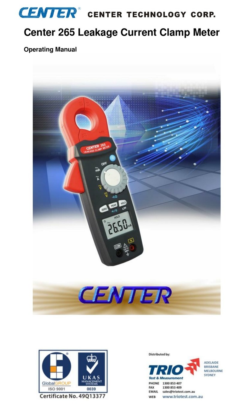
Center 201 User manual

Center

Center 201 User manual

Center 321 User manual

Center

Center 321 User manual

Center 265 User manual

Center

Center 265 User manual

Center 22 User manual

Center

Center 22 User manual

Center C315 User manual

Center

Center C315 User manual

Center 262 User manual

Center

Center 262 User manual

Center C325 User manual

Center

Center C325 User manual

Center 322 User manual

Center

Center 322 User manual

Center 327 User manual

Center

Center 327 User manual

Center 221 User manual

Center

Center 221 User manual

Center 320 User manual

Center

Center 320 User manual

Center 222 User manual

Center

Center 222 User manual

Center 251 User manual

Center

Center 251 User manual

Center C322 User manual

Center

Center C322 User manual

Center 212 User manual

Center

Center 212 User manual

Center 530 User manual

Center

Center 530 User manual

Center 340 User manual

Center

Center 340 User manual

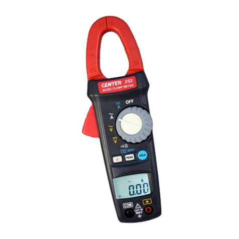
Center 252 User manual

Center

Center 252 User manual

Center 316 User manual

Center

Center 316 User manual

Center 32 User manual

Center

Center 32 User manual

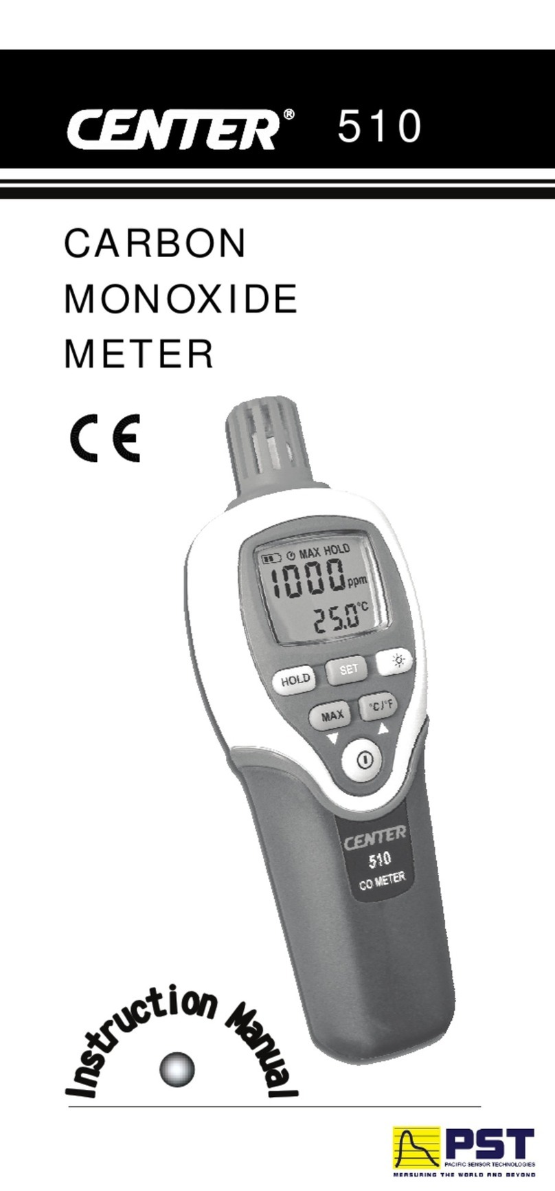
Center 510 User manual

Center

Center 510 User manual

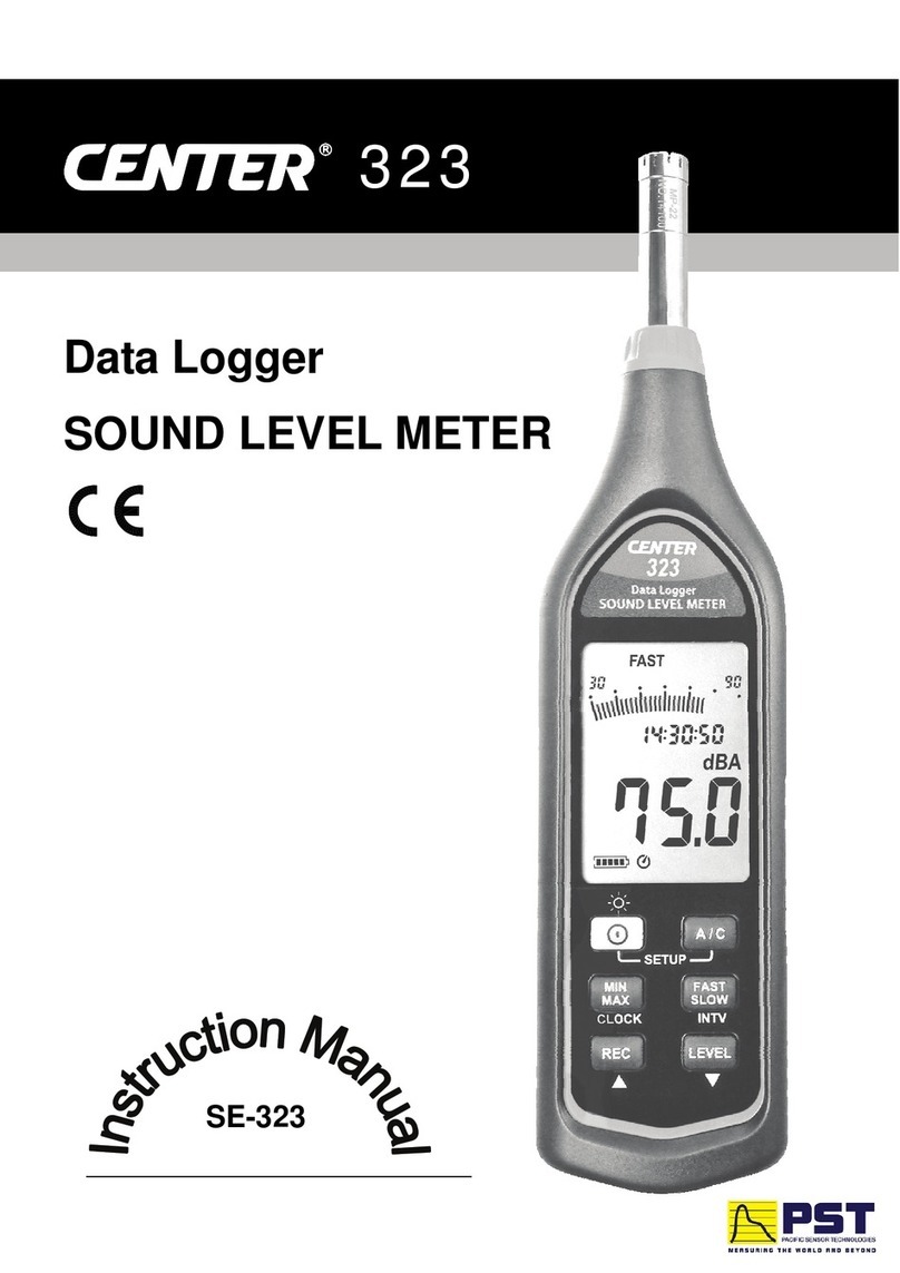
Center SE-323 User manual

Center

Center SE-323 User manual

Center 232 User manual

Center

Center 232 User manual

Center 342 User manual

Center

Center 342 User manual

Popular Measuring Instrument manuals by other brands

Endress+Hauser Dosimag operating instructions

Endress+Hauser

Endress+Hauser Dosimag operating instructions

Konica Minolta CR-14 brochure

Konica Minolta

Konica Minolta CR-14 brochure

G.R.A.S. 40HF instruction manual

G.R.A.S.

G.R.A.S. 40HF instruction manual

R&S FPC Series user manual

R&S

R&S FPC Series user manual

Rohde & Schwarz ZVT Series Getting started

Rohde & Schwarz

Rohde & Schwarz ZVT Series Getting started

Rohm Kionix KX134 Getting started

Rohm

Rohm Kionix KX134 Getting started

Tektronix PA1000 user manual

Tektronix

Tektronix PA1000 user manual

Siko SDE04 Original Installation Instructions

Siko

Siko SDE04 Original Installation Instructions

Sonel MPI-530-IT operating manual

Sonel

Sonel MPI-530-IT operating manual

Mountz EZ-TORQ III operating instructions

Mountz

Mountz EZ-TORQ III operating instructions

PCB Piezotronics 320C03 Installation and operating manual

PCB Piezotronics

PCB Piezotronics 320C03 Installation and operating manual

Isspro EV Installation instructions manual

Isspro

Isspro EV Installation instructions manual

Crane ProComm operating instructions

Crane

Crane ProComm operating instructions

Agilent Technologies 8720E Series Configuration guide

Agilent Technologies

Agilent Technologies 8720E Series Configuration guide

Lutron Electronics AQ-9901SD Operation manuals

Lutron Electronics

Lutron Electronics AQ-9901SD Operation manuals

SATO KEIRYOKI 1722-00 instruction manual

SATO KEIRYOKI

SATO KEIRYOKI 1722-00 instruction manual

Orbit Merret OM 402PWR manual

Orbit Merret

Orbit Merret OM 402PWR manual

WIKA intelliTHERM TGT70 operating instructions

WIKA

WIKA intelliTHERM TGT70 operating instructions

manuals.online logo
manuals.online logoBrands
  • About & Mission
  • Contact us
  • Privacy Policy
  • Terms and Conditions

Copyright 2025 Manuals.Online. All Rights Reserved.