Microlab, A Wireless Telecom Group Company, 25 Eastmans Road, Parsippany, NJ 07054
GPSR400 Quick Start Guide
US Model, 4-Channel Remote Outdoor Unit
Rev. 7
Unpacking and Inspection
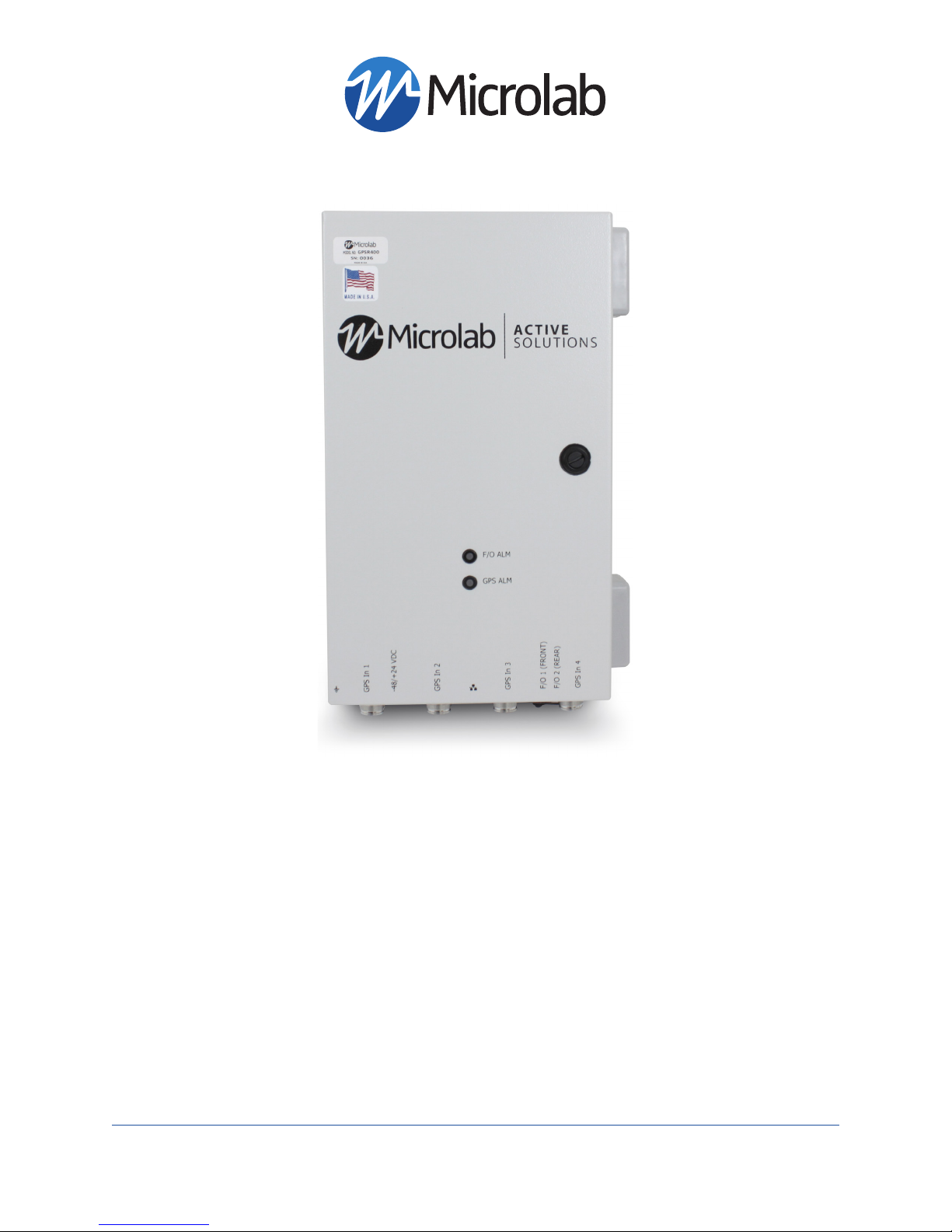
GPSR400 - Front and Bottom Panels
Note: Product appearance varies by model
Carefully unpack the GPSR400 remote unit
and check for damaged or missing parts. The
remote unit ships with the following:
• GPSR400 Remote Unit
• Two (2) 59” DC Power Cables
(Part#: 1-2273029-1)
• Quick Start Guide
Microlab’s digital GPS repeater system can be used for cellular communications UTC synchronization for locations
where the GPS signals are not readily available. The system is built with Microlab’s patent-pending Digital SkyTim-
ing Technology™ offering industry-first GPS signal transmission via CPRI for highly accurate timing and location. The
system offers several configurations for indoor and outdoor applications.
The GPS timing system is configured with indoor unit and outdoor unit. Both models sold sepately. Model GPSR400
is meant to work with Indoor Head-End Unit model GPSR116.
Introduction
Model Description
GPSR116 Indoor head-end receiver, 16 RF output, 1RU
GPSR400 Outdoor GPS signal transmitter, 4 antenna inputs, US version
Hardware Needed
The following items are recommended for Setup and opera-
tion:
• M10 Mounting Screws
• -48/+24VDC power supply with included power cable
OR Microlab GPSA003 AC/DC Adapter (not included)
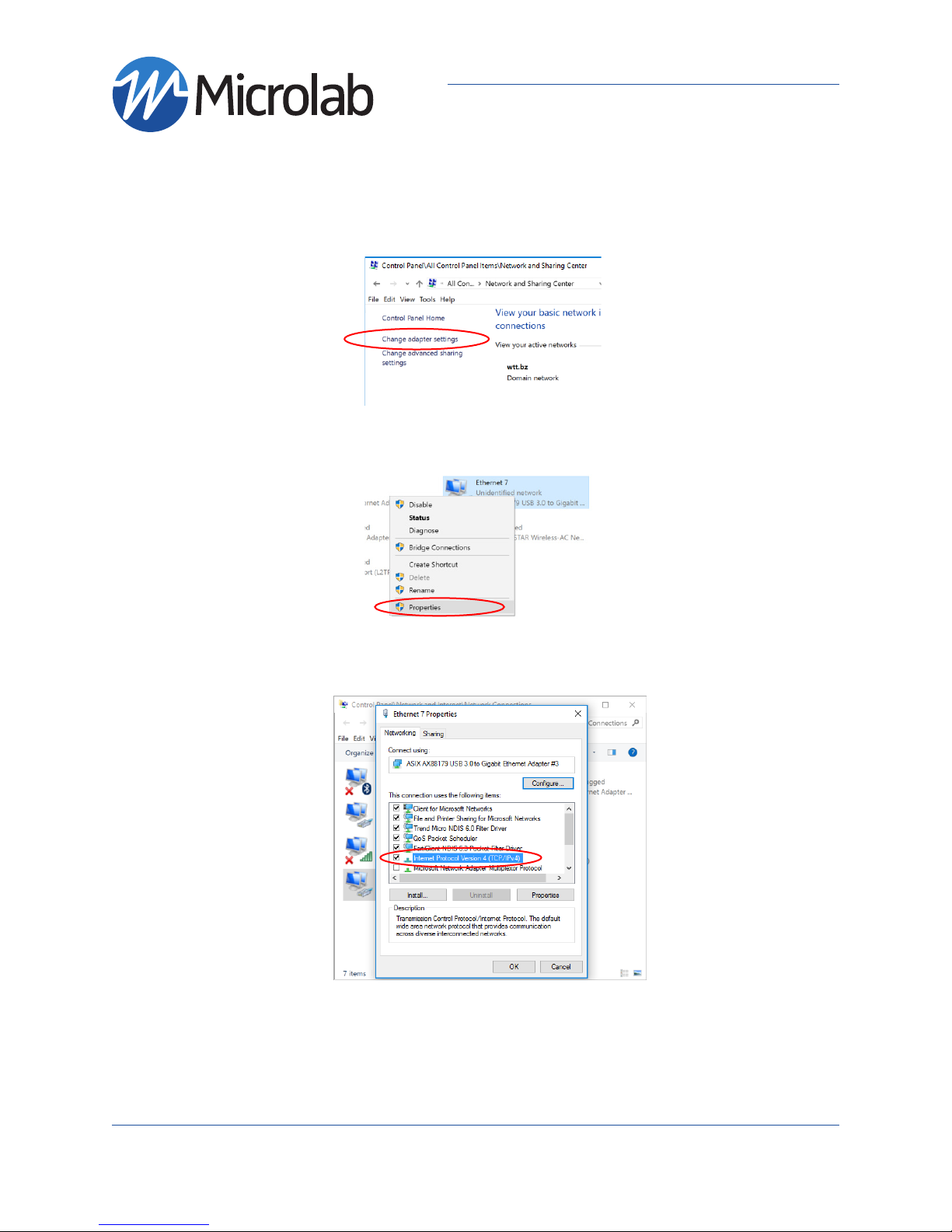
• One ethernet cable (RJ45 connectors)
• One PC or Laptop with an ethernet port or ethernet USB
adapter
• Singlemode duplex fiber < 2km in length
(with Duplex LC/UPC Interfaces)
Please contact Sales for other fiber length requirements.
GPS Repeater Models
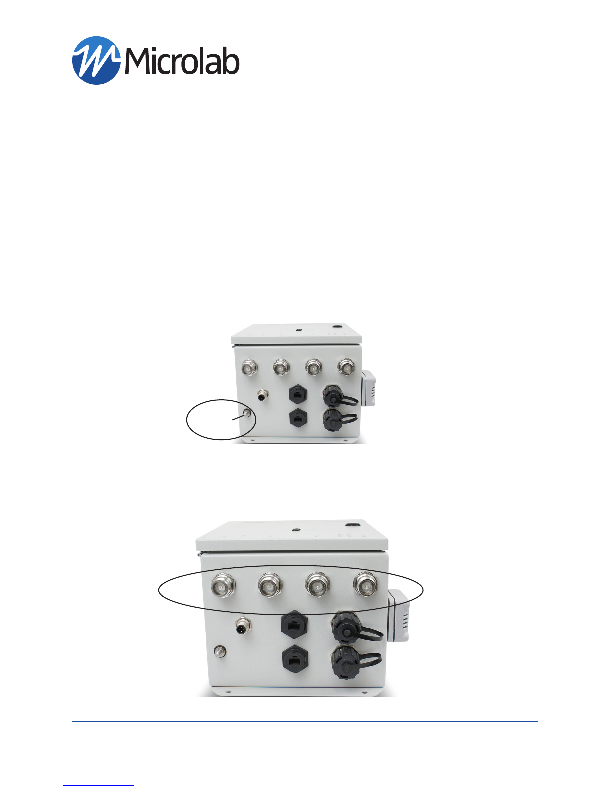
Service Locks
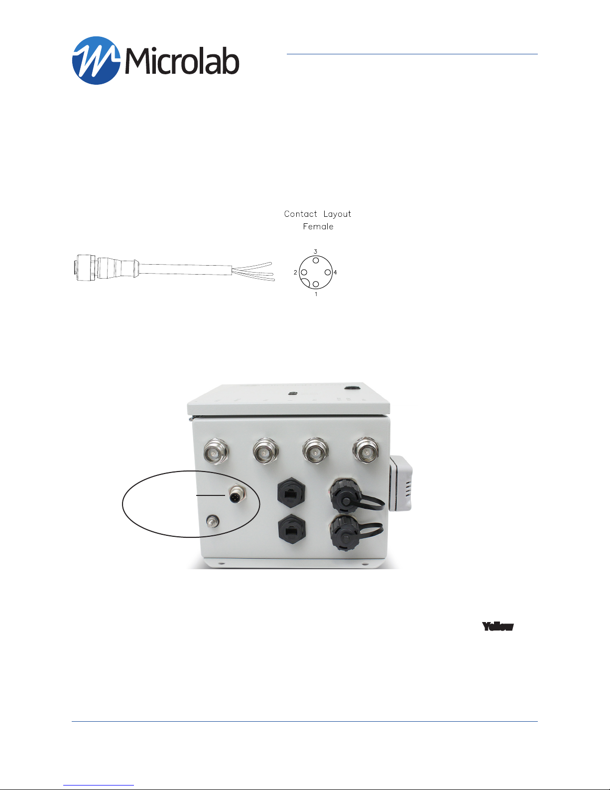
(M12) MALE
RECEPTACLE
DC POWER
GPS status
LED
OPTICAL ADAPTER,
LC/UPC DUPLEX,
SINGLEMODE
RJ45 CAT6
Ethernet
Ports
Ground
Nut
Antenna
RF Inputs
4.3-10 Female
Fiber status
LED