Microlectra Dinel DLS-27 Series User manual

Read carefully the instructions published in this manual before the rst use of the sensor. Keep the manual
at a safe place. The manufacturer reserves the right to implement changes without prior notice.
INSTRUCTION MANUAL
průmyslová elektronika
CapaCitive level sensors Dls–27
www.microlectra.nl
Microlectra bv.
Microlectra bv.
Augustapolder 12. 2992 SR Barendrecht. T he Netherlands.
www.microlectra.nl [email protected]


CONTENT
1. Brief ............................................................................................................................................5
2. Features of variants....................................................................................................................5
3. Dimensional drawings ................................................................................................................6
4. Mounting recommendation.........................................................................................................7
5. Range of application...................................................................................................................11
6. Electrical connection...................................................................................................................12
7. Sensor setting.............................................................................................................................13
8. Status signalization.....................................................................................................................14
9. Accessories ................................................................................................................................15
10. Order code................................................................................................................................16
11. Correct specication examples.................................................................................................16
12. Safety, protections, compatibility and explosion proof..............................................................17
13. Use, manipulation and maintenance ........................................................................................17
14. General conditions and warranty..............................................................................................18
15. Marking of labels ......................................................................................................................18
16. Specications ...........................................................................................................................20
17. FAQ (Frequently asked questions)...........................................................................................23

DLS–27 © Dinel
4
All operations described in this instruction manual have to be carried out by trained
personnel or by an accredited person only. Installation, commissioning, operation and
maintenance of the capacitive level sensors has to be carried out in accordance with this
instruction manual; the provisions of regulations in force regarding the installation of
electrical equipment have to be adhered to.
Improper use, installation or set-up of the sensor can lead to crashes in the application,
(overlling of the tank or damage of system components).
The manufacturer is not responsible for improper use, loss of work caused by either
direct or indirect damage, and for expenses incurred at the time of installation or during
the period of use of the level sensors.
Safety
Packing, tranSPortation and Storage
Equipment DLS–27 is packed in a polythene bag and the whole consignment is placed in a card-
board box. The cardboard box is suitably lled to prevent mechanical damage during transport. Let
the device packed up till the use to prevent possible damage.
Transport to the customer is realized by forwarding company. Upon receipt, please check whether
the shipment is complete and corresponds to the extent of the order, or whether during the transport
did not occurred the damage of the packaging or the equipment. The device apparently damaged
during transport do not use and contact the manufacturer to resolve the situation.
If the device is transported further, then only wrapped in the original packaging and protected
against shocks and weather. Store the device in its original packaging in a dry place, sheltered from
the weather, with humidity up to 85% without the effects of chemically active substances. Storage
temperature range is from -10 °C to +50 °C.
Sensor variants DLS–27_–20, 21, 22, 30 with the electrodes longer than 100 mm are tted
with protective caps at the ends of the electrodes to prevent damage of the electrodes,
box rupture or injury of handling persons. Before commissioning, remove the caps.
USed SymbolS
To ensure maximum safety of control processes, we have dened the following safety instructions
and information. Each instruction is labeled with the appropriate pictogram.
Alert, warning, danger
This symbol informs you about particularly important instructions for installation and op-
eration of equipment or dangerous situations that may occur during the installation and
operation. Not observing these instructions may cause disturbance, damage or destruction
of equipment or may cause injury.
Information
This symbol indicates particularly important characteristics of the device.
Note
This symbol indicates helpful additional information.

5
© Dinel DLS–27
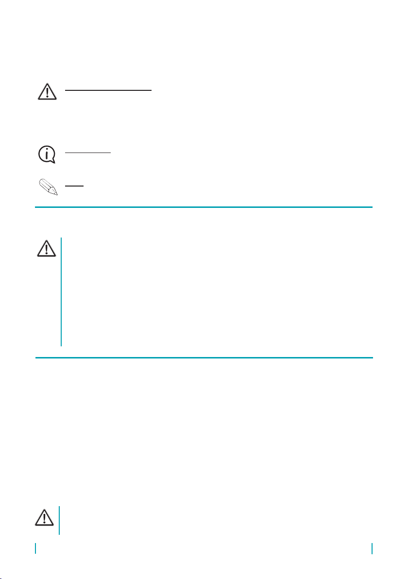
2. featUreS of variantS
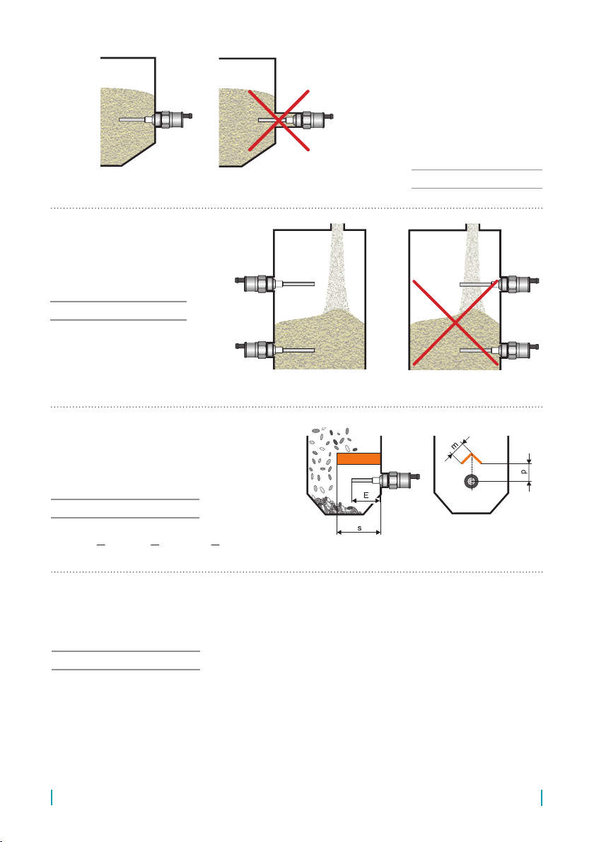
DLS–27_–10 Uncoated short bar electrode for sensing non-adhesive bulk-solid (powder)
materials (sand, sugar) and electrically non-conductive liquids (oils, diesel,
petrol), horizontal mounting. Electrode length 50 mm or 100 mm.
DLS–27_–11 Fully coated short bar electrode (PTFE – Polytetrauoroethylene) for
sensing electrically conductive liquids (water). Assembly into a side wall of
vessel or into a pipe. Electrode length 30 mm.
DLS–27_–20 Semi-coated rod electrode (FEP – Tetrauoroethylene-Peruoro-Propylene)
for sensing light-bulk solid or powder materials (plastic granulates, our,
cement) and non-conductive liquids (plant oils), horizontal, slant or vertical
mounting. Electrode length from 0.1m to 1 m.
DLS–27_–21 Fully coated rod electrode (FEP)
for sensing electrically conductive liquids (water solutions, water), adhesive
and aggressive materials, horizontal or vertical mounting.
Electrode length from 0.1m to 1 m.
DLS–27_–22 Fully coated rod electrode (PFA – Peruoroalkoxy) for sensing electrically
conductive liquids (water solutions, water), adhesive and aggressive
materials, horizontal or vertical mounting. Electrode length from 0.1 m to 1 m.
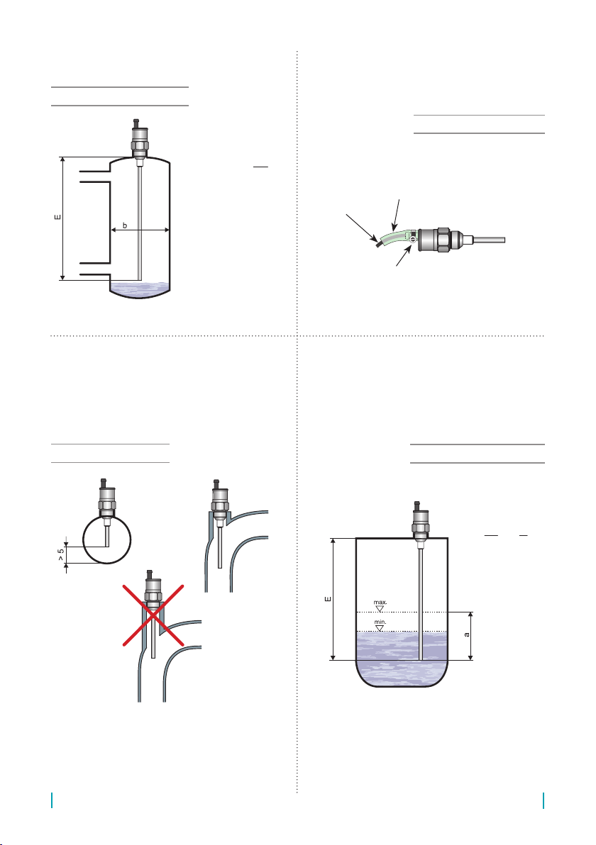
DLS–27_–30 Dismountable rod uncoated electrode for sensing bulk-solid (powder)
materials and conductive or non-conductive liquids. Mounting from the top
(vertically) or slant from the side. Electrode length from 0.1m to 3 m.
DLS–27_–31 Fully coated rod electrode for sensing aggressive electrically conductive
liquids (water, solutions of chemicals), vertical mounting.
Electrode length from 0.1m to 2 m.
DLS–27_–40 Uncoated stainless steel rope electrode and weight for general purpose in
deeper silos (bulk-solid and powder materials sensing – sand, gravel,
cement) or hoppers (liquids sensing), vertical mounting.
Electrode length from 1m to 6 m.
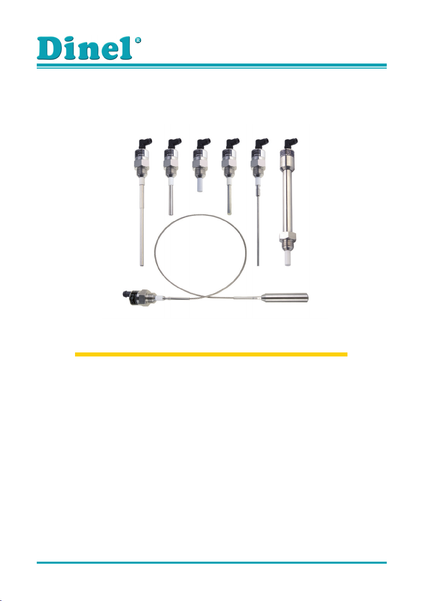
1. brief
Capacitive level sensors (switches) DLS®are designed for limit level sensing of liquids, bulky solid
and powder materials in vessels, containers, silos, tanks, reservoirs, etc. Sensors are made in
several modications of sensing electrodes – short and long rods or rope. The electrodes can be
coated what has important sense in case of adhesive, aggressive or electrically conductive media
sensing. The process coupling at the housing can be with thread M27x2, M30x1.5, G3/4” or with
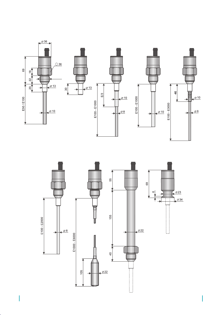
Tri-clamp coupling. Electric connection is provided by means of permanent cable lead (variant B)
or by means of connector (variant C). Output performances – transistor outputs with open collector
(NPN, PNP) or NAMUR output.
There are next performances available: N– For normal atmospheres; Xd – For use in ammable
dust atmospheres; Xi – Explosion proof – intrinsically safe for hazardous (explosive) areas and
XiM – Explosion proof – intrinsically safe for use in mines with methane or ammable dust pres-
ence danger (see technical specications). There are high temperature performance NT, XiT, XiMT
available.

DLS–27 © Dinel
6
3. dimenSional drawingS
DLS – 27_ – 10 DLS – 27_ – 11 DLS – 27_ – 20 DLS – 27_ – 21, 22 DLS – 27_ – 30
DLS – 27_ – 31 DLS – 27_ – 40 High temperatures
variants
Tri-clamp process
coupling
Thead *
* Type of threads: G 3/4''
M27x2
M30x1,5

7
© Dinel DLS–27
4. moUnting recommendation
DLS level sensors can be xed in a vertical, horizontal or bevelled position into the shell of the ves-
sel, the storage tank for the xation console in the pit, by screwing into the welding ange, using a
xing nut or TriClamp® process connection.
Basic application recommendations are mentioned below.
If the sensors are tted with protective caps at the ends of the electrodes, remove the
caps before commissioning.
In the case of vertical mounting it is recommended to
keep the mentioned distances applied to the length of the
electrode (the longer one).
All vertically mounted sensors
mm20050h
E
3
2
m
E
4
3
p
E
3
4
s
E
3
1
E
10
1
a
20
E
40b
50
E
10c
40
E
40d
20
E
20k
÷=
≈
≈
≈
÷≈
+≥=
+≥=
+≥=
+≥=
mm20050h
E
3
2
m
E
4
3
p
E
3
4
s
E
3
1
E
10
1
a
20
E
40b
50
E
10c
40
E
40d
20
E
20k
÷=
≈
≈
≈
÷≈
+≥=
+≥=
+≥=
+≥=
mm20050h
E
3
2
m
E
4
3
p
E
3
4
s
E
3
1
E
10
1
a
20
E
40b
50
E
10c
40
E
40d
20
E
20k
÷=
≈
≈
≈
÷≈
+≥=
+≥=
+≥=
+≥=
E – Electrode length in mm
During assembly into the metal tank or the storage tank, it is not necessary to separately ground the
base of the level sensor. In the case of installation in concrete tanks or silos, it is recommended to
install a level sensor on the auxiliary metal construction (console, cap, etc.) and to then connect it
using a permanently dipped metal item or with steel reinforcement in the concrete (armouring).
In the case of the reading of an aggressive medium, we recommend that the producer be consulted.
Fig. 1: Vertical mounting
Variants “C”
with connector
Variants “D”
with cable outlets
Variants “B”
with cable outlets

DLS–27 © Dinel
8
Fig. 3: Side wall mounting
mm20050h
E
3
2
m
E
4
3
p
E
3
4
s
E
3
1
E
10
1
a
20
E
40b
50
E
10c
40
E
40d
20
E
20k
÷=
≈
≈
≈
÷≈
+≥=
+≥=
+≥=
+≥=
mm20050h
E
3
2
m
E
4
3
p
E
3
4
s
E
3
1
E
10
1
a
20
E
40b
50
E
10c
40
E
40d
20
E
20k
÷=
≈
≈
≈
÷≈
+≥=
+≥=
+≥=
+≥=
mm20050h
E
3
2
m
E
4
3
p
E
3
4
s
E
3
1
E
10
1
a
20
E
40b
50
E
10c
40
E
40d
20
E
20k
÷=
≈
≈
≈
÷≈
+≥=
+≥=
+≥=
+≥=
E – Electrode length in mm
Fig. 4: Protective roof mounting
Protective roof mounting is recom-
mended when vertical movement of mate-
rial could damage the sensing electrode
(abrasive materials, blocks creating solid
materials, etc.)
For DLS–27_–10 and DLS–27_–20
Fig. 2: Long tting tubes in side wall mounting
In the case of side wall mount-
ing it is necessary to avoid long t-
ting tubes, where could the rests
of sensed media cumulate – see
the right gure. We recommend to
mount the sensor so that the whole
sensing electrode is inside the con-
tainer (vessel).
All from side mounted sensor
In the case of side wall mount-
ing it is necessary to place the
sensor aside the falling material
(liquid or solid).
All from side mounted sensors
In the case of slant wall mounting it is necessary to eliminate long ttings and reduce the media
sedimentation. The wrong example is in the middle gure. Left gure – appropriate mounting on the
auxiliary vertical plate. In some cases is allowed the variant shown on the right gure – but only for
DLS–27_–10 type, and only for not blocking materials.
For DLS–27_–10 and DLS–27_–20

9
© Dinel DLS–27
h = 50 ... 200 mm
Conductive probe
CNP–18
Electrically connect
Auxiliary plate
electrode
PDE-27
Fig. 7: Vertical installation for non-conductive
uids
E2 = E1+50
E1, E2 – Electrode length in mm
Fig. 6: Auxiliary electrode in non-conductive tanks
!
Fig. 5: Slant wall mounting
DLS–27_–10
For DLS–27_–20, 21, 22, 30, 31
When the environmental conditions (wind, rain,
snow) are present, we recommend to use types
with insulated electrode (21 or 31).
max.
min.
E
a
b
k
d
m
p
s
E
h
> 5
E1
E
E
c
E2
In the case of the application of the sensor in an electrically non-conductive (e.g. plastic) vessel
in the vertical position, then for the correct function, it is recommended to connect the housing of
the level sensor with an auxiliary electrode. The auxiliary electrode can consist of a bar which is
permanently dipped into the medium (e.g. conductive probe CNP–18), or can be use the auxiliary
plate electrode (PDE-27), where the rst part has thread for install of the sensor and the second part
is installed from the side on the wall into the area for the expected switching of the level sensor. Both
parts of PDE-27 are connected by steel wire. The area of the plate auxiliary electrode is a minimum
200 cm2. For non-conductive liquids, the only variation possible is with the plate auxiliary electrode
and in this case it is necessary to place the level sensor to prevent the movement of electrodes and
the axis is at the distance of lmax = E1/10, lmin = 20 mm.
In the case of vertical installation for level
sensing of unknown liquid (conductive and
non-conductive) in tanks or sumps is useful to
bend the end of electrode to right angle. The bend
the end of electrode increases locally sensitivity
and accuracy of level sensing.
For DLS–27_–30

DLS–27 © Dinel
10
mm20050h
E
3
2
m
E
4
3
p
E
3
4
s
E
3
1
E
10
1
a
20
E
40b
50
E
10c
40
E
40d
20
E
20k
÷=
≈
≈
≈
÷≈
+≥=
+≥=
+≥=
+≥=
Mounting in a bypass measuring tube. We
recommend to keep the tube diameter.
For: DLS–27_–20, 21, 22, 30, 31
Fig. 8: Bypass measuring tube
In the case of vertical mounting in outer are-
as or in the case of high mechanical exertion
we recommend to install protective hose on
the cable.
All sensors with cable outlets
Cable
PVC hose ϕ15/10 mm
Hose clip
Fig. 9: Protective hose install
In the case of mounting in the pipe it is nec-
essary to provide the minimum distance of
the inner walls from the electrode at 5 mm.
In some cases (sticky uids, low permittiv-
ity liquids) it is better to mount the sensor to
pipe bend.
For DLS–27_–10, 11, 21, 22
In the case of vertical mounting it is possible
to use hysteresis setting for simple two
state regulation (pump control). The height
of the controlled level is done by sensitivity
setting, the gap between the min. and max.
is dened by hysteresis.
For DLS–27_–20, 21, 22, 30, 31
mm20050h
E
3
2
m
E
4
3
p
E
3
4
s
E
3
1
E
10
1
a
20
E
40b
50
E
10c
40
E
40d
20
E
20k
÷=
≈
≈
≈
÷≈
+≥=
+≥=
+≥=
+≥=
E – Electrode
length in mm
Fig. 10: Mounting in the pipe
Fig. 11: Two state regulation by hysteresis
setting
E – Electrode length in mm

11
© Dinel DLS–27
E – Electrode
length in mm
5. range of aPPlication
DLS–27_–10
Is produced in two versions – with 50 mm or 100 mm length electrode. Short version (E50) is suitable
for clean non-conductive liquids level sensing (oils, diesel, petrol, etc.). Longer version (E100) is de-
signed for non-adhesive bulk-solid or non-adhesive powder materials (plastic granulates, sand, sugar,
grains, etc.) and other non-conductive liquids (lubricants, plant oils). Sensor is specied to be mount-
ed directly into a vessel or container wall (horizontal position) by means of welding ange or stainless
steel xing nut. In case of level sensing of low-permittivity media in non-conductive containers it is
recommended to mount the sensor on auxiliary metal-plate electrode with min. 200 cm2area.
DLS–27_–11
Is specied for limit level sensing of electrically non-adhesive conductive liquids (water and water
solutions). It is possible to use it for detection of boundary between different permittivity liquids (e.g.
water – oil). Sensor is mounted directly into the side wall of the vessel or in a pipe (horizontal posi-
tion) by means of normal or stainless steel welding ange.
DLS–27_–20
Is designed for limit level detection of light-bulk solid materials (plastic granulates) or powder ma-
terials (our, cement, limestone powder, detergents, etc.) and for materials with variable humidity
(feeding mixtures, wood sawdust, etc.). It is possible to use it for non-conductive uids with up to 2%
of water (plant oils, liquid propane, etc.). The sensor with electrode longer than 300 mm is recom-
mended to mount in vertical position only. Sensor is mounted directly into a vessel or container wall
in horizontal (up to E300), slant or vertical position by means of welding ange or stainless steel
xing nut. We should minimize the hollow spaces between the electrode and the wall where the
material can sediment (see application notes). In case of level sensing in non-conductive containers
it is recommended to mount the sensor on auxiliary metal plate electrode with min. 400 cm2area.
DLS–27_–21, 22
Is specied for conductive liquids level sensing (water, water solutions, mud, etc.). It is designed
for horizontal (up to E300) or vertical installation directly in the wall of a vessel. It reacts on partial
or full immersion of the electrode (dependent on adjusted sensitivity). The less is the sensitivity the
better is resistance to an adhered rests of media. Sensor is mountable directly into wall of a vessel
in horizontal or vertical position by means of welding ange.
In the case of vertical mounting it is necessary
to avoid long tting tubes, where could the
vapours condense or some rests sediment.
right gure – wrong, left gure – appropri-
ate. The similar situation is when the sensing
electrode goes through the concrete ceiling of
the silo. The hole diameter should be at least
50 mm (acc. to the thickness of the ceiling).
All vertically mounted sensors
Fig. 12: Long tting tubes in vertical mounting

DLS–27 © Dinel
12
6. electrical connection
Sensor with NPN or PNP output is allowed to lead only by resistive or inductive lead. Positive sup-
ply voltage (+U) is connected to the brown conductor BN (1), negative (0 V) to the blue conductor
BU (3) and the leads (only NPN or PNP type of output) to the black conductor BK (4). The capacity
loads and low resistance loads (bulb) is evaluated by the sensor as short circuit.
Version Xd is manufacture only with xing cable (variants “D” with cable outlets). The end of this
cable must be in terminal box with protection class IP6x.
For “B” and “D” variants with the xed cable, the individual colour cores of the connecting cable are
connected to the respective terminals of the related equipment (supply unit) see Fig. 13 to 15.
For “C” variant with the connector, the cable can be supplied with the sensor (length 2 or 5 m), tted
with the pressed connector socket or dismountable connector socket without the cable (see acces-
sories). In this case the cable is connected to the inside pins of the socket according to Fig. 16.
The sensor with related equipment is interconnected by a suitable three-core (N and Xd variations)
or two-core (Xi, XiT, XiM, XiMT variations) cable. The length of the cable for the Xi, XiT, XiM, XiMT
variations must be selected with respect to the maximum permitted parameters (usually inductance
and capacity) of the outside intrinsically safe circuit of supply units (NSSU, NDSU, NLCU). If using
a dismountable connector socket, the outside diameter of the cable is a maximum of 6 mm.
DLS–27_–30
Is designed for universal use in vertical position for limit level detection of liquids (conductive and
non-conductive) and bulk-solid and powder materials. It is not recommended to install the sensor
into closed vessels where intensive condensation occurs. Electrically conductive liquids are sensed
just by touch of the end of electrode. To react to non-conductive liquid or solid material it is neces-
sary 5 ÷ 20% dip into a medium dependently on the permittivity of sensed medium and set sensi-
tivity. Sensor is mounted directly into a tank, vessel, container or basin in slant or vertical position
by means of welding ange or stainless steel xing nut. In case of level sensing of low-permittivity
media in non-conductive containers it is recommended to mount the sensor on auxiliary metal-plate
electrode with min. 500 cm2area.
DLS–27_–31
Is designed for limit level detection of conductive liquids (water and solutions of chemicals). It is
possible to install the sensor into closed vessels, tanks, basins, etc. The sensor reacts to liquid level
after 2 ÷ 20% dip into a liquid dependently on the permittivity of sensed medium and set sensitivity.
Sensor is mounted directly into a vessel, tank or open basins in vertical position by means of weld-
ing ange or xing nut. When installed into an open basin it is necessary to ground the housing of
sensor or to connect it with sensed liquid. For this purpose it is possible to use any metallic ever
immersed object (pipe, etc.).
DLS–27_–40
Is specied for versatile use for limit level detection of liquids (conductive and non-conductive) and
bulk-solid and powder materials in depths down to 6 m. It is not recommended to install the sensor
into closed vessels where intensive condensation occurs. Electrically conductive liquids are sensed
just by touch of the end of electrode. To react to non-conductive liquid or solid material it is neces-
sary 5 ÷ 20% immersion into a material. Sensor is mounted directly into a vessel, tank or open ba-
sins in vertical position by means of welding ange or xing nut. When installed into an open basin
it is necessary to ground the housing of sensor or to connect it with sensed liquid. For this purpose
it is possible to use any metallic ever immersed object (pipe, etc.).

13
© Dinel DLS–27
Fig. 13: NPN type sensors connection
(version “N”, “NT”, “Xd”)
Legend:
(1, 3...) – Numbers of terminals inside of the
connector socket
BK – Black
BN – Brown
BU – Blue
output (BK)
0V (BU)
+U (BN)
Fig. 14: PNP type sensors connection
(version “N”, “NT”, “Xd”)
Fig. 15: NAMUR type sensors connection
(version “Xi”, “XiM”, “XiT”, “XiMT”)
Fig. 16: Inside of the connector socket
7. SenSor Setting
The sensitivity and hysteresis of the level sensor are set by
trimmers “S” and “H” located under the left cover screw on
the rear side.
The basic sensitivity and hysteresis is factory adjusted and
is suitable for most applications.
The sensitivity is set by trimmer “S” located under the left
cover screw on the rear side. Clockwise turning makes the
sensitivity lower, reverse direction turning makes the sensi-
tivity higher.
If the sensed medium is at your disposal before setting into service it is useful to provide individual
setting as follows. In this way it is possible to achieve resistance against sediments.
LED
Hysteresis
Cable outlet
or connector
Fig. 17: Top view of level sensor
Sensitivity
Electrical connection must be done in de-energized state! For switching supply sources,
it is necessary to check that the input is galvanically separated from the network side
and that they are tted with a lter suppressing the conforming interference (terminals
+ and – oscillate together towards the ground potential), or the interference is removed
in another manner.
With regard to possible occurrence of electrostatic charge on non-conductive parts of the
sensor for explosive areas (DLS–27Xi(XiT) and DLS-27Xd), sensors must be grounded.
It will be done using conductive tank, conductive lid of tank, or by the auxiliary plate
electrode PDE-27.
It is recommended to lead the cable separately from power distribution leads and strong sources of
EMI (pulse converters, electric motors etc.).
In case of strong ambient electromagnetic interference, paralleling of conductors with power distribu-
tion, or for the distribution to distance over 30 m, we recommend to use shielded cable.

DLS–27 © Dinel
14
1. Activate the sensor by inundation (immersion) the electrode into the medium. With this activation,
the sensor will change its status (LED lights ON or OFF).
2. Lower the sensitivity (by clockwise turning) until the sensors stop to react to this activation (dipping
into medium). The LED is in the same status as before the activation.
3. Turn from ½ to 1 rotation left from the threshold point (when the sensor just stops its reaction to
immersion). The sensor again changes the status and reacts again to the activation (ooding).
4. Check the setting.
If the medium is not available in advance, it is possible to use the basic setting from the producer and
after some time of operation (after sedimentation of dirt) to make any correction. However, it is always
necessary to know what the permittivity of the material is and to adapt the setting on the sensor. In the
“Sensitivity characteristics” table it is stated for each type, where the change of capacity corresponds
to the 1 rotation. A denite guide can be the fact that the ooding of the electrode in the length of
100 mm into the material with relative permeability Ɛr= 2 will cause a change in the capacity about
1.5 to 2 pF (according to the type of electrode).
The hysteresis (position of the minimum and maximum level) can be changed by turning trimmer “H”
located under the right cover screw on the rear side. Clockwise turning makes the hysteresis higher,
reverse direction turning makes it lower. The lower the hysteresis is, the higher sensitivity is possible
to obtain, but the resistance against various disturbances get worse. For usual applications is optimal
hysteresis from ¼ to ¾ rotation of sensitivity trimmer.
After setting, it is necessary to properly tighten cover screws.
SenSitivity characteriSticS
Type of sensor Treshold
sensitivity Hysteresis Sensitivity adjusting range Temperature
stability
Rel. permittivity
of material
DLS–27_–10 0.1 pF 0.1 pF ... 2 pF Min. 8 pF (1 rot. = 1 pF) ± 0.004 pF/K Min. 1.4
DLS–27_–11 0.2 pF 0.2 pF ... 4 pF Min. 20 pF (1 rot. = 2 pF) ± 0.007 pF/K Min. 5.0
DLS–27_–20 0.1 pF 0.2 pF ... 3 pF Min. 15pF (1 rot. = 1.5 pF) ± 0.006 pF/K Min. 1.3
DLS–27_–21 0.3 pF 0.3 pF ... 6 pF Min. 30pF (1 rot. = 3 pF) ± 0.01 pF/K Min. 4.0
DLS–27_–22 0.3 pF 0.3 pF ... 6 pF Min. 30pF (1 rot. = 3 pF) ± 0.01 pF/K Min. 4.0
DLS–27_–30 0.2 pF 0.2 pF ... 4 pF Min. 20pF (1 rot. = 2 pF) ± 0.01 pF/K Min. 1.6
DLS–27_–31 0.3 pF 0.2 pF ... 5 pF Min. 25pF (1 rot. = 2.5 pF) ± 0.01 pF/K Min. 5.0
DLS–27_–40 0.3 pF 0.2 pF ... 6 pF Min. 20pF (1 rot. = 2 pF) ± 0.01 pF/K Min. 2.0
8. StatUS Signalization
In the following table are the types of inputs and the respective statuses (ON/ OFF) in the case of a
maximum and minimum level sensing. The signalling of the status of the sensor is indicated by the
red LED located on the upper area of the sensor beside the setting trimmers of the hysteresis (“H”)
and the sensitivity (“S”).
For minimum level sensing we recommend sensor with normally open output – NO, PO, RO. It is for
failure safety reasons – eventual failure of sensor behaves similarly as an exceeding of the limit state.
Analogically for maximum level sensing we recommend normally closed outputs – NC, PC, RC.

15
© Dinel DLS–27
Level state Type of output Output state LED
Minimum level sensing
DLS–27N_–_ _– _ –NO–_
DLS–27Xd –_ _–D–NO–_
DLS–27N_–_ _– _ –PO–_
DLS–27Xd –_ _–D–PO–_
CLOSED
(Shine)
DLS–27Xi–_ _– _ –RO–_ HIGHER
CURRENT
DLS–27N_–_ _– _ –NO–_
DLS–27Xd –_ _–D–NO–_
DLS–27N_–_ _– _ –PO–_
DLS–27Xd –_ _–D–PO–_
OPEN
(Dark)
DLS–27Xi–_ _– _ –RO–_ LOWER
CURRENT
Maximum level sensing
DLS–27N_–_ _– _ –NC–_
DLS–27Xd –_ _–D–NC–_
DLS–27N_–_ _– _ –PC–_
DLS–27Xd –_ _–D–PC–_
CLOSED
(Shine)
DLS–27Xi–_ _– _ –RC–_ HIGHER
CURRENT
DLS–27N_–_ _– _ –NC–_
DLS–27Xd –_ _–D–NC–_
DLS–27N_–_ _– _ –PC–_
DLS–27Xd –_ _–D–PC–_
OPEN
(Dark)
DLS–27Xi–_ _– _ –RC–_ LOWER
CURRENT
9. acceSSorieS
Standard
(included in the level sensors price)
•1 pcs. Seal (asbestos free)
•1 pcs. Screwdriver for adjustment
(each 5 pcs.)
Optional
(for extra charge)
• Extra cables (over the standard length 2 m)
• Connector socket (type ELWIKA or ELKA)
• Normal steel welding ange ON –27x2
• Stainless steel welding ange NN–G3/4“
• Stainless steel xing nut UM–27x2
• Other seals (PTFE, Al, etc.)
• Auxiliary plate electrode PDE-27

DLS–27 © Dinel
16
DLS – 27
Type and electrode performance:
10 – Bar, uncoated, lengths 50 or 100 mm
11 – Bar, short, fully insulated 30 mm
20 – Rod, partly coated, lengths 0.1 ... 1 m
21 – Rod, fully coated (FEP), lengths 0.1 ... 1 m
22 – Rod, fully coated (PFA), lengths 0.1 ... 1 m
30 – Rod, uncoated (dismountable), lengths 0.1 ... 3 m
31 – Rod, fully coated, lengths 0.1 ... 3 m
40 – Rope, uncoated rope and weight, lengths 1 ... 6 m
Length of electrode in mm
– – –– E
Output state at non activated electrode:
O– Open (NAMUR – Lower current)
C– Closed (NAMUR – Higher current)
Type of output:
N– NPN (open collector)
P– PNP (open collector)
R– NAMUR
Electric connection:
B– Cable outlet (+ Spec. the length of the cable)
C– Connector (+ Spec. type of the socket)
D– Cable outlet (+ Spec. the length of the cable)
Performance:
N– Normal (for non-explosive areas)
NT – High temperature performance
Xd – use in ammable dusts areas (only var. “D”)
only for type 10, 20, 30, 40
Xi – for hazardous areas
XiM – for use in mines
XiT – high temp. performance for hazardous areas
XiMT – high temp. performance for use in mines
Process connection:
G– Pipe thread G3/4"
M27 – Metric thread M27x2
M30 – Metric thread M30x1,5
Cl – Tri-clamp coupling
10. order code
11. correct SPecification examPleS
DLS–27N–10–B–NO–M27 E100 cable 5 m
(N) Normal performance; (10) Uncoated bar electrode, (B) Cable outlet with 5 m length cable; (NO) Output type NPN with open state at
non-activated electrode; (M27) Metric thread M27x2 process connection; (E100) Electrode length 100 mm
DLS–27NT–21–C–PC–G E580
(NT) High temperature performance; (21) Fully coated rod electrode (FEP); (C) Connector; (PC) Output type NPN with closed state at
non-activated electrode; (G) Pipe thread G3/4" process connection; (E580) Electrode length 580 mm.
DLS–27Xi–30–C–RO–M30 E1420
(Xi) Explosion-proof performance; (30) Dismountable uncoated electrode; (C) Connector, (RO) Output type NAMUR with lower current
at non-activated electrode, (M30) Metric thread M30x1.5 process connection; (E1420) Electrode length 1420 mm.
DLS–27Xd–20–D–NC–G E430 cable 3 m
(Xd) Flammable dust areas performance; (20) Partly coated electrode; (D) Cable outlet; (NC) Output type PNP with closed state at non-
activated electrode; (M30) Metric thread M30x1,5 process connection; (E430) Electode length 430 mm.
Cable – Length of cable in m

17
© Dinel DLS–27
12. Safety, ProtectionS, comPatibility and exPloSion Proof
Level sensor DLS–27 is equipped with protection against electric shock on electrode, reverse polar-
ity, output current overload, short circuit and short time over voltages.
Electromagnetic compatibility is provided by conformity with standards EN 55022 / B, EN 61326-1,
EN 61000-4-2, -3 ,-4, -5 and -6.
Explosion proof (DLS–27Xi, XiM and Xd) is provided by conformity with standards EN 60079-0,
EN 60079-11, EN 60079-26 and is examined by FTZÚ – AO210 Ostrava – Radvanice, certicate No.
FTZÚ 02 ATEX 0234X.
Explosion proof (DLS–27Xd) is provided by conformity with standards EN 60079-0, EN 60079-31 and
is examined by FTZÚ – AO210 Ostrava – Radvanice, certicate No. FTZÚ 10 ATEX 0092X.
Supplied electrical equipment matches the requirements of valid European directives for safety and
electromagnetic compatibility. The declaration of Conformity for the above mentioned product was
issued.
Special conditions for safe use of variants DLS-27Xi (XiT, XiM, XiMT)
If the apparatus is used as device of Group II and with using of an approved power supply device,
which output parameters comply with required input parameters, it is necessary to have an galvanic
separation or in case of apparatus without galvanic separation (Zener barriers) it is necessary to
provide equipotential equalizing between sensor and barrier earthing point.
If the apparatus is used in coal mine as device of Group I and with using of an approved power
supply device, which output parameters comply with required input parameters it is necessary to
have an galvanic separation.
When used in zone 0 the present explosive atmosphere of air mixture and gases, vapours of mists
must be comply with: 20°C ≤ Tamb ≤ 60°C, 0.8 bar ≤ p ≤ 1.1 bar.
Design DLS–27Xi can be used in zone 0 or zone 20. With design DLS–27XiT can be used in zone
0 and zone 20 only electrode part head with electronics can be used only in zone 1 or zone 21.
Ambient temperature: Tamb = -20°C to +75°C
Temperature of measured medium according to design variant see chapter “Specication”.
For design DLS–27XiMT it is necessary to observe that temperature of any surface of apparatus,
when coal dust can from a layer, do not exceed 150°C.
Special conditions for safe use of variant DLS-27Xd
Ambient temperature: Tamb = -20°C to +70°C
The sensor DLS-27Xd is designed with permanent cable. The cable must be terminated in connection
box with degree of protection IP 6X.
The end of the sensor must be protected against direct daylight.
Maximum effective value of AC or DC voltage that can be applied to the terminals of device, which
are not intrinsically safe, without breaking the type of protection is Um= 253 V.

DLS–27 © Dinel
18
Symbol of producer: Dinel logo®
Level sensor type and electrode length: DLS–27Xi (XiT)–__–_–R_–_ Exxxx
Cable length in meters: Cable
Serial number: Ser. No.: xxxxx – (from the left: production year, serial production No.)
Electrical connection, wire colours
Label of non-explosive device:
Performance (Xi): II 1 G Ex ia IIB T6 Ga; II 1 D Ex ia IIIC T76°C Da
or performance (XiT): II 1/2 G Ex ia IIB T6 Ga/Gb; II 1/2 D Ex ia IIIC T76°C Da/Db
Limit operating parameters:Ui = 12 V =, Ii = 15 mA; Pi = 45 mW; Ci = 15 nF; Li = 10 μH
Ambient temperature range for the zone 0: ta= -20 ... +60 °C
Ambient temperature range: ta= -20 ... +75 °C
Number of certicate of intrinsically safety: FTZÚ 02 ATEX 0234X
Compliance mark:
Number of authorized person examining control of system quality: 1026
Protection class: IP67, Electro-waste take-back system mark:
BN
BU
+U
0V
II1GExiaIIBT6Ga
U =12V
i
FTZÚ 02 ATEX 0234X
C = 15 nF
i
1026
Dinel, s.r.o.
Zlín
www.dinel.cz
dinel@dinel.cz
Czech Republic I = 15 mA
iP = 45 mW
i
t = -20...+60 °C (zone 0)
a
L = 10 uH
i
t = -20...+75 °C
a
II1DExiaIIIC DaT76°C
IP67
BN
BU
+U
0V
II1/2GExiaIIBT6Ga/Gb
U =12V
i
FTZÚ 02 ATEX 0234X
C = 15 nF
i
1026
Dinel, s.r.o.
Zlín
www.dinel.cz
Czech Republic I = 15 mA
iP = 45 mW
i
t = -20...+60 °C (zone 0)
a
L = 10 uH
i
t = -20...+75 °C
a
II1 DExiaIIIC Da/2 /DbT76°C
IP67
BN
BU
+U
0V
IM2ExiaIMb
U =12V
i
FTZÚ 02 ATEX 0234X
C = 15 nF
i
1026
Dinel, s.r.o.
Zlín
www.dinel.cz
dinel@dinel.cz
Czech Republic I = 15 mA
iP = 45 mW
i
t = -20...+60 °C (zone 0)
a
L = 10 uH
i
t = -20...+75 °C
a
IP67
BN
BU
+U
0V
IM2ExiaIMb
U =12V
i
FTZÚ 02 ATEX 0234X
C = 15 nF
i
1026
Dinel, s.r.o.
Zlín
www.dinel.cz
dinel@dinel.cz
Czech Republic I = 15 mA
iP = 45 mW
i
t = -20...+60 °C (zone 0)
a
L = 10 uH
i
t = -20...+75 °C
a
IP67
DLS-27Xi-__-_-R_-___ E____ No.: ______Cable: __ m
DLS-27XiT-__-_-R_-___ E____ No.: ______Cable: __ m
DLS-27XiM-__-_-R_-___ E____ No.: ______Cable: __ m
DLS-27XiMT-__-_-R_-___ E____ No.: ______Cable: __ m
BN
BU
+U
0V
II1GExiaIIBT6Ga
U =12V
i
FTZÚ 02 ATEX 0234X
C = 15 nF
i
1026
Dinel, s.r.o.
Zlín
www.dinel.cz
Czech Republic I = 15 mA
iP = 45 mW
i
t = -20...+60 °C (zone 0)
a
L = 10 uH
i
t = -20...+75 °C
a
II1DExiaIIIC DaT76°C
IP67
BN
BU
+U
0V
II1/2GExiaIIBT6Ga/Gb
U =12V
i
FTZÚ 02 ATEX 0234X
C = 15 nF
i
1026
Dinel, s.r.o.
Zlín
www.dinel.cz
dinel@dinel.cz
Czech Republic I = 15 mA
iP = 45 mW
i
t = -20...+60 °C (zone 0)
a
L = 10 uH
i
t = -20...+75 °C
a
II1 DExiaIIIC Da/2 /DbT76°C
IP67
BN
BU
+U
0V
IM2ExiaIMb
U =12V
i
FTZÚ 02 ATEX 0234X
C = 15 nF
i
1026
Dinel, s.r.o.
Zlín
www.dinel.cz
dinel@dinel.cz
Czech Republic I = 15 mA
iP = 45 mW
i
t = -20...+60 °C (zone 0)
a
L = 10 uH
i
t = -20...+75 °C
a
IP67
BN
BU
+U
0V
IM2ExiaIMb
U =12V
i
FTZÚ 02 ATEX 0234X
C = 15 nF
i
1026
Dinel, s.r.o.
Zlín
www.dinel.cz
dinel@dinel.cz
Czech Republic I = 15 mA
iP = 45 mW
i
t = -20...+60 °C (zone 0)
a
L = 10 uH
i
t = -20...+75 °C
a
IP67
DLS-27Xi-__-_-R_-___ E____ No.: ______Cable: __ m
DLS-27XiT-__-_-R_-___ E____ No.: ______Cable: __ m
DLS-27XiM-__-_-R_-___ E____ No.: ______Cable: __ m
DLS-27XiMT-__-_-R_-___ E____ No.: ______Cable: __ m
13. USe, maniPUlation and maintenance
The level meter does not require any personnel for its operation.
Level sensors label data DLS–27Xi and DLS–27XiT
15 . marking of labelS
It is forbidden to make any changes or interventions to the DLS–27 sensor without the
consent of the producer. Any repairs must only be carried out by the producer or author-
ized service organisations.
Assembly, installation, commissioning, service and maintenance of the DLS–27 level
sensor must be carried out in accordance with this manual and the provisions of valid
standards for the installation of electrical equipment must be complied with.
14. general conditionS and warranty
Dinel, s.r.o. guarantees for the period of three (3) years that the product has the characteristic as in
technical specication is mentioned.
The guarantee can be invoked only when the product is completed by original invoice and guaran-
tee list.
This guarantee does not cover the damages resulting from misuse, improper installation or incor-
rect maintenance.
This guarantee cease when user or the other person makes any changes on the product or the
product is mechanically or chemically damaged, or the serial number is not readable.
In the case of rightful complaint we replace the product or its defective part.

19
© Dinel DLS–27
Symbol of producer: Dinel logo®
Level sensor type and electrode length: DLS–27XiM (XiMT)–__–_–__–_ Exxxx
Cable length in meters: Cable
Serial number: Ser. No.: xxxxx – (from the left: production year, serial production No.)
Electrical connection, wire colours
Label of non-explosive device: , Performance: I M2 Ex ia I Mb
Limit operating parameters: Ui = 12 V =, Ii = 15 mA; Pi = 45 mW; Ci = 15 nF; Li = 10 μH
Ambient temperature range for the zone 0: ta= -20 ... +60°C
Ambient temperature range: ta= -20 ... +75 °C
Number of certicate of intrinsically safety: FTZÚ 02 ATEX 0234X
Compliance mark:
Number of authorized person examining control of system quality: 1026
Protection class: IP67, Electro-waste take-back system mark:
BN
BU
+U
0V
II1GExiaIIBT6Ga
U =12V
i
FTZÚ 02 ATEX 0234X
C = 15 nF
i
1026
Dinel, s.r.o.
Zlín
www.dinel.cz
dinel@dinel.cz
Czech Republic I = 15 mA
iP = 45 mW
i
t = -20...+60 °C (zone 0)
a
L = 10 uH
i
t = -20...+75 °C
a
II1DExiaIIIC DaT76°C
IP67
BN
BU
+U
0V
II1/2GExiaIIBT6Ga/Gb
U =12V
i
FTZÚ 02 ATEX 0234X
C = 15 nF
i
1026
Dinel, s.r.o.
Zlín
www.dinel.cz
dinel@dinel.cz
Czech Republic I = 15 mA
iP = 45 mW
i
t = -20...+60 °C (zone 0)
a
L = 10 uH
i
t = -20...+75 °C
a
II1 DExiaIIIC Da/2 /DbT76°C
IP67
BN
BU
+U
0V
IM2ExiaIMb
U =12V
i
FTZÚ 02 ATEX 0234X
C = 15 nF
i
1026
Dinel, s.r.o.
Zlín
www.dinel.cz
dinel@dinel.cz
Czech Republic I = 15 mA
iP = 45 mW
i
t = -20...+60 °C (zone 0)
a
L = 10 uH
i
t = -20...+75 °C
a
IP67
BN
BU
+U
0V
IM2ExiaIMb
U =12V
i
FTZÚ 02 ATEX 0234X
C = 15 nF
i
1026
Dinel, s.r.o.
Zlín
www.dinel.cz
Czech Republic I = 15 mA
iP = 45 mW
i
t = -20...+60 °C (zone 0)
a
L = 10 uH
i
t = -20...+75 °C
a
IP67
DLS-27Xi-__-_-R_-___ E____ No.: ______Cable: __ m
DLS-27XiT-__-_-R_-___ E____ No.: ______Cable: __ m
DLS-27XiM-__-_-R_-___ E____ No.: ______Cable: __ m
DLS-27XiMT-__-_-R_-___ E____ No.: ______Cable: __ m
BN
BU
+U
0V
II1GExiaIIBT6Ga
U =12V
i
FTZÚ 02 ATEX 0234X
C = 15 nF
i
1026
Dinel, s.r.o.
Zlín
www.dinel.cz
dinel@dinel.cz
Czech Republic I = 15 mA
iP = 45 mW
i
t = -20...+60 °C (zone 0)
a
L = 10 uH
i
t = -20...+75 °C
a
II1DExiaIIIC DaT76°C
IP67
BN
BU
+U
0V
II1/2GExiaIIBT6Ga/Gb
U =12V
i
FTZÚ 02 ATEX 0234X
C = 15 nF
i
1026
Dinel, s.r.o.
Zlín
www.dinel.cz
dinel@dinel.cz
Czech Republic I = 15 mA
iP = 45 mW
i
t = -20...+60 °C (zone 0)
a
L = 10 uH
i
t = -20...+75 °C
a
II1 DExiaIIIC Da/2 /DbT76°C
IP67
BN
BU
+U
0V
IM2ExiaIMb
U =12V
i
FTZÚ 02 ATEX 0234X
C = 15 nF
i
1026
Dinel, s.r.o.
Zlín
www.dinel.cz
Czech Republic I = 15 mA
iP = 45 mW
i
t = -20...+60 °C (zone 0)
a
L = 10 uH
i
t = -20...+75 °C
a
IP67
BN
BU
+U
0V
IM2ExiaIMb
U =12V
i
FTZÚ 02 ATEX 0234X
C = 15 nF
i
1026
Dinel, s.r.o.
Zlín
www.dinel.cz
dinel@dinel.cz
Czech Republic I = 15 mA
iP = 45 mW
i
t = -20...+60 °C (zone 0)
a
L = 10 uH
i
t = -20...+75 °C
a
IP67
DLS-27Xi-__-_-R_-___ E____ No.: ______Cable: __ m
DLS-27XiT-__-_-R_-___ E____ No.: ______Cable: __ m
DLS-27XiM-__-_-R_-___ E____ No.: ______Cable: __ m
DLS-27XiMT-__-_-R_-___ E____ No.: ______Cable: __ m
Level sensors label data DLS–27XiM and DLS–27XiMT
Real label size is 97x 12 mm.
Symbol of producer: Dinel logo®
Company and Internet address: Dinel,s.r.o., U Tescomy 249, 760 01 Zlín, www.dinel.cz
Level sensor type and electrode length: DLS–27Xd–__–_–__–_ Exxxx
Cable length in meters: Cable
Serial number: Ser. No.: xxxxx – (from the left: production year, serial production No.)
Electrical connection, wire colours
Label of non-explosive device: , Performance: II 1/2 D Ex ia/tb [ia] IIIC T78°C Da/Db
Supply voltage: U = 7 ... 27 V =
Current supply: I = 3 / 7mA
Switching current: Iomax = 150 mA
Ambient temperature range: ta= -20 ... +60 °C
Number of certicate of intrinsically safety: FTZÚ 10 ATEX 0092X
Compliance mark:
Number of authorized person examining control of system quality: 1026
Protection class: IP67, Electro-waste take-back system mark:
Level sensors label data DLS–27Xd
BN
BN
BU
BU
BK
BK
+U
+U
0V
0V
BN
BU
BK
+U
0V
BN
BU
BK
+U
0V
II1/2DExia/tb IIICT78°CDa/Db[ia]
II1 D [ia] T °C/2 Exia/tb IIIC 78 Da/Db
Cert. No.: FTZÚ 10 ATEX 0092X
Cert. No.: FTZÚ 10 ATEX X0092
U=7...33V
U=7...33V
U=7...33V
U=7...33V
I=3/10mA
I=3/10mA
I=3/10mA
I=3/10mA
I = 200 mA
max
I 200 mA
max =
I = 200 mA
max
I = 200 mA
max
t = -20 ... +70 °C
a
t = -20 ... +70 °C
a
t = -20 ... +70 °C
a
t = -20 ... +70 °C
a
IP67
IP67
IP67
IP67
1026
1026
1026
1026
Dinel, s.r.o.
U Tescomy 249
760 01 Zlín
Czech Republic
www.dinel.cz
DLS-27Xd-__-D-NO_-___ E____ No.: ______Cable: __ m
DLS-27Xd-__-D-NC_-___ E____ No.: ______Cable: __ m
DLS-27Xd-__-D-PO_-___ E____ No.: ______Cable: __ m
DLS-27Xd-__-D-PC_-___ E____ No.: ______Cable: __ m
Dinel, s.r.o.
U Tescomy 249
760 01 Zlín
Czech Republic
www.dinel.cz
Dinel, s.r.o.
U Tescomy 249
760 01 Zlín
Czech Republic
www.dinel.cz
Dinel, s.r.o.
U Tescomy 249
760 01 Zlín
Czech Republic
www.dinel.cz
BN
BN
BU
BU
BK
BK
+U
+U
0V
0V
BN
BU
BK
+U
0V
BN
BU
BK
+U
0V
II1/2DExia/tb IIICT78°CDa/Db[ia]
II1 D [ia] T °C/2 Exia/tb IIIC 78 Da/Db
Cert. No.: FTZÚ 10 ATEX 0092X
Cert. No.: FTZÚ 10 ATEX X0092
U=7...33V
U=7...33V
U=7...33V
U=7...33V
I=3/10mA
I=3/10mA
I=3/10mA
I=3/10mA
I = 200 mA
max
I 200 mA
max =
I = 200 mA
max
I = 200 mA
max
t = -20 ... +70 °C
a
t = -20 ... +70 °C
a
t = -20 ... +70 °C
a
t = -20 ... +70 °C
a
IP67
IP67
IP67
IP67
1026
1026
1026
1026
Dinel, s.r.o.
U Tescomy 249
760 01 Zlín
Czech Republic
www.dinel.cz
DLS-27Xd-__-D-NO_-___ E____ No.: ______Cable: __ m
DLS-27Xd-__-D-NC_-___ E____ No.: ______Cable: __ m
DLS-27Xd-__-D-PO_-___ E____ No.: ______Cable: __ m
DLS-27Xd-__-D-PC_-___ E____ No.: ______Cable: __ m
Dinel, s.r.o.
U Tescomy 249
760 01 Zlín
Czech Republic
www.dinel.cz
Dinel, s.r.o.
U Tescomy 249
760 01 Zlín
Czech Republic
www.dinel.cz
Dinel, s.r.o.
U Tescomy 249
760 01 Zlín
Czech Republic
www.dinel.cz

DLS–27 © Dinel
20
technical data
Supply voltage
performance DLS-27N
performance DLS-27Xd
7 ... 36 V DC
7 ... 27 V DC
Current supply (state OFF / ON) 3 / 10 mA *
Max. switching current (NPN, PNP output)
performance DLS-27N
performance DLS-27Xd
200 mA
150 mA
Remanent voltage – ON state Max. 1.5 V
Output time delay 0.2 s
Input resistance / Electric strength 1 MΩ / 1 kV AC
Coupling capacity / Electric strength 47 nF / 250 V AC *
Protection class IP67
Cable (version with cable outlets) PVC 3 x 0.5 mm2 or 2 x 0.75 mm2
Weight (excl. electrode, cable 2 m) DLS – 27_
DLS – 27_T
Approx. 0.4 kg
Approx. 0.7 kg
* Only for variants “N” and “Xd”
electrical ParameterS – variants Xi, XiT, XiM, XiMT
Supply voltage 8 ... 9 V DC
Current supply (state OFF / ON) – NAMUR ≤ 1 mA / ≥ 2.2 mA
Max. internal values Ui = 12 V DC; Ii = 15 mA; Pi = 45 mW; Ci = 15 nF; Li = 10 µH
Coupling capacity / Electric strength 2.7 nF / 500 V AC
Cables LC values Typ. C < 150 pF/m
Typ. L < 0.8 µH /m
16. SPecificationS
Table of contents
Popular Accessories manuals by other brands

LEGRAND
LEGRAND Wattstopper DT-205 installation instructions

Wacom
Wacom BAMBOO quick start guide

LANKIM
LANKIM MIGHTY CARVER EK1126 quick start guide

Nice
Nice Nemo SRT Instructions and warnings for installation and use

Windmere
Windmere EK-1 Use and care book

PCB Piezotronics
PCB Piezotronics S101A06 Installation and operating manual

Screen Technics
Screen Technics ELECTRICINEMA installation instructions

Niles
Niles Wall-Mount IR Sensor WS110R installation guide

Philips
Philips 373414816 Specifications

AeroLife Fitness
AeroLife Fitness DR-6600 instruction manual

Siedle
Siedle novotechnik RSA-3200 user manual

Nordic
Nordic Propeye OY1110 product manual