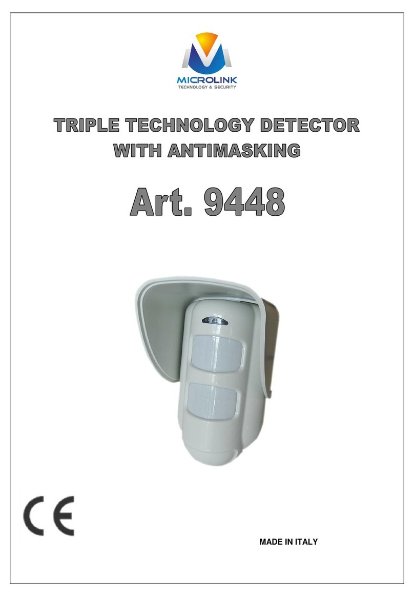
Microlink DM-448R User manual

1.5m
DM-448R series is a viewfinder passive infrared detector which adopts digital
micro-processor with energy-pile up-logical process, random dynamic time
split technology. The PIR parts adopt precision column lens to upgrade
receiving effect, higher sensitivity but lower false alarm. With the buit in
battery and the exclusive electricity save up model, it can be used for a long
time of as twice as the other brand detectors.
1. Introduction
PIR Lens
Picture 1:
appearance
Coding switch
Picture 2:
internal structure
Models
DM-448R
Transmit Distance:20-30M
Delay time : 15S-140Sadjustable (3greed
optianal)
In area (Typical)
/90
Alarm output radio transmit
Detection Range: 6M
Current Drain:About 10 A (common)
10mA(alarm)
PIR Section: Lens Data
18+2
Max. Coverage 6*1.5m
working frequency: 433MHz
Alarm indication:
Red LED lighting for 2 second
2.Specifications
Mount
hanging or ceiling mount: 1.8-2.8m
Environment:
Working Temperature: -10 C to 50 C(14 F to 122 F )
Storage Temperature :-20 C to 60 C (-4 F to 140 F)
Anti whitelight: 8000 LUX
Dimension:
H*W*D: 0*50*40m m
3.Installation
3.1 General Guidelines
Don't face cold
or heat directly
Don't face the sun-
shine directly
Do not install near
high-roltage cables
Don't face metal wall
3.2Anti-pests installation

4321
ON DIP
A. Press the tache
with a screw-drive
3.3Illustrated Installation Procedure
1 Disassemble unit
C. The PCB out
B. Remove the cover
1.8-2.8m beyond ground
A. Mark the drilling points
and drilling the wall
B. Insert two dowels and
attach the base to the wall
with two screws
C. Insert the bottom edge of
the large PCB under this
TAB & Press the top edge in
Surface
mount
3.5 The code way of detector and the control panel.
Code setting:
Install the battery insulation slice, the LED gives indication..
Please do code program to the alarm control panel at this time. After the
setting of the control panel tamper, press the dismantling switch, Then
the detector will generate deep to indicate successful operation.
Press this switch for code setting
3.6 How to change battery
When the detector batlery is weak, it will send out single
to the control panel, at the same time, the detector
flashes indicating at you need to change battery for the
detector. Draw the PCB board; follow the steps as below to change 4
new battery. ( as right picture ).
3.7 Setting of detection angle
When installing with a swivel bracket
(optional) .please refer to the right
diagram, to ensure the desired
(overage and feature).
At this angle, detection
angle is smallest, sensi-
tivity is highest. Loss pet
immunity function.
At this angle, detection angle is
largest, Lower section sensitivity
is low. Pet immunity up to 20Kg
At this angle, sensitivity
is in middle. Pet immun-
ity up to 10Kg
3.4 Instruction of code switches
1. NO .1switch is for event mode, when set “OFF”, the detector will
alarm when detecting any movement follow input the enacted
directed ;when set “ON”, when it detect movement following the
enacted directon, ut won’t alarm at once, until detect continuous
and keeping on movement, it will alarm (fit for room without passage)
2. NO .2 switch is LED switch, LED light when setting “ON”,during
working
3. NO .3 switch is for direction distinguish, when set “ON”, this funtion
available; when “OFF” ,any movement from any direction will trigger
alarm
4. NO .4 switch is for direction choose, left/right fit for different
surrounding
1.event mode switch
2.LED switch
3.Direction distinguish switch
4.Direction choose switch

1. Start the test at least 2 minutes after connecting power supply
3 .Testing in different direction to confirm the two boundaries of the
coverage, ensure the detector is appoint to the central desired area.
4. At 6m away from diliclor , raise slowly your arm and reach
into the detection zone, mark the lower limit of PIR detection. Do
the same step to confirm the upper limit.
5.the center of detection zone should not uphill incline. To obtain a
good detection range , please adjust the vertical detection range, en-
sure the detector is in a correct position.
2. Walking breadthwise at the remote and of the detection coverage
at the speed of 0.75m/s within 3m, then will trigger the detector and
the LED indications 2-3seconds.
6. After MW sensitivity or detection angle are adjusted, walking test
must be performed according to the above steps.
: after charge or the temper proof switch been pressed, the detector do self checking for 30 seconds then it get a period time
of 6 minutes for test. Within the test period, the human body moves according to the set direction until the system alarms, then
the indicating light lights and sends out the wireless alarm signal.
: after the testing period of 6minutes, it is the working period. Within this period, the human body moves according to the set
direction (such as enter into the room), if the LED ON is opened, then the indicating light lights and sends out the wireless
alarm signal. Then close the alarm, and test to see if any body is moving, until to the set alarm start up time, the system does
not detect the body movement, and confirmed to be away, then the detector can be started again.
When the human body moves against to the set direction (such as leave the room), the system does not alarm, Then close the
alarm, and test to see if any body is moving, until to the set alarm start up time, the system does not detect the body movement,
and confirmed to be away, then the detector can be started again.
After the reposition of the dismantle proof and magnetic switch on the detector, you will then get a period time6 minute for test. Within this time,
after the finish of automatic test, you can arrange the walking test. 6 minute later, the system enters into the working period. After one time alarm
within the working period, the system will check if there is any non-human activity for 140 seconds. Only after confirming that there is no human
activity for 140 seconds continuously, the detector will then start up the detecting model.
The testing period and working period
Special notice:
Testing period
Working period
3.10 Perform walking test to the detection area: install the cover and close the fasten part
(refer to the right diagram)
Important mention: Motion test shall be performed at least one time each
week in order to guarantee that each detector can keep excellent function.
Even the most sophisticated detcetors can sometimes be defeated or may fail to warn due to :DC power failure/improper connection, malicious mask-
ing of the lens,tampering with the optical system, decreased sensitivity in ambient temperatures near that of the human body and unexpected fail-
ure of a component part.The above list includes the most common reasons for failure recommended that the detector and the entire alarm system be ch-
ecked weekly, to ensure proper performance.An alarm system should not be regarded as a substitute for insurance. Home & property owners or renters sh-
ouldbe prudent enough to continue insuring their lives & property, even though they are protected by an alarm system.
WARNING! Changes or modifications to this unit not expressly approved by the party responsible for compliance could
void the user s authority to operate the equipment.
This device has been tested and found to comply with the limits for a Class B digitaldevice, pursuant harmful interference in residential installations .This equipment
generates,uses and can radiate radio frequency energy and ,if not installed and used in accordance with the ins-tructions ,may cause harmful in-terference to radio and t-
elevision reception. However, there is no guarantee that interference will not occur in aparticular installation .If this device does cause such interference , which can be ver-
fied by turning the device off and on ,the user is encouraged to eliminate the interference by one or more of the followingmeasures:
- Increase the distance between the device and the receiver.
- Connect the device to an outlet on a circuit different from the one that supplies power to the receiver.
- Consult the dealer or an expericnced radio/TV technician.
4.Special comments

OK
If LED switch is
off
To check if the
power connection
is proper
Check if the power accord
with 3VDC
power supply may
cut off
NG
NG
Connect it properly Check power system OK
Disconnect the terminal to c-
heck the power supply system
Indicator is off after power up
OK
Open the LED switch
NG
NG
Short circle or wrong earth conne-
ction in power supply, get rid of the
mistake
OK
NG
Power supply system has problem,
need to be repaired or contact the
power system supplier
To connect power supply
circle correctly
Thewirelengthofpower
supply is exceeded, or wire
diameter is too small. Please
change into fitted wire.
Wiring with unstable connection Change it
Check if the power is lower than
normal voltage DC3V
adjust the voltage of power supply
to ensure 3VDC
installation base unstable
OK
OK
NG
NG
If there is strong airflow like arcordition Eliminate false alarm sowrce
Choose stable base for
installation
False alarm
If there is pet weighting abase 20Kg Banish it
If the installation position less 1.8m Adjust the position according to the
manual
If there is high voltage electricfield Keep away from electrical power
If the detector face to metal wall Change installation position
Power supply problems Change it or repair it
5 Solution of usual problem
OK
LED indicates but no
signal outputs
Remove the cover to
check if the relay be on
Discomece the alarm output
to check if shot circuit
existime
If trouble with control
panel, contact suppliers
Please clear the trouble of short-circuit
NG
OK
NG
OK
Ask for help from supplier
No LED indication
and no alarm output
OK Check if the voetace
is 3VDC
Re power up the detector
to check if the LED indicates
NG
Change the walking voltage
into 3VDC
NG
OK
OK
OK Conduct walking test again
Conduct walking test in detection coverage, but no alarm output
Other Microlink Security Sensor manuals
Popular Security Sensor manuals by other brands

ESYLUX
ESYLUX MD-C360i/8 Series installation instructions

VIEWEG
VIEWEG DA35 instruction manual

Siemens
Siemens UP 255D21 5WG1 255-2DB21 Operating and mounting instructions

OI Analytical
OI Analytical 5380 Operator's manual

McGan
McGan MicroMed PD-8K Quick operation guide

Leviton
Leviton ODSMT-MD installation instructions