manuals.online logo
Brands
  1. Home
  2. •
  3. Brands
  4. •
  5. Micromark
  6. •
  7. Toy
  8. •
  9. Micromark Switch Tender 83201 User manual

Micromark Switch Tender 83201 User manual

Popular Toy manuals by other brands

FUTABA GY470 instruction manual

FUTABA

FUTABA GY470 instruction manual

LEGO 41116 manual

LEGO

LEGO 41116 manual

Fisher-Price ColorMe Flowerz Bouquet Maker P9692 instruction sheet

Fisher-Price

Fisher-Price ColorMe Flowerz Bouquet Maker P9692 instruction sheet

Little Tikes LITTLE HANDIWORKER 0920 Assembly instructions

Little Tikes

Little Tikes LITTLE HANDIWORKER 0920 Assembly instructions

Eduard EF-2000 Two-seater exterior Assembly instructions

Eduard

Eduard EF-2000 Two-seater exterior Assembly instructions

USA Trains EXTENDED VISION CABOOSE instructions

USA Trains

USA Trains EXTENDED VISION CABOOSE instructions

Modellbau Laffont Z1601 Assembly instructions

Modellbau Laffont

Modellbau Laffont Z1601 Assembly instructions

NOCH 12905 instruction manual

NOCH

NOCH 12905 instruction manual

Eduard Ki-61-Id quick start guide

Eduard

Eduard Ki-61-Id quick start guide

Viessmann Vollmer 45616 Mounting instruction

Viessmann

Viessmann Vollmer 45616 Mounting instruction

Vollmer 42004 Mounting instruction

Vollmer

Vollmer 42004 Mounting instruction

Phoenix Model CLASSIC-EP instruction manual

Phoenix Model

Phoenix Model CLASSIC-EP instruction manual

H-KING Sopwith Camel British WW1 Fighter instruction manual

H-KING

H-KING Sopwith Camel British WW1 Fighter instruction manual

MODSTER Predator 4x4 Crawler user manual

MODSTER

MODSTER Predator 4x4 Crawler user manual

DHK Hobby 8136 User instruction manual

DHK Hobby

DHK Hobby 8136 User instruction manual

THUNDER TIGER Raptor 50 V2 kit manual

THUNDER TIGER

THUNDER TIGER Raptor 50 V2 kit manual

Timberkits Skateboarder instructions

Timberkits

Timberkits Skateboarder instructions

Hangar 9 Funtana 125 Assembly manual

Hangar 9

Hangar 9 Funtana 125 Assembly manual

manuals.online logo
manuals.online logoBrands
  • About & Mission
  • Contact us
  • Privacy Policy
  • Terms and Conditions

Copyright 2025 Manuals.Online. All Rights Reserved.

If your track switch has not yet been installed, follow these instructions:
As shown in Figure 2, create a slot through the roadbed and/or track support board under the hole in
the throwbar of the track switch. Do this by drilling two 1/8" diameter holes about 3/16" apart (for HO
gauge track), then cut and file out the space between them. Be careful to leave the hole smooth and
splinter-free. Note: For scales larger than HO, make the slot correspondingly longer.
Figure 3 shows the track switch installed with the hole in the throwbar positioned above the slot. Be
sure the slot is wide enough to clear the throwbar hole when the track switch is completely thrown in
either direction.
On the underside of the track support board, drill a 1/8" diameter x 1/2" deep hole at a distance 1-1/2"
to 1-3/4" from the slot. Remove the mounting bracket clamping screw and install the mounting bracket
with the mounting screw provided in the kit as shown in Figure 4.
Install the brass wire through the hole in the motor shaft as shown in Figure 5. Place the end of the
wire through the hole, then tightly wrap it around the motor shaft as shown. It will stay in an upright
position with just a small amount of wobble (which is just what we would like to have) and act as the
throw rod for the track switch.
Spread the gap in the mounting bracket, then snap the motor into place in the bracket as shown in
Figure 6. At the same time, guide the throw rod wire up through the hole in the track switch throw bar
as shown in Figure 7. Reinstall the clamping screw and adjust the motor position so that the throw rod
wire clears all edges of the slot. Trim off excess throw rod wire as shown in Figure 8 (be careful to
leave a little extra so it doesn't slip out of the hole when the switch is thrown).
Skip the next part of the instructions and proceed to: Electrical Hook-Up and Final Adjustment
The Switch Tender is a stall-motor switch machine. That means that the motor runs until it throws
the track switch; then, it simply stalls, holding the points tightly against the stock rails. A resistor
(provided), installed in either one of the motor lead wires, prevents the motor from overheating in
the stalled position, even though the electrical power to the motor remains on. To throw the points
in the other direction, simply reverse the polarity of the motor connections using an electrical toggle
switch (not included...we recommend the Micro-Mark #83257 3PDT Toggle Switch, which will also
route power of the proper polarity to the frog of the track switch). Installation of the Switch Tender
requires ordinary hand tools, such as a flat tip screwdriver, needle-nose plier, small file, wire nipper
and wire stripper; an electric drill with 1/8" and 1/16" diameter bits will make things easy. After you
gain a little experience with installation, you should be able to install a Switch Tender in about 5
minutes (It takes longer to read the detailed instructions below than to install the Switch Tender).
Note: Dimensions given in the instructions are intended for HO gauge switches.
Adjust them accordingly for your track gauge.
The Switch Tender can be mounted either before (quite simple) or after (a little more work)
installation of your track switch. Instructions for both situations follow...
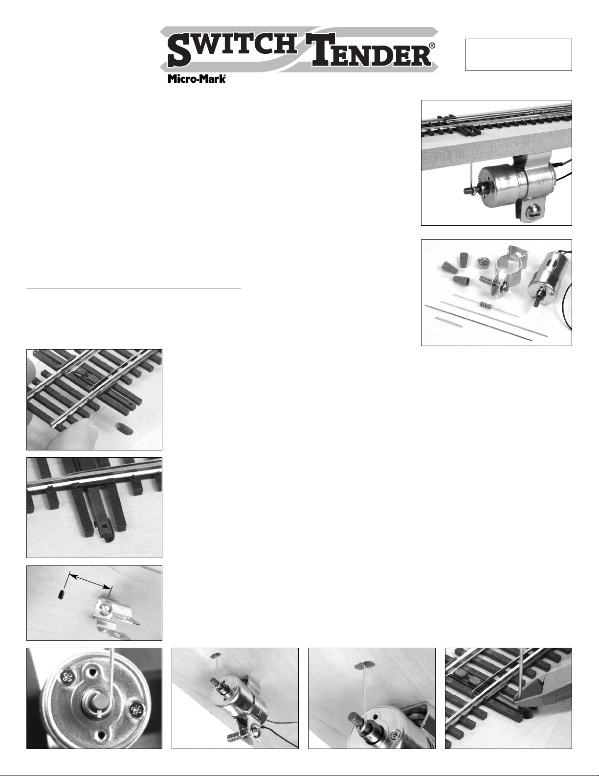
Figure 1
Figure 2
Figure 3
Figure 4
Figure 5
Figure 6 Figure 7 Figure 8
1-5/8”
MM040405
Figure 1 shows the contents of your Switch Tender kit:
1 premium quality motor with integral slow-motion gearhead
1 mounting bracket with clamping screw
1 mounting screw
1 resistor (150 ohm, 1 watt)
1 brass tube
1 steel wire
1 brass wire
3 wire nuts
This product contains lead, a chemical
known to the State of California to
cause cancer and birth defects or
other reproductive harm.
340 SNYDER AVENUE, BERKELEY HEIGHTS, NJ 07922
If your track switch has already been installed, follow these instructions:
Bend a square hook in the end of the steel wire as shown in Figure 9.
Slide the long end of the wire through the brass tube.
Drill a 1/16" diameter hole through the track roadbed and base board
adjacent to the throw bar hole as shown in Figure 10. Space the drilled
hole from the throw bar so that the tip of the hook will engage the hole
in the throw bar. Install the brass tube in the hole and engage the hook
in the throw bar hole. If the hook drags on the roadbed, adjust the
height of the brass tube and/or trim the wire before going any further.
On the lower end of the brass tube, make a right angle bend in the
steel wire as shown in Figure 11 in the direction of the motor. This
steel wire will now act as the throw rod crank.
Drill a 1/8" diameter x 1/2" deep hole at a distance 2" from the brass
tube in line with the bent steel wire. Remove the mounting bracket
clamping screw. Install the mounting bracket with the screw provided
as shown in Figure 12.
Install the brass wire through the hole in the motor shaft as shown in
Figure 13. Place the end of the wire through the hole, then wrap it
tightly around the motor shaft as shown. It will stay in an upright
position with a small amount of wobble.
Make an additional bend in the brass wire so it will engage the steel
wire throw rod crank as shown in Figures 14 and 15. Install the motor
by snapping it into the bracket while engaging the throw bar linkage,
and reinstall the clamping screw to hold everything in position. Trim the
ends of the throw rod wires as necessary for clear travel.
Electrical Hook-Up and Final Adjustment
Connect a resistor to either one of the motor leads using a wire nut as
shown in Figure 16. Be sure the motor lead is stripped sufficiently long
to form a tightly twisted pair with the resistor lead.
Use the remaining two wire nuts to temporarily connect the two wire
ends (one from the resistor and one from the motor) to a 12 volt DC
supply and adjust the motor position and wire linkage as necessary to
obtain a good throw of the track switch points. Tip: If the steel wire
throw rod crank (if used) slips out of the brass throw rod, move the
motor closer to the crank. Reverse the motor leads, and check
operation again. Then connect your final wiring.
Figure 13
Figure 9
Figure 10 Figure 14
Figure 15
Figure 16
Figure 11
Figure 12
3/8”
340 Snyder Avenue
Berkeley Heights, NJ 07922
Tech Support: 908-464-1094 www.micromark.com MMT[email protected]
Copyright 2005 by
2”
SWITCH TENDER
WIRING DIAGRAM
If your turnouts already
route power to the frog
through the points, do not
use the extra contacts on
the toggle switch to power
the frog. If you have a very
many Switch Tenders, use
a power supply of sufficient
power to handle the load:
supply 1 amp for each
16 Switch Tenders.