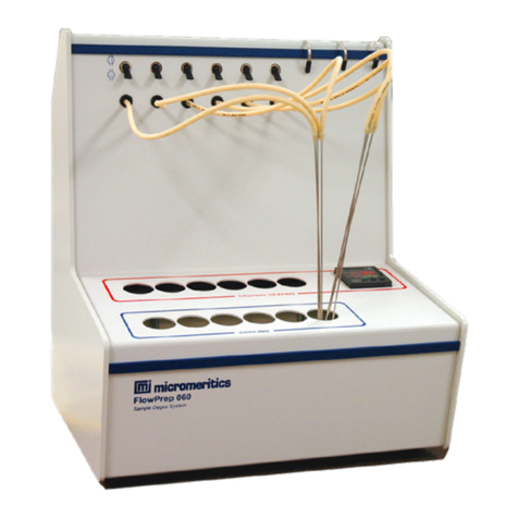
Micromeritics FlowSorb III 2305 User manual

FlowSorb III 2305/2310
for
determining
Single Point and Multipoint Surface
Area
Operator’s Manual
231-42801-01
March 2012

© Micromeritics Instrument Corporation, 2001-2012. All rights reserved. Printed in U.S.A.

TABLE OF CONTENTS
1. GENERAL INFORMATION
Introduction . . . . . . . . . . . . . . . . . . . . . . . . . . . . . . . . . . . . .1-1
Conventions . . . . . . . . . . . . . . . . . . . . . . . . . . . . . . . . . . . . .1-2
Intended Use and Precautions . . . . . . . . . . . . . . . . . . . . . . . . . . . 1-2
Intended Use . . . . . . . . . . . . . . . . . . . . . . . . . . . . . . . . . 1-2
Precautions . . . . . . . . . . . . . . . . . . . . . . . . . . . . . . . . . .1-3
General . . . . . . . . . . . . . . . . . . . . . . . . . . . . . . . . . 1-3
Dewar . . . . . . . . . . . . . . . . . . . . . . . . . . . . . . . . . .1-4
Description . . . . . . . . . . . . . . . . . . . . . . . . . . . . . . . . . . . . .1-5
FlowSorb III 2310 . . . . . . . . . . . . . . . . . . . . . . . . . . . . . . 1-5
FlowSorb III 2305 . . . . . . . . . . . . . . . . . . . . . . . . . . . . . . 1-6
Principle of Operation . . . . . . . . . . . . . . . . . . . . . . . . . . . . . . . 1-7
Basic Construction . . . . . . . . . . . . . . . . . . . . . . . . . . . . . . . . . 1-8
Components and Controls . . . . . . . . . . . . . . . . . . . . . . . . . . . . . 1-10
Sample Tube . . . . . . . . . . . . . . . . . . . . . . . . . . . . . . . . .1-10
Heating Mantle . . . . . . . . . . . . . . . . . . . . . . . . . . . . . . . . 1-11
Dewar Support . . . . . . . . . . . . . . . . . . . . . . . . . . . . . . . . 1-11
Instrument Display . . . . . . . . . . . . . . . . . . . . . . . . . . . . . . 1-12
Threshold . . . . . . . . . . . . . . . . . . . . . . . . . . . . . . . . . . .1-13
Cold Trap . . . . . . . . . . . . . . . . . . . . . . . . . . . . . . . . . . .1-13
Gas Flow Paths . . . . . . . . . . . . . . . . . . . . . . . . . . . . . . . .1-14
Septum . . . . . . . . . . . . . . . . . . . . . . . . . . . . . . . . . . .1-14
Other . . . . . . . . . . . . . . . . . . . . . . . . . . . . . . . . . . . . .1-14
Specifications . . . . . . . . . . . . . . . . . . . . . . . . . . . . . . . . . . . .1-15
2. INSTALLATION
Unpacking and Inspecting the Equipment . . . . . . . . . . . . . . . . . . . . 2-1
Equipment Damage or Loss During Shipment . . . . . . . . . . . . . . . 2-1
Equipment Return . . . . . . . . . . . . . . . . . . . . . . . . . . . . . . 2-1
Selecting the Location . . . . . . . . . . . . . . . . . . . . . . . . . . . . . . . 2-2
Selecting the Input Power . . . . . . . . . . . . . . . . . . . . . . . . . . . . . 2-3
Connecting the Gas Supply . . . . . . . . . . . . . . . . . . . . . . . . . . . . 2-7
Installing and Removing a Sample Tube . . . . . . . . . . . . . . . . . . . . . 2-9
Installing a Heating Mantle . . . . . . . . . . . . . . . . . . . . . . . . . . . . 2-10
Using a Cold Bath . . . . . . . . . . . . . . . . . . . . . . . . . . . . . . . . . 2-11
Aug 00 i

Table of Contents FlowSorb III
ii
Aug 00
3. OPERATION
Preparing the FlowSorb for Operation . . . . . . . . . . . . . . . . . . . . . . .3-1
Degassing the Sample . . . . . . . . . . . . . . . . . . . . . . . . . . . . . . .3-3
Degassing Considerations . . . . . . . . . . . . . . . . . . . . . . . . . .3-4
Sample Considerations . . . . . . . . . . . . . . . . . . . . . . . . . . . .3-4
Performing a Single-Point Surface Area Measurement . . . . . . . . . . . . . . 3-5
Calibration . . . . . . . . . . . . . . . . . . . . . . . . . . . . . . . . . . .3-5
Analysis . . . . . . . . . . . . . . . . . . . . . . . . . . . . . . . . . . . .3-7
FlowSorb III 2305 . . . . . . . . . . . . . . . . . . . . . . . . . . .3-8
FlowSorb III 2310 . . . . . . . . . . . . . . . . . . . . . . . . . . .3-9
Performing a Multipoint Surface Area Measurement . . . . . . . . . . . . . . . 3-11
Calibration . . . . . . . . . . . . . . . . . . . . . . . . . . . . . . . . . . .3-11
Analysis . . . . . . . . . . . . . . . . . . . . . . . . . . . . . . . . . . . .3-14
Calculating the Result . . . . . . . . . . . . . . . . . . . . . . . . .3-15
Preparing the FlowSorb for Idle Periods . . . . . . . . . . . . . . . . . . . . . 3-17
4. TROUBLESHOOTING AND MAINTENANCE
Troubleshooting . . . . . . . . . . . . . . . . . . . . . . . . . . . . . . . . . . .4-1
Detector Drift . . . . . . . . . . . . . . . . . . . . . . . . . . . . . . . . .4-1
Low Results On X10 Range . . . . . . . . . . . . . . . . . . . . . . . . .4-2
Erratically High Results . . . . . . . . . . . . . . . . . . . . . . . . . . .4-2
Non-Reproducible Calibrations . . . . . . . . . . . . . . . . . . . . . . .4-3
Surface Area Display Not Clearing to Zero . . . . . . . . . . . . . . . . 4-4
Degas Temperature Fails to Function Properly . . . . . . . . . . . . . . . 4-4
Display and Indicators Fail to Illuminate . . . . . . . . . . . . . . . . . . 4-5
Hard-to-Release Sample Holder . . . . . . . . . . . . . . . . . . . . . . .4-5
Substantial Difference Between Adsorption and Desorption Result . . . . 4-5
Lodged Flowmeter Float . . . . . . . . . . . . . . . . . . . . . . . . . . .4-5
Replacing the Septum . . . . . . . . . . . . . . . . . . . . . . . . . . . . . . .4-6
5. ORDERING INFORMATION
APPENDICES
Appendix A: Theory
Appendix B: Other Gases and Compositions
Appendix C: Specialty Gas Source
Appendix D: Sample Tubes

CHAPTER 1
GENERAL INFORMATION
•
Introduction
•
Conventions
•
Intended Use and Precautions
•
Description
•
Principle of Operation
•
Basic Construction
•
Components and Controls
•
Specifications


FlowSorb III Introduction
Mar 2012
1-1
GENERALINFORMATION
Introduction
This manual describes the installation and operation of the FlowSorb III; its con-
tents are organized as follows:
Chapter 1 General Information. Provides a general description of the
FlowSorb III, its features, safety precautions, and specifications.
Chapter 2 Installation. Describes how to unpack, inspect, and install the
FlowSorb III.
Chapter 3 Operation. Provides instructions on operating the FlowSorb III.
Chapter 4 Troubleshooting. Provides troubleshooting information.
Chapter 5 Ordering Information. Provides ordering information for accesso-
ries and components available for the FlowSorb III.
Appendix A Theory. Provides a discussion on the theory of the FlowSorb III.
Appendix B Other Gases and Compositions. Provides information on
recommended gas compositions.
Appendix C Specialty Gas Source. Contains the addresses of recommended
gas sources.
Appendix D Sample Tubes. Provides illustrations and a discussion of the sam-
ple tubes to be used with the FlowSorb III.
Index Provides quick access to a subject matter.

Intended Use and Precautions FlowSorb III
1-2
Mar 2012
Conventions
This manual uses the symbols shown below to identify notes of importance, cau-
tions, and warnings.
Notes contain pertinent information with reference to the subject matter.
Cautions contain information to help you prevent actions which could
damage the instrument.
Warnings contain information to help you prevent actions which could cause
personal injury.
Intended Use and Precautions
Intended Use
The FlowSorb III is designed to measure rapidly the surface area on the molecu-
lar level of stable, granulated, and powdered materials. Surface area measurement
can be accomplished either by a simplified, single-point procedure or by the more
conventional multipoint BET technique (see Appendix A). The FlowSorb III 2310
is automatic and requires no operator intervention other than preparing, installing,
and removing the sample. The FlowSorb III 2305 is manually operated.
Both models measure with diminishing effectiveness the physical properties of ma-
terials which have appreciable vapor pressures, i.e., materials which slowly evapo-
rate or sublimate. Deposition of recondensed vapors within the instrument will
eventually lead to unsatisfactory performance.

Mar 2012
1-3
FlowSorb III Intended Use and Precautions
Precautions
Read all of the precautions contained in this section and observe them at all
times when operating the FlowSorb III.
General
•
Certain solids when heated give off corrosive vapors. Such vapors can
damage instrument components. The degassing feature of the FlowSorb is
intended primarily for the removal of adsorbed water vapor and non-con-
densible gases acquired through normal atmospheric exposure. Cleanup of
unusually contaminated samples should be accomplished prior to installa-
tion on the instrument. The DeSorb 2300A is available for this use as well
as for routinely speeding sample throughput.
•
The gas composition detectors are sensitive to the presence of oxygen
when turned on. The FlowSorb must be purged of oxygen by flowing an
inert gas, or mixture of inert gases, through it for at least five minutes be-
fore power is applied. This precaution applies especially when the instru-
ment is initially installed and after it has been stored for a period of time.
Should the inert gas supply be inadvertently depleted or somehow discon-
nected while the FlowSorb is in operation, the power should immediately
be turned off and the system purged of oxygen before reapplying power.
•
Unplug the power cord before removing the rear panel to gain access to in-
ternal components. Connections carrying potentials as great as 240 V can
be encountered.
•
While liquid nitrogen is the most commonly employed coolant, it is possi-
ble to use liquid argon and a variety of slush baths involving organic sol-
vents. These latter require special precautions. Be sure that no hot or
burning combustible material comes near either liquid argon or flammable
solvents. A lighted cigarette poses a particular hazard in both cases.
•
Do not invert a sample holder once powdered sample is placed in a sam-
ple tube and the tube is attached to the holder. Particles can lodge in the
quick-disconnect seals causing them subsequently to malfunction. Reten-
tion of particles in the mechanism also produces a sample weight error.
Should this happen, thoroughly clean the holder and reweigh the sample
before proceeding.
•
Do not detach from the FlowSorb a sample holder that contains a sample
at, or near, liquid nitrogen temperature and having gas still adsorbed on
the sample. The sample holder seals automatically upon removal and,
upon warming, previously adsorbed gas may be released, raising the pres-
sure in the holder to a dangerous level.

1-4
Mar 2012
Intended Use and Precautions FlowSorb III
Dewar
Always handle dewars with care. Any product incorporating a vacuum is a
potential safety hazard and should be treated with caution. Always observe
the precautions listed below.
We recommend the following be observed when handling dewars containing lique-
fied gases:
•
Protect yourself by wearing 1) goggles (or a face shield), 2) an insulated
or rubber apron, and 3) insulated gloves.
•
When pouring liquefied gases from one container to another: 1) cool the
receiving container gradually to minimize thermal shock, 2) pour the lique-
fied gas slowly to prevent splashing, and 3) vent the receiving container to
the atmosphere.
•
Use a plastic stirring rod when stirring substances in a dewar containing
liquefied gases (or other materials of extremely low temperature). Do not
use a glass or metal stirring rod unless it is coated with some type of pro-
tective coating.
•
Do not remove the mesh covering from the Dewar flask. This covering is
in place to minimize the risk of flying particles if the Dewar is acciden-
tally knocked over or dropped and broken.
•
Do not handle heavy objects above the dewar. If unavoidable, place a pro-
tective cover over the dewar’s opening. If an object of sufficient weight is
accidentally dropped into the dewar, shattering may occur.

Mar 2012
1-5
FlowSorb III Description
Description
The FlowSorb III is available in two models: the FlowSorb III 2305 and the
FlowSorb III 2310. The FlowSorb III provides single-point and multipoint analy-
ses, as well as the capability of reporting desorption isotherms. Adsorption iso-
therms can also be reported if using the FlowSorb 2305. Samples from 0.01 m2/g
to greater than 1,000 m2/g are easily accommodated with a reproducibility of bet-
ter than 0.5%. Both models are shown in the following sections with the differing
features called out. All other features are the same on both models.
FlowSorb III 2310
Start and Reset
Buttons
A fan is included for
warming the sample to
room temperature (con-
cealed in this illustra-
tion by the Dewar)
Track for Automatic
Elevator
The FlowSorb III 2310 allows you to measure surface area from desorption meas-
urements. This model is automatic and requires no operator intervention after the
Dewar is placed on the Dewar tray and the Start push button is depressed. The
Dewar rises automatically about the sample and analysis begins. After adsorption
is completed, the Dewar lowers and a fan turns on to warm the sample to room
temperature, allowing desorption to proceed to completion.

1-6
Mar 2012
Description FlowSorb III
FlowSorb III 2305
The FlowSorb III 2305 is
manually operated and does
not include Start and Reset
buttons, a warming fan, or an
elevator.
Dewar Platform
Release Button
The FlowSorb III 2305 reports adsorption and desorption measurements. This
model requires the operator to place the Dewar on the Dewar tray and move it
up about the sample for analysis to begin. After adsorption is complete, the opera-
tor is required to remove the Dewar and warm the sample to room temperature,
after which the desorption measurement is reported.

Mar 2012
1-7
FlowSorb III Principle of Operation
Principle of Operation
The surface area of granulated and powdered solids or porous materials is meas-
ured with the FlowSorb III by determining the quantity of a gas that adsorbs as a
single layer of molecules, a so-called monomolecular layer, on a sample. This ad-
sorption is done at or near the boiling point of the adsorbate gas. Under specific
conditions, the area covered by each gas molecule is known within relatively nar-
row limits. The area of the sample is thus calculable directly from the number of
adsorbed molecules, which is derived from the gas quantity at the prescribed con-
ditions, and the area occupied by each.
For a nitrogen and helium mixture of 30 volume percent nitrogen, conditions most
favorable for the formation of a monolayer of adsorbed nitrogen are established
at atmospheric pressure and the temperature of liquid nitrogen. Parameters defining
the conditions at which the monolayer forms are incorporated in the multipoint
analysis result by the data treatment. Atmospheric pressure and ice water
temperature may establish appropriate conditions for a n-butane and helium mix-
ture. Other gases at other conditions are also usable.
In general, a surface area result obtained by the multipoint method using nitrogen
as the adsorbate is somewhat more reliable than a single point one, and nitrogen
gas is preferable over other gases. Unless special circumstances dictate, nitrogen
is recommended.
Refer to Appendix A for additional information on FlowSorb theory.

1-8
Mar 2012
Basic Construction FlowSorb III
Basic Construction
Functionally, the FlowSorbs III 2305 and 2310 are identical. The FlowSorb III
2305 requires the operator to submerge the sample in cryogenic liquid to induce
adsorption, then to remove the cryogen and warm the sample for desorption. This
operation is automatic when using the Flowsorb III 2310.
Long
Path
Filter Septum
Test
Sample
Flow
Adjustment
Valve
Back
Diffusion
Restrictor
Flowmeter
Short
Path
Differential
Flow
Controller
On/Off
Valve
Gas Out
Degas
Matched Thermal Conductivity Cells
Cold Trap
Gas In
Figure 1-1. Schematic Diagram
Mechanically, the FlowSorb III consists of: (1) components to turn on and off gas
flow (the ON/Off Valve), regulate the flow (the Flow Adjustment Valve), direct the
flow (the Path Switch), and indicate the flow rate (the Flowmeter); (2) attachment
points at which the gas passes through a freeze-out trap to remove traces of
moisture that may be present in the gas (Cold Trap), points at which the sample is
exposed to heated gas to free it of extraneous gases and vapors (Degas), and
points at which to perform the test (Test); (3) a septum by means of which a
known amount of gas is introduced for calibration purposes; (4) a filter to prevent
powder carryover into critical parts; (5) matched thermal conductivity cells
operating at a fixed temperature of 42 ±1 oC (107.6 ±1.8 oF) for gas concentration
detection; (6) a valve arrangement by which gas entry into one of the cells can be
delayed more than normally; (7) an automatic elevator on the FlowSorb III 2310
and a Dewar flask support platform on the FlowSorb 2305; and (8) an air blower
in the FlowSorb III 2310 to warm the sample automatically to room temperature.

Mar 2012
1-9
FlowSorb III Basic Construction
Electrical and electronic components include: (1) an on/off power switch, univer-
sal power entrance, and fuse block; (2) a power supply; (3) a thermal conductiv-
ity sensor and amplifier circuit; (4) a conductivity cell output linearization circuit;
(5) a heating mantle temperature setting and feedback control system; (6) an indi-
cator with appropriate selection switches for displaying the measured surface area
by the single-point technique and the adsorbed gas volume for multipoint testing,
the sample degassing temperature, and the thermally detected signal; (7) adjust-
ments for initial calibration; and (8) on the FlowSorb III 2310 only, start and re-
set controls.

1-10
Mar 2012
Components and Controls FlowSorb III
Components and Controls
This section provides a brief description of the use, manipulation, and function of
major components and controls of the FlowSorb.
Sample Tube
Glass tubes in a variety of generally U-shaped configurations are used to hold the
sample. Pertinent details about these tubes are given in Appendix D. The two
stems of a tube are inserted into tightenable connectors on the sample tube
holder. The tightenable connectors seal by means of compressed O-rings. This as-
sembly is then installed in the Degas or Test position on the front panel. Chapter
2 provides instructions on how to install a sample tube.
Sample Tube Holder
Sample Tube
Figure 1-2. Sample Tube and Holder

Mar 2012
1-11
FlowSorb III Components and Controls
Heating Mantle
A heating mantle is installed on a sample tube only when in the Degas position.
Its purpose is to maintain the specified temperature (specified using the Temp
Set dials). The mantle is slid upward about the sample tube and held in place
with a flared U-clamp. Refer to Chapter 2 for instructions on properly installing a
heating mantle.
U-Clamp
Figure 1-3. Mantle Installation
Dewar Support
A Dewar of cooling liquid around the sample tube is required to initiate gas
adsorption.
•
FlowSorb III 2310: The Dewar tray is directly below the sample analysis
port near the base of the instrument platform. The Dewar is placed on the
tray. The tray rises automatically when the analysis is started, inserting the
sample tube into the cooling liquid within the Dewar. The tray lowers for
removal of the Dewar automatically after adsorption data are collected. No
operator involvement is required.
•
FlowSorb III 2305: The Dewar is supported by a hinged platform. The
platform hangs down when not in use. The Dewar is manually brought up
around the sample and the platform swung upward where it locks into
place. The Dewar is removed by holding the Dewar with one hand and
pressing the Release button to the right of the platform. This causes the
platform to drop out of the way, allowing you to remove the Dewar.
When the platform is raised, the instrument automatically collects adsorption data.
When it is down, desorption (or evaporation) data are collected. There is no
need, nor other means provided, to select between adsorption and desorption data.

1-12
Mar 2012
Components and Controls FlowSorb III
Instrument Display
A single, multifunction display meter in the upper center of the front panel serves
to display the following (selected by pushbuttons below the display):
•
surface area for single-point analyses
•
adsorbed gas volume for multipoint analyses
•
degas temperature during degassing
•
detector signal
Clear SA Display
pushbutton
Not included on the
FlowSorb III 2305
The signal chosen for display can be shifted at any time in any sequence without
detriment to the other signals. Surface area information and gas volume data,
whether displayed or not, are retained after a test is completed until the Clear SA
Display button to the left of the meter is depressed.
Surface area and adsorbed gas volume are displayed in terms of the quantity of
sample contained in the sample tube. This means the displayed number must be
divided by the sample weight to convert it to specific surface area (m2/g) or spe-
cific volume (cm3/g).
The detector signal is calibrated to indicate the instantaneous difference in percent
nitrogen between the reference mixture and that currently in the detector. The x1
scale indicates differences up to 100% while the x10 scale indicates a maximum
difference of 10%.
The degas temperature is displayed as degrees Celsius.
The FlowSorb III 2310 has two additional pushbuttons below the display meter.
The Start push button is depressed after the degassed sample has been trans-
ferred to the Test position for analysis. The Reset button is used to abort an
analysis; the analysis stops and the instrument returns to initial conditions.

Mar 2012
1-13
FlowSorb III Components and Controls
Threshold
Threshold indicator
The Threshold indicator lamp to the left of the display meter flashes when the
accumulated adsorption or desorption signal is greater than the threshold level.
The more rapid the flashing, the greater the magnitude of the signal. This lamp is
designed to begin indicating accumulation of signals as follows:
•
x1 scale: between +0.06% and +0.07% nitrogen. It stops indicating when
the signal falls between +0.03% and +0.04% nitrogen.
•
x10 scale: between +0.010% and +0.011% nitrogen. It stops indicating
when the signal falls between +0.008% and +0.009% nitrogen.
Cold Trap
A Cold Trap is provided for the removal of vaporous impurities in the analysis
gas stream, especially water vapor. These type impurities tend to be present in
small amounts in commercial gases and are detrimental to surface area evalu-
ation.
A Dewar with a segmented stopper and a longer-than-normal U-tube are provided
for this use. The U-tube is attached by means of the same tightenable connectors
as on sample tubes. The stopper is designed to encase snugly the U-tube stems.
The stopper is segmented so that the Dewar can be initially filled and refilled in
place by removing only the front half of the two-part stopper.
The Dewar is normally filled with liquid nitrogen when making surface area tests
although other coolant baths can be used with special gases.

Specifications FlowSorb III
1-14
Mar 2012
Two gas flow paths, labeled Short and Long, are provided downstream of the
sample Test position. The purpose of both is, upon removal of the liquid nitro-
gen, to delay the arrival at the detector of the nitrogen-rich gas (created by sam-
ple desorption) long enough for the flow rate to return to normal. The Short path
is usually sufficient for surface area testing. Greater surface area materials may
give up too much gas over too long a time for a short path and, therefore, the
Long path should be used.
Septum
FlowSorb calibration is accomplished by means of a septum through which
known volumes of gas are injected with a precision syringe. Any septum will
leak after some number of penetrations. The supplied syringe needles have side-
entry ports which greatly extend this life. Nevertheless, this septum will require
replacement periodically. Refer to Chapter 4 for instructions on replacing the
septum.
The knurled nut retaining the septum should be finger-tightened. Insufficient
or excessive tightening may cause septum leakage.
Other
The controls not covered here are fully described in connection with the opera-
tion or calibration procedures.
This manual suits for next models
1
Table of contents
Other Micromeritics Test Equipment manuals