Micron Radio Control MR001d User manual

Manual Bind
Uplands House, Castle Howard Road, Malton YO17 6NJ
www.micronradiocontrol.co.uk
+44 (0)1653 696008
Micron MR001d Quick Start Guide
This guide is designed to get you started with MR001d as quickly as possible. More information can be
found in the user manual - http://micronrc.uk/mr001d-info.
MR001d is a 2.4GHz DSM2/DSMX 11 output receiver designed for model railway use. It is suitable for
live steam and large battery electric locos. It can be used to drive servos, speed controllers and LEDs.
If purchased with a transmitter, MR001d will be bound to the transmitter and is ready for use;
otherwise, it requires binding to your transmitter. Once bound, the transmitter should be switched on
before the MR001d. If the transmitter is not switched on, MR001d will automatically enter bind mode 5
seconds after switch on; it also be manually bound using a jumper plug on the P5/P7 signal pins.
Usage
Do not bend the receiver circuit board or use with the protective sleeve removed.
Ensure unused pins of P1..P7 cannot contact any metal.
Connect to a battery or ESC output that can provide 3.5V to 8.5V under load. Some servos can
draw a heavy current when starting to move and the voltage of a 'tired' 4 cell NiMH battery may
dip below 3.5V causing MR001d to reset. If this happens, a 5 cell NiMH battery will give better
results. A resettable fuse in the battery positive lead is recommended to protect the battery in the
event of a wiring or component fault. If you need to power from a single LiPo cell (e.g. because of
space reasons), a 5V or 6V booster should be used.
If MR001d has not been supplied configured for your use, set the throttle mode, Selecta and
Cruise control features as required (see 'Power-On-Changes').
If required, bind to your transmitter (see 'Binding').
Connect your servo(s) or speed controller to the appropriate pins (see 'Connection Diagrams') and
adjust the servo direction and/or travel as required (see 'Servo Adjustment').
Fix MR001d in place and route the aerial(s) so that it can 'see' the transmitter for best range -
e.g. by routing through a hole in the vehicle body. If the receiver is totally enclosed within a metal
body, the extended aerial version should be used, the last 30mm is the actual aerial. The aerial
should not be cut short or made longer as this will affect operation. It is important to perform a
range check after installation to ensure you have full control of your loco at all positions around
the layout. Double sided foam-cored sticky tape is ideal for mounting the receiver.
Binding
To bind:
1. with transmitter off, switch MR001d on
2. wait for the LED to flash fast
3. switch your transmitter on in bind mode
4. the LED will stop the rapid flash, flash slowly for a while and then
light continuously
5. MR001d is now bound to your transmitter
If the receiver LED does not come on solid (no flash) within 10-15 seconds, the bind process has failed.
This can happen for several reasons and does not normally indicate a fault. If you get a bind fail, try
again after moving the Tx and Rx slightly further apart or changing the relative orientation of the
aerials. Binding is most reliable when no other 2.4GHz transmitters are turned on.
Connections
MR001d has 7 sets of output pins which can be used for servos, speed controllers or LEDs for lighting.
The pin sets, numbered from the top of the diagram below, are 0.1" pitch to take standard R/C plugs.
An additional 4 outputs are available via an optional JST-SH socket at the aerial end of the receiver.
Although the connector has 3.3V and 0V pins, it cannot be used for powering a servo as the 3.3V pin is
Micron R/C, www.micronradiocontrol.co.uk, +44 (0)1653 696008 Micron MR001d Quick Start Guide : 1 of 4

ESC Connection
Servo Connection
supplied from the on-board regulator which has insufficient current capacity for a servo.
Connections
A connector with 100mm leads is supplied with the JST-SH socket option is selected at purchase.
Throttle Modes
The transmitter's throttle control is output on P1 (default configuration, may be changed by
programming) to drive a regulator servo or an external speed controller. The throttle mode is used
mainly to control how the directional lights operate and to close the throttle if the emergency stop
feature is enabled or cruise control is disabled. Also, there will be no output from P1 until MR001d has
received a valid stop throttle signal.
The 3 throttle modes are:
centre-off
Forward and reverse on one transmitter control with stop in the centre. Best used with an external
forward/reverse speed controller connected to P1 as shown in the 'ESC Connection' diagram.
MR001d is powered from the speed controller's 5V output. This is the default mode and MR001d
will be supplied centre-off unless otherwise requested.
low-off
Separate transmitter controls for speed and direction which are output on P1 and P3 (R/C
channels 1 and 3). This mode is suitable for most live steam locos.
low-to-centre
Separate speed and direction transmitter controls are combined into one forward/reverse output
on P1. This mode is intended for battery electric locos where the user prefers separate controls or
who wants to use a transmitter for both live steam and battery locos.
The throttle control min and max positions will require calbration the first time MR001d is
switched on in this mode. After initialisation, the LED will display a repeated pattern of 1 long
flash followed by 1 short flash. Move the transmitter throttle control to its minimum CCW position
(stop) then move it to the maximum CW position (full speed) and finally back to stop. The LED
will then light continously.
Power-on-Changes
Some MR001d configuration changes may be done using one or more jumpers placed on the P1..P7
signal pins before the receiver is switched on. The LED will display a flash pattern corresponding to the
selected change. The table below summarises the available changes and the associated flash patterns.
The changes all cycle though the flash counts while the jumper is installed. Each flash count is
repeated once (i.e. shown twice) and then increments to the next, cycling back to 1 when the
maximum is reached. When the desired flash count has been shown, removing the large jumper
acknowledges the selection by showing a rapid flash. There will be a short delay between removing the
jumper and the rapid flash due to the time taken to write the changes to permanent memory. The
Micron R/C, www.micronradiocontrol.co.uk, +44 (0)1653 696008 Micron MR001d Quick Start Guide : 2 of 4

receiver should be powered off when the rapid flash starts. If you switch off before removing the
jumper connection, the configuration is not changed. If you switch off after removing the jumper and
before the rapid LED flash, the receiver data is likely to be corrupted and you should perform a reset.
It is recommended to do a backup after making any other changes (including any programming via a
transmitter - see http://micronrc.co.uk/mr001d-progtable).
Change Large
Jumper
Small
Jumper
LED indication
* = default setting
Reset &
Backup
P1/P3 - n-flash where 'n' is:
1: do nothing
2: reset
3: backup
4: disable/enable ch2/ch4 programming
Configuration
Select
P1/P3 P4/P5 n-flash where 'n' is the configuration number
Throttle Arm
Mode
P1/P3 P5/P6 This controls the way that the throttle output (normally P1)
behaves after switch on:
1-flash = disabled (output follows Tx throttle immediately)
2-flash = enabled (output disabled until Tx throttle at stop) *
LED2 P2/P4 - 1-flash - disabled
2-flash = normal, not Select and not Cruise *
3-flash = Selecta & Cruise
4-flash= always
Throttle Mode P3/P5 - 1-flash = centre-off (thr=ch1) *
2-flash = low-off (thr=ch1, dir=ch3)
3-flash = low-to-centre (thr=ch1, dir=ch3)
Selecta P4/P6 - 1-flash = disabled *
2-flash = enabled
Cruise Control P4/P6 P1/P2 1-flash = disabled, stop in 4s after signal loss
2-flash = enabled, continue running while no signal *
Bind P5/P7 - rapid flash indicates bind mode
P1/P3 - Reset & Backup P1/P3, P4/P5 - Config
Select
P1/P3, P5/P6 - Throttle
Arm Mode P2/P4 - LED2
P3/P5 - Throttle Mode P4/P6 - Selecta P4/P6, P1/P2 - Cruise P5/P7 - Bind
See the user manual for more details.
Servo Adjustment using Jumper Plugs
Servo throws (low and high end points) and reversing can be configured in 2 ways:
using the small and large jumpers for adjusting P1..P7
by using a transmitter for adjusting P1..P10
Use of jumper plugs will be described here, see http://micronrc.co.uk/mr001d-info for details on how to use
a transmitter to adjust servo throws.
WARNING: never place the small jumper across the positive (middle row) and negative (bottom row) pins.
This will short the battery.
Micron R/C, www.micronradiocontrol.co.uk, +44 (0)1653 696008 Micron MR001d Quick Start Guide : 3 of 4

P1 selected
Step 1 - select a servo output to adjust
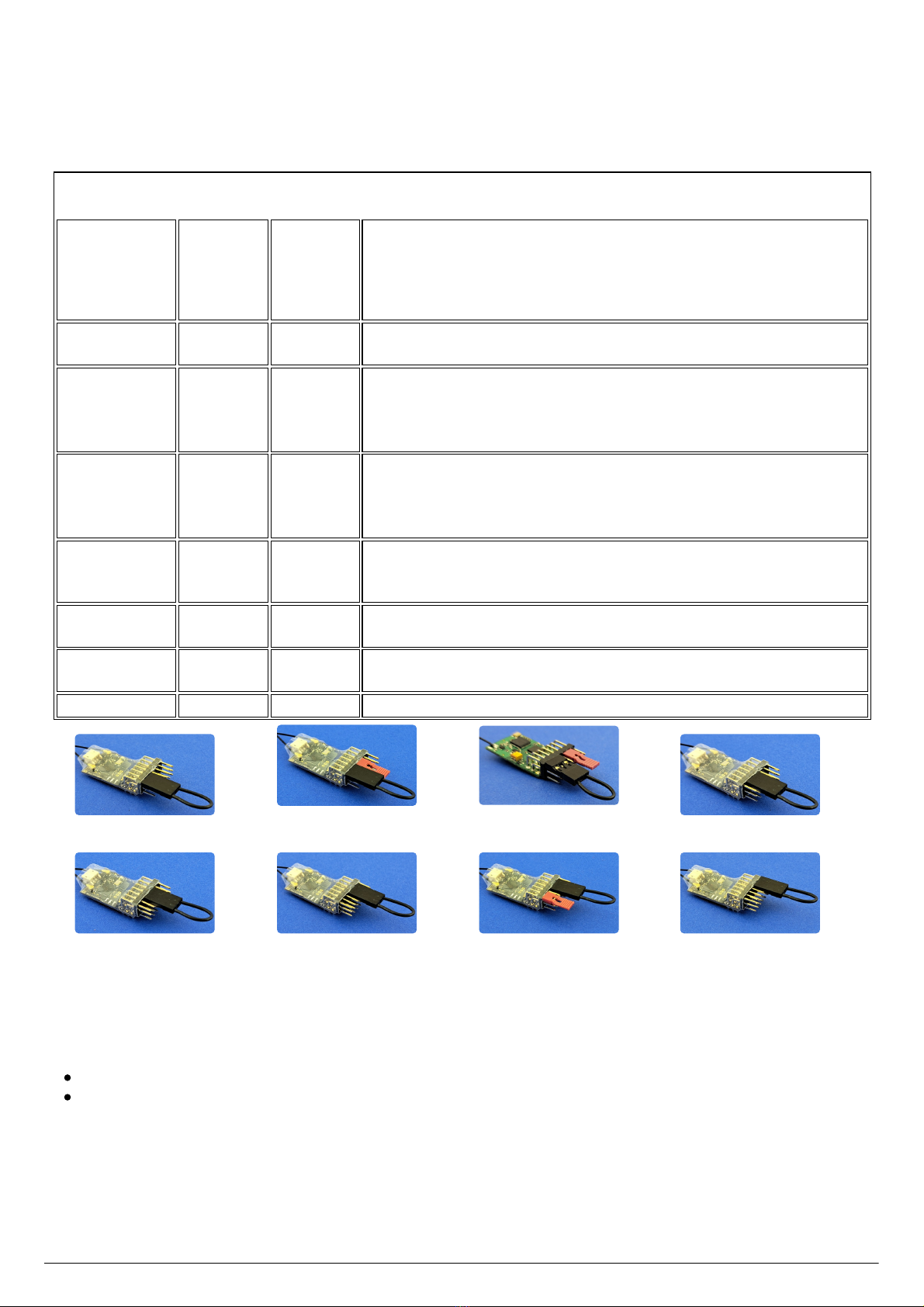
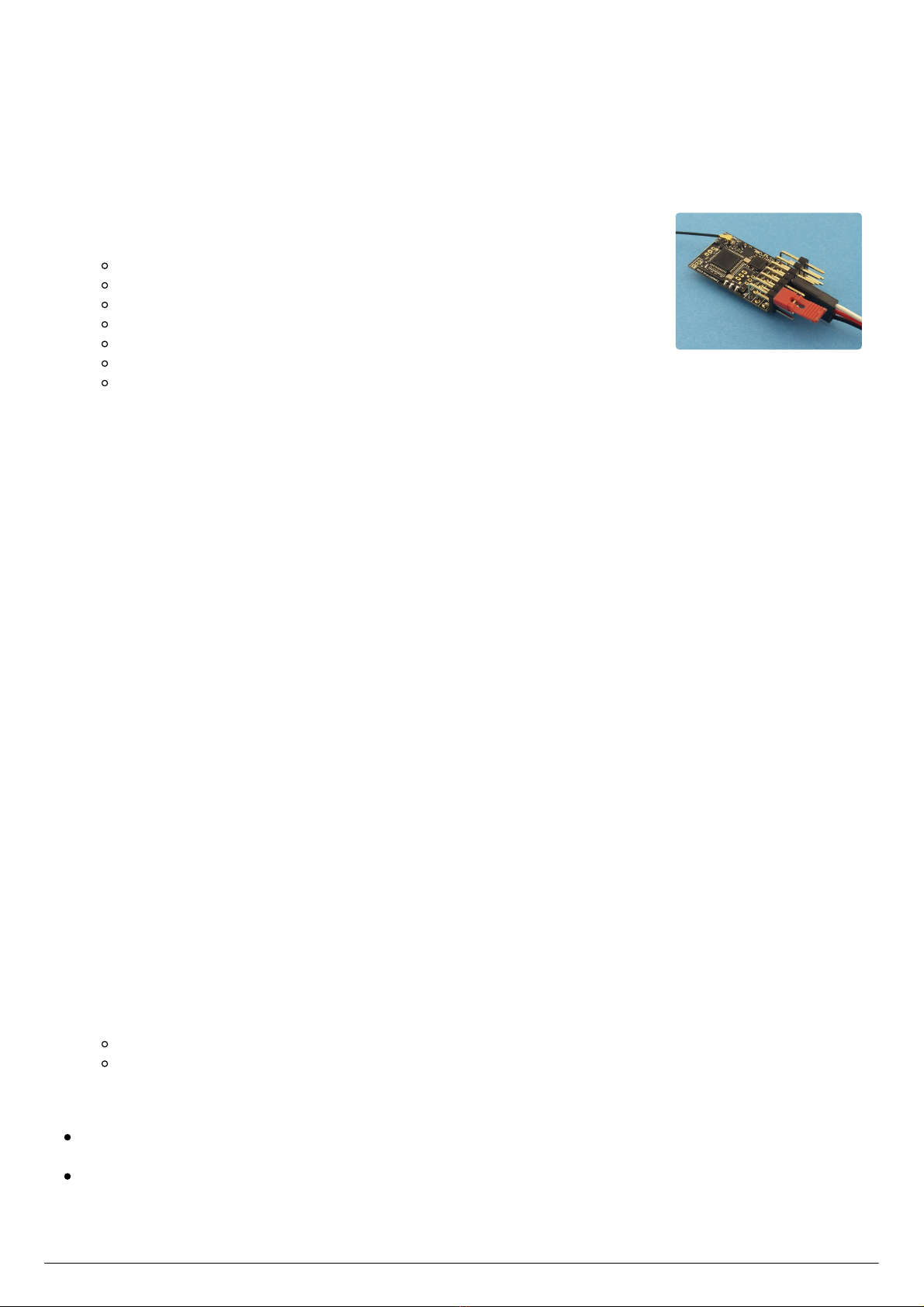
Use the small jumper plug to select a servo output to adjust. It is placed across the signal pin (top row) to be
adjusted and the adjacent signal pin. For example, to select P1 (throttle), place the small jumper plug across
signal pins 1 and 2 as shown in the image (the black connector in the image is the battery plugged into P4).
The standard MR001d setup has servo outputs on P1..P5. If your receiver has servo outputs on P6 and/or P7,
these may also be adjusted - P7 requires use of both small and large jumper plugs.
Steps:
1. MR001d must already be bound to your transmitter
2. receiver off and transmitter on
3. place the small jumper and then connect the battery:
P1: small on P1/P2, battery on P4
P2: small on P2/P3, battery on P4
P3: small on P3/P4, battery on P1
P4: small on P4/P5, battery on P1
P5: small on P5/P6, battery on P4
P6: small on P6/P7, battery on P4
P7: small on P1/P2 and large on P5/P7, battery on P4
4. the LED will flash a sequence twice to indicate the selected pin set and then flash rapidly - e.g. flash
pause flash pause rapid for P1, flash flash pause flash flash pause rapid for P2, and so on
Note: if the selected pin is not currently configured as a servo the LED will not flash the pin number
sequence and go immediately to rapid flashing; the receiver will not respond until it is switched off and
back on again
5. remove the small jumper plug when the LED is flashing rapidly, the LED will go off. Do not remove the
battery
6. connect a servo, this will respond to the transmitter control, no other output pin is active
The servo output is now selected. Jumper plugs are used on P6 and P7 (or P1 and P2 for adjusting P6 or P7)
to reverse the servo or adjust the travel end points. Reversing or end point adjustment can be repeated as
often as desired while the servo is selected. To stop the process, remove power from the receiver.
Reverse servo direction
The small jumper plug is placed across signal pins P6 and P7 (or P1 and P2 if adjusting a servo on P6 or P7).
Steps:
1. select servo output to adjust and plug servo in
2. place the small jumper across signal pins P6 and P7 (or P1 and P2 for a servo on P6 or P7)
3. the LED will flash rapidly
4. remove the jumper and the LED will stop flashing
5. the servo will respond to transmitter controls in the opposite direction to previous
The servo direction will reverse each time the procedure is executed.
Adjust servo travel
Servo travel end points can be increased or decreased using the large jumper plug on P6 (decrease) or P7
(increase) - P1 and P2 for servos on P6 or P7. The adjustment is done in small steps every ½ second and the
LED flashes for each step.
To make an adjustment:
1. move the servo to the low or high end using the transmitter control
2. use the large jumper to make changes:
on P6 to decrease the throw (P1 for servo on P6/P7)
on P7 to increase the throw (P2 for servo on P6/P7)
3. either remove the jumper or move the servo away from the end to stop the adjustment
The LED will stop flashing and the servo will stop moving when the adjustment limit is reached.
The limit for decrement is the mid point of travel so, if an end point is decreased to the maximum
amount, there will be no servo travel in that direction when the transmitter control is moved.
The limit for increment is the maximum signal value. Take care: not all servos will respond to the
maximum range of servo signal values; stop decrementing when the servo stops moving even though
the LED is still flashing.
Micron R/C, www.micronradiocontrol.co.uk, +44 (0)1653 696008 Micron MR001d Quick Start Guide : 4 of 4
Table of contents
Other Micron Radio Control Receiver manuals

Micron Radio Control
Micron Radio Control MR603a User manual

Micron Radio Control
Micron Radio Control MR603a User manual

Micron Radio Control
Micron Radio Control MR601a User manual

Micron Radio Control
Micron Radio Control MR603c User manual

Micron Radio Control
Micron Radio Control MR001c User manual

Micron Radio Control
Micron Radio Control MR6 Series User manual
Popular Receiver manuals by other brands

Multiplex
Multiplex RX-6 light M-LINK operating instructions

Sony
Sony DMX-NV1 (For DMX-NV1 model sold separately) Quick setup guide

ams AG
ams AG AS3932 Application note

Icom
Icom IC-R9000L Service manual

FTE Maximal
FTE Maximal MAX T200 HD Quick installation guide

Pioneer
Pioneer Elite VSX-44 quick start guide