Micron T 1287A User manual

• Low vibration air pump • Suits leaded & lead free solder (RoHS)
• Quality heating element • Rapid heat up
• LCD Touch Screen control interface
• Individual temperature & air flow adjustments
• Auto fan cooling extends element life • ESD safe • Zero switching
circuitry for spike suppression
T 1287A 1300W Hot Air
SMD Rework Station
Operating Instructions
INSIDE THE BOX
• T 1287A Workstation and air pump handle / pencil • Air pump handle stand •
3 Single pipe Nozzles: 8.5Ø, 6.5Ø, 5Ø • IC removing wire tool • Pliers (Tweezer)
– 5 piece set, non-magnetic, acid-resistant stainless steel • Mains Power Cord •
Instructions

3
Micron® 1300W Hot Air SMD Rework Station
OVERVIEW
Thank you for choosing the T 1287A SMD Rework Station – a great solution for your soldering equipment
needs! This tool is specically designed for soldering and desoldering Surface Mount Devices (SMDs) with
temperature controlled hot air. The T 1287A will achieve marked improvements in the quality and efciency
of your rework tasks. Please carefully read the operating manual prior to operation in order to maximize
the advantages of using your new T 1287A SMD rework station, and keep this manual readily accessible
for future reference.
WARNING: This appliance is not intended for use by children or inrm persons without assis-
tance or supervision if their physical, sensory or mental capabilities prevent them from using
it safely. Children should be supervised to ensure that they do not play with the appliance.
Failure to observe this safety regulation could result in a risk to life and limb. The manufactur-
er or supplier shall not be liable for damage resulting from misuse of the unit or unauthorised
alterations.
DESCRIPTION
The temperature-controlled T 1287A Hot-Air SMD rework station has been built around an intelligent
microcomputer chip, which is specially designed to work with lead-free SMD chips. The T1287A was
developed to meet the present and future Lead- free soldering needs of the electronic production industry
and suitable for work on professional SMD electronics. The many features of the T 1287A make it the
ideal tool for service and repair technicians as well as production line soldering operations.
This appliance is equipped with a high-power heating element that heats up quickly. High-quality sensors
and consistent heat-transfer technology ensure precise temperature regulation. The aluminum alloy hous-
ing is strong and acts as a reliable heat sink and is resistant to electro-magnetic interference. It also meets
RoHS standards requirement. The LCD touchscreen on the front panel provides a user with a clear vision
and convenient function setting controls. The temperature is maintained within +/-3° of its operating tem-
perature by a thermocouple sensor placed in the head of the heating element.
FEATURES
• Specially-designed intelligent microcomputer chip system. Comfortable and convenient operation.
• Easy to read digital LCD touch display with simple to use buttons to control temperature and air flow.
• Quick heating high-power element, with a maximum of 1300W.
• Ideally suited to desoldering ICs such as: SOIC, CHIP, QFP, PLCC, BGA etc. The built in static-free cir-
cuit design is safe for the sensitive circuit components elements like CMOS ICs.
• Air flow is shut off automatically when handpiece is placed in the cradle – 5sec cool down blow cycle.
• Auto-cooling design: When the power is switched off, the cooling system begins automatically.
• Heating element auto-protecting function: When the heating element reaches a high
temperature, this function automatically protects the element, thereby preventing the element
from premature failure.
CAUTION:
DO NOT WORK ON LIVE CIRCUITS
• Before working on any mains powered equipment, make sure that it is turned off, and the
mains plug is removed from the power point. You must not undertake work on live parts.
DO NOT USE IF DAMAGED
• If the power lead becomes damaged or the soldering station becomes faulty, discontinue use
immediately.

4
Micron® 1300W Hot Air SMD Rework Station
SAFETY PRECAUTIONS RECOMMENDED FOR OPERATION
1. Ensure the voltage rating of the unit and your power supply is identical prior to use.
2. Check carefully for any damage that may have occurred during transportation.
3. Put the product on a safe and stable working table. The surface should be made of fire and heat resist-
ant material, because the unit can reach very high temperatures and is potentially dangerous.
4. During the operation, the metal heater and nozzle is extremely hot, and will cause serious burns
if they make contact with exposed skin. Use gloves and/or any other heat resistant tools to pick
up the PCB assembly to eliminate the possibility of accidental burns.
5. Do not touch the unit or allow it to touch anything when in operation. Keep the nozzle and
heating element away from the body, clothes and flammable material when in operation.
6. Do not use the product near combustible gases or flammable materials that may ignite. Be sure
the work area is well ventilated.
7. Turn the power switch OFF and allow the heater to cool before checking or replacing the heater and
other parts, or prior to storing the unit. Do not modify the unit.
8. Do not block the air outlet of the nozzle, as this may damage the heating element.
9. This unit is designed for SMD rework and should not be used for any other purpose without first con-
sulting the manufacturer or its authorized agent. Suitable for SOIC, CHIP, QFP, PLCC, BGA etc.
10. To improve the operating life of the heating element, it is recommended that the unit not be used con-
tinuously at high temperature with a low air flow level. Let the heating element cool for up to 20 minutes
after using.
11. When the power is switched off, the unit will briefly continue to blow cooling air through the pipe. Do
not disconnect the plug during this cooling process. Ensure that it is placed back on its cradle to cool
down between rework operations. Also, do not press the green button on the hand tool while it is in the
cooling stand. Failure to comply with these instructions may result in damage to the hand tool.
12. Do not leave the machine unattended while switched on and operating. Turn off the machine
and unplug the power cord when you are leaving. Always place the hand tool in its holder when
not being used. The nozzle and the heating element remain hot after being switched off.
13. Do not use if damaged: If the pump stops working or the rework station becomes faulty,
immediately discontinue using the unit. Only authorized technicians are able to safely repair the
unit or replace parts.
14. Do not disassemble the pump. Please return to your vendor or its authorized repairers for
proper servicing.
TO PREVENT ELECTRICAL SHOCK, TAKE THESE PRECAUTIONS
1. Death or serious injury may result from electric shock. It is therefore essential to isolate the equipment
from the mains before commencing maintenance or repairs. Remember to unplug in the power cord.
2. Always connect the unit to a grounded power socket.
3. Do not pour water/liquids or subject the heating surface to physical shock. This may damage the heat-
er. Avoid contact with moisture.
4. The station must be switched off and the power cord must be unplugged before replacing the
fuse in the AC socket at the rear of the machine.
5. Turn the power switch off and remove the AC power cord by pulling the plug (not the cable) when the
unit will remain unused for a long period of time.
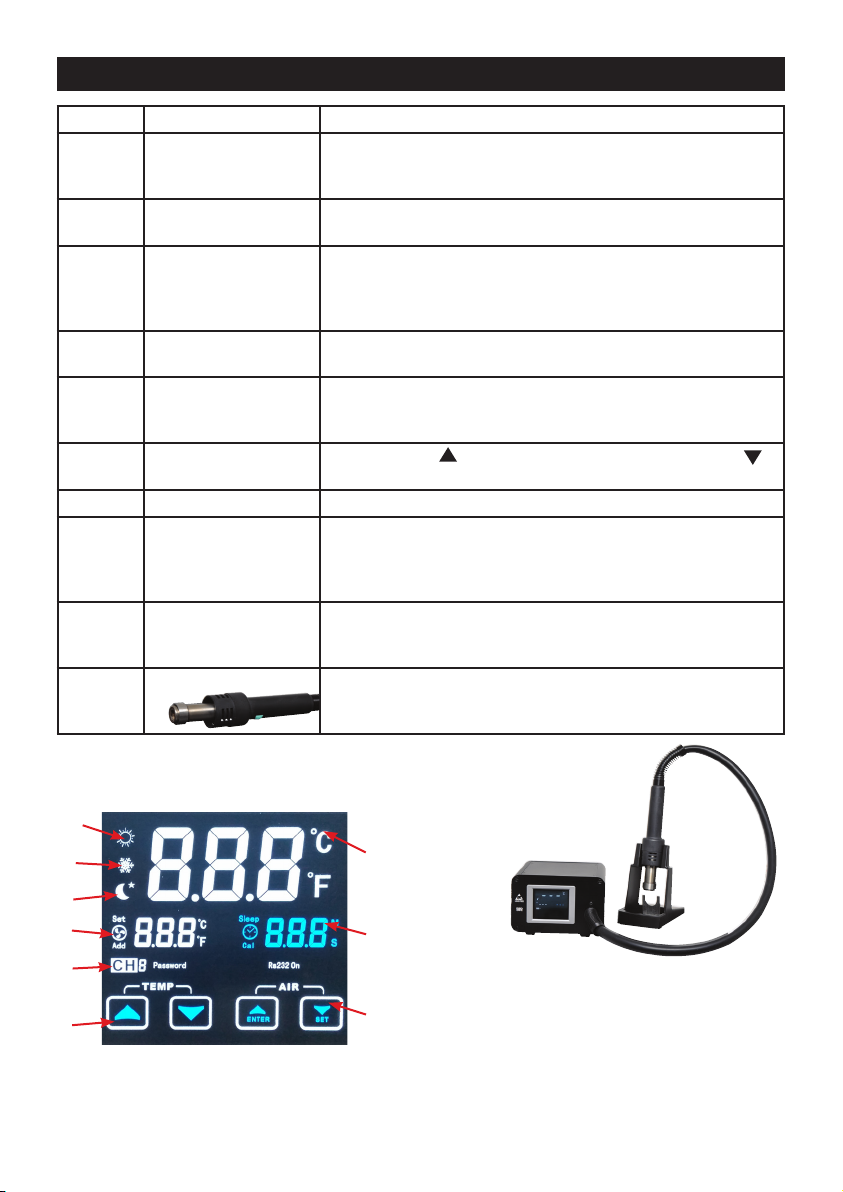
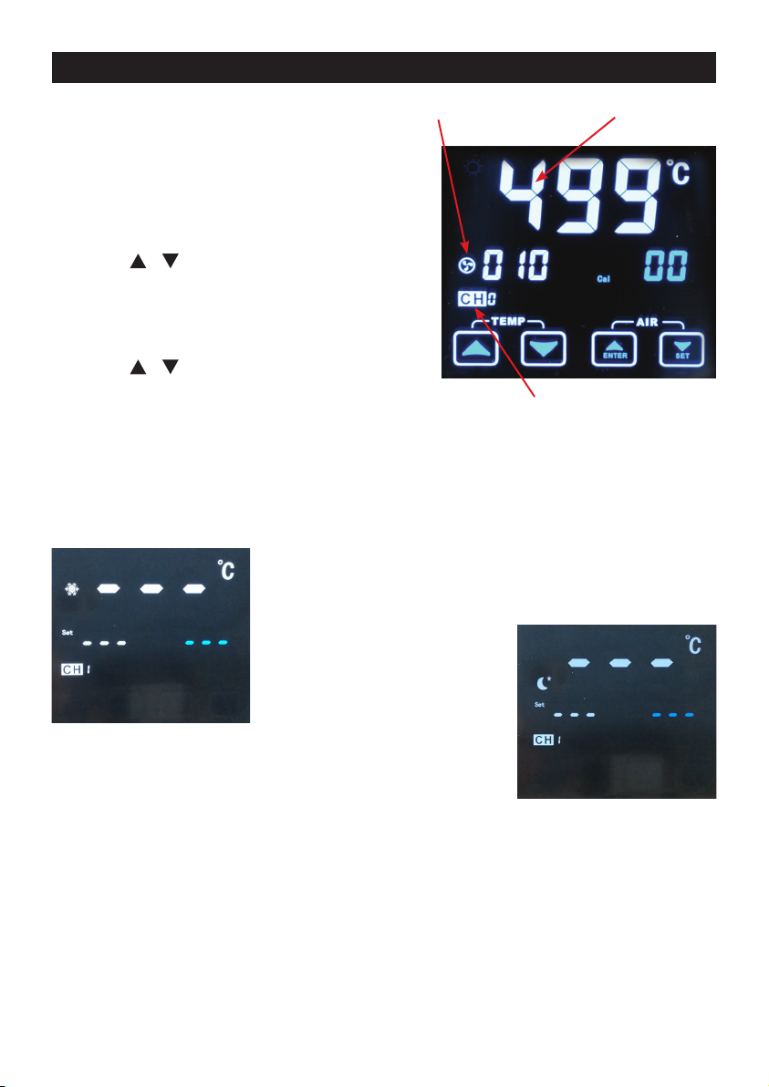
BOOTING UP
Plug the power cord connector into the AC socket on the back of the machine, and plug the power cord
into a mains power outlet. Boot is executed with CH0 program. You can adjust the temperature and air
volume. If you want to use CH1-CH3 program, please press the green button on the handle to scroll
through to start the CH1/CH2/CH3 setting. Each CH program in the loop is slightly different – see below.

5
Micron® 1300W Hot Air SMD Rework Station
1
2
3
4
5
6
7
8
9
Figure 1: Boot Screen
Touchscreen
Figure 2: Unit in standby
with handle in cradle
No. FUNCTION DESCRIPTION
1 Heating (Sun Icon) Sunlight icon shows that the element is heating up, temperature
increases. When it ashes, it shows that the temperature is being
maintained at the set temperature.
2 Cooling (Snowflake) When it appears on screen, it shows that they element is cooling
down, decreasing temperature. The fan may be whirring rapidly.
3 Standby (Moon Icon) When it appears on screen it shows that the element is in stand-
by / sleep mode, and the Hot Air nozzle is possibly at or near
room temperature. CAUTION – metal parts of blower might be
still hot!
4Air Flow Reading Use the arrow buttons under ‘AIR’ to set the rate of airow from
0 to 2000cm3/sec (120L/MIN).
5 Channel Preset CH1, CH2, CH3 preset temperature setting accessed by press-
ing the green button on the hand tool. CH0 is default operating
mode.
6 Adjust Temperature Press Up arrow to increase set temperature, down arrow
to decrease.
7 Display Temperature As set by user using arrows.
8 ‘Cal’ - Correction Value Used to calibrate the heating element. The ‘CAL’ function is ac-
cessed by pressing SET on the LCD touchscreen with the green
button on the handle. CAL requires a soldering iron thermometer
and is not recommended.
9 Set & Enter Press SET to activate Channel presets, and activate Cal function.
Press ENTER to conrm the temperature and airow once set for
a channel.
10 Channel Preset Select Press the green button on the blower handle to select which CH
you wish to use or adjust. Scrolls through Channels CH1 – CH3
in a loop.
NOTE: From any preset CH setting, just tap the adjust temperature arrows and the CH0 default
activates. It remains the default channel for temperature control, unless a channel preset is again
activated by pressing the green button on the handle.
1. Heating
2. Cooling
3. Standby
4. Air Flow
5. Preset Channel
6. Adjust Temperature
7. Display Temperature
8. Cal- Correction Value
9. Set & Enter or control Air flow rate

6
Micron® 1300W Hot Air SMD Rework Station
OPERATING PROCEDURES
1. Ensure that the base unit power switch is in the “OFF”
position. Next connect AC power cord.
2. Turn mains power switch to “ON” position. The LCD
touch screen will illuminate many icons, most of which are
non-functioning indicators. Those icons described in the
functions table above are the symbols for functions that are
enabled on this model. (See Figure 1)
3. Press the or button for temp to set. CH0 displayed
as the default channel. (CH0 is NOT a preset channel and
has no memory storage.)
4. The display temperature will climb steadily (or decrease)
as indicated by the ashing sunlight icon. When icon almost
disappears, the set temperature has been reached.
5. Press the or button for the AIR to set the fan ow
rate. You will hear the fan speed and pitch change.
Temp
Channel 0
displayed
Air Flow Rate
SLEEP MODE
Option 1: Press and hold the green button on the handle for three seconds (while the handle is NOT
in the cradle
Option 2: Place the handle onto the cradle.
Stage 1: The air ow fan is fully opened for a few seconds to quickly
cool the heater core temperature to below 100 °C. The display screen
shows the ‘SNOWFLAKE’ icon in the top left corner while the fan is
whirring.
Stage 2: The air ow fan stops and
the ‘CRESCENT MOON’ icon replaces
the ‘SNOWFLAKE’, indicating that the
device has entered sleep mode or hiber-
nation. To exit Sleep Mode, either press
the green button again to reactivate the
station, or simply remove the gun from
the cradle and the air ow and heating
functions will recommence.
To exit Sleep Mode, either press the green button again to reactivate the station, or simply remove
the gun from the cradle and the air ow and heating functions will recommence.
NOTE: Sleep mode is the default mode when the device is rst switched on with the handle
standing in the cradle. Lift the handle out of the cradle and the station will begin heating up to
whatever was the last used temperature.
OPERATING PRECAUTIONS
• Make sure both heater and nozzle are cool before attaching the nozzle.
• Air Nozzle Replacement: Use the U-shaped piece at the front of the iron stand to remove the Air
Nozzle. Please use needle-nosed pliers to install a new desoldering head or nozzle.

7
Micron® 1300W Hot Air SMD Rework Station
• Initially, the nozzle may emit white smoke, but this will soon dissipate.
• Never allow the hot air to blow against your skin. Never point the nozzle at anyone when using
the device. Keep the hot air from the nozzle away from the eyes and face.
• When the power cord is connected to the mains power supply, there is a little electricity flowing
into the unit; even though the power switch is in the off position. So when you don’t use the unit
for a longer period of time, disconnect the plug.
OPERATION SETUP
1. Select the Nozzle that matches the size of the IC. Attach the nozzle when both the heating element and
the nozzle are cool and the unit is turned off and unplugged.
2. Loosen the screw on the nozzle. Attach the preferred nozzle.
IMPORTANT: Do not force the nozzle or pull on the edge of the nozzle with pliers. Also, do not tighten the
set-screw too tightly.
Factory Setting:
• CH1. Temperature 150°C air volume 100- (1000cm3/sec)
• CH2. Temperature 300°C air volume 150- (1500cm3/sec)
• CH3. Temperature 450°C air volume 200- (2000cm3/sec)
PROGRAM SETTINGS: CH1 / CH2 / CH3
This touchscreen model has a memory for three pre-set temperature levels – CH1, CH2, CH3. These
channels are accessed by pressing the green button on the blower handle. Each time you press this
button, the screen with scroll to the next CH number in sequence, and eventually loop back to CH1.
Follow these steps to access the different programs available on this unit.
1. While pressing the SET button on the screen and the green button on the handle for two seconds, the
blue ‘00’ number on the LCD starts to flash after the buttons are released.
2. This number is used for the calibration temperature. If you do not need to calibrate the temperature,
press the SET button and the CH1 and temperature will start to flash. Use the and arrow symbols
under the CH icon to adjust to the required temperature.
3. When the unit reaches the desired temperature, please press the SET button again to switch to
the air flow adjustment. The number below the CH1 starts to flash and the air flow volume can
be adjusted from 0-200cm3/sec.
4. Press SET again to adjust the temperature of CH2, and then press SET once more to adjust the
air volume of CH2. Follow the same pattern to set the temperature and air flow parameters for
CH3.
5. At the end of this sequence of settings, press SET one final time to switch the display between °C
or °F units. Whichever units are flashing on screen, a single touch of any arrow will change it to
the other units for temperature measurement.
6. After all the program settings have been determined, press ENTER to complete and store the
new parameters. Alternatively, if you just needed to adjust one of the three channels, then you
can change the temperature and air flow settings for that channel and simply press enter to
store them.
NOTE: To protect the life of the heater, the air volume should never be set to zero when the
heating element is on. It is recommended that the higher the temperature, the higher the air
flow should be.

8
Micron® 1300W Hot Air SMD Rework Station
QFP (QUAD FLAT PACKAGE) DE-SOLDERING FOR ICS
1. Melt the solder: Hold the iron so that the nozzle is located directly over but not touching the IC, and
allow the hot air to melt the solder. Be careful not to touch the leads of the IC with the nozzle.
2. Remove the IC: Once the solder has melted, remove the IC by lifting it out with the pliers
(tweezers). NOTE: For SOIC, PLCC etc., please use tweezers to desolder.
3. Turn the power switch off: After the power is switched off, an automatic blowing function begins send-
ing cool air through the pipe, in order to cool both the heating element and the handle. So do not discon-
nect the plug during this cooling process.
NOTE: About a minute after the power is switched off, the temperature will drop to 75°C (167°
F), and the power will automatically shut off.
4. Remove any remaining solder: After removing the IC, clean the remaining solder chips with a wick or
desoldering tool.
QFP SOLDERING
1. Apply the solder paste: Apply the proper quantity of solder paste and flux (preferably no-clean) and
place the SMD on the PCB.
2. Preheat SMD.
3. Soldering: Heat the lead frame evenly.
4. Washing: When soldering is completed, wash the area with a defluxer.
NOTE: While there are many advantages of hot air SMD rework, it is also possible to have defects
for soldering BGA. It is recommended that all soldering joints be closely inspected.
To meet RoHS (European requirement for lead-free solder), the 60/40 solder alloys are not allowed
in the production process. The RoHS lead-free solder alloys require a working temperature of
about 30°C (54°F) higher than typical 60/40 lead/tin soldering.
GENERAL CLEANING
The outer cover of the iron and station may be cleaned with a damp cloth using small amounts of
liquid detergent. Never submerse the unit in liquid or allow any liquid to enter the case of the station.
Never use any solvent to clean the case.
SPECIFICATIONS
Model T 1287A
Input 220 - 240 VAC ~ 50 Hz
Output 1300 W
Fuse (Fast type) 10A
Temperature Range 100°C - 500°C
Air Flow Rate 0-2000cm3/sec (120L/MIN)
Temperature correction Range (CAL): +99°~ -99°C
Default Set: 200°C
Temperature correction value: “00”
Dimensions 157 x 102 x 150 mm (W x H x D)
Weight 2.5 kg

1
Micron® 1300W Hot Air SMD Rework Station
Distributed by Altronic Distributors Pty. Ltd.
• Perth • Sydney • Melbourne
Phone: 1300 780 999 Fax: 1300 790 999
altronics.com.au
Altronic Distributors warrants this product for one year from date of purchase from Altronics or its resellers
to the consumer. If this item is part of an installation or another product, please contact the installer or
supplier for your warranty.
During the warranty period, we undertake to repair or replace your product at no charge if found to be
defective due to a manufacturing fault. The warranty excludes damage by misuse or incorrect installation
(i.e. failure to install and operate device according to specifications in the supplied instruction manual),
neglect, shipping accident, or no fault found, nor by use in a way or manner not intended by the supplier.
For speakers, misuse includes burnt out voice coils.
For repair or service please contact your PLACE OF PURCHASE.
If this item was purchased directly from Altronics please make a warranty claim by:
1. FOR MAIL ORDER CUSTOMERS (includes school and trade orders),
a) Ringing us on 1300 797 007 and quoting your tax invoice number.
b) Upon contacting Altronics, we will issue an R.A. (Return Authorisation). As Altronics have a
number of service agents throughout Australia, a copy of the R.A. will be emailed, faxed or mailed to
you with full instructions of how and where to send the goods. The freight for shipping goods back to
Altronics for all repairs is at the customer’s expense.
c) A copy of the R.A. form, (or at the very minimum, the R.A. number) must accompany the goods to
effect the repair.
d) Altronics will pay the return freight to the customer where the warranty claim has been accepted.
e) Please quote the R.A. number in any correspondence to us.
2. FOR OVER THE COUNTER PURCHASES; to make a warranty claim, please return the goods
to us in any of our stores, with a copy of your proof of purchase (tax invoice).
a) Upon leaving the goods at one of our stores, an R.A. number will be issued to you.
b) Once repaired, you will be contacted, advising that the goods are ready to be collected from
the store.
It is at Altronics discretion as to whether the goods will be repaired or replaced (whilst under
warranty); and as to whether identical goods will be used to replace the item due to changes of
models / products.
Note: Under no circumstances should you attempt to repair the device yourself or via a non-
authorised Altronics service centre, as this will invalidate the warranty!
Our goods come with guarantees that cannot be excluded under the Australian Consumer Law. You
are entitled to a replacement or refund for a major failure and for compensation for any other reasonably
foreseeable loss or damage. You are also entitled to have the goods repaired or replaced if the goods fail
to be of acceptable quality and the failure does not amount to a major failure.
Table of contents
Other Micron Power Tools manuals