Sturtevant Richmont SLTCR-FM 2.4GHz 3000I User manual
Sturtevant Richmont
The Tools You Trust
555 Kimberly Drive Carol Stream, IL 60188
Phones Worldwide: +1 847/455-8677
Toll Free US Only: 800/877-1347
Fax: 847/455-0347
www.srtorque.com
SLTC24-FM (2.4GHz) Torque Wrench Operating Instructions
Models to which these instructions apply: P/N Description P/N Description
810417 SLTC-FM 2.4GHz 3600I 810418 SLTC-FM 2.4GHz 4800I
P/N Description
810416 SLTCR-FM 2.4GHz 3000I
810419 SLTCR-FM 2.4GHz 7200I
S/R SLTC-FM 2.4 GHz torque wrenches are designed and manufactured to provide consistent torque application in
multiple manufacturing and maintenance applications. They meet or exceed the requirements of ASME B107.300-
2010 and ISO 6789. These wrenches are accurate to +/-4% of the preset value from 20% to 100% of rated
capacity.
Interchangeable Heads and Dovetail
Any S/R interchangeable head may be used with the wrench. Note: It is imperative that the head used to preset the
torque wrench have the same common centerline length as the head that will be used in assembly. Failure to do so
will create a different torque output during assembly than that which was preset. To attach the head:
1. Align the head with the dovetail and slide it onto the dovetail until it contacts the retaining pin.
2. Use a small hex key or other device to depress the locking pin.
3. Slide the head completely onto the dovetail.
To remove the interchangeable head:
1. Use small hex key or similar device to depress the locking pin through the access hole in the rear of the
head.
2. While the pin is depressed, slide the head sideways to hold the pin down and remove the hex key.
3. Slide the head completely off the dovetail.
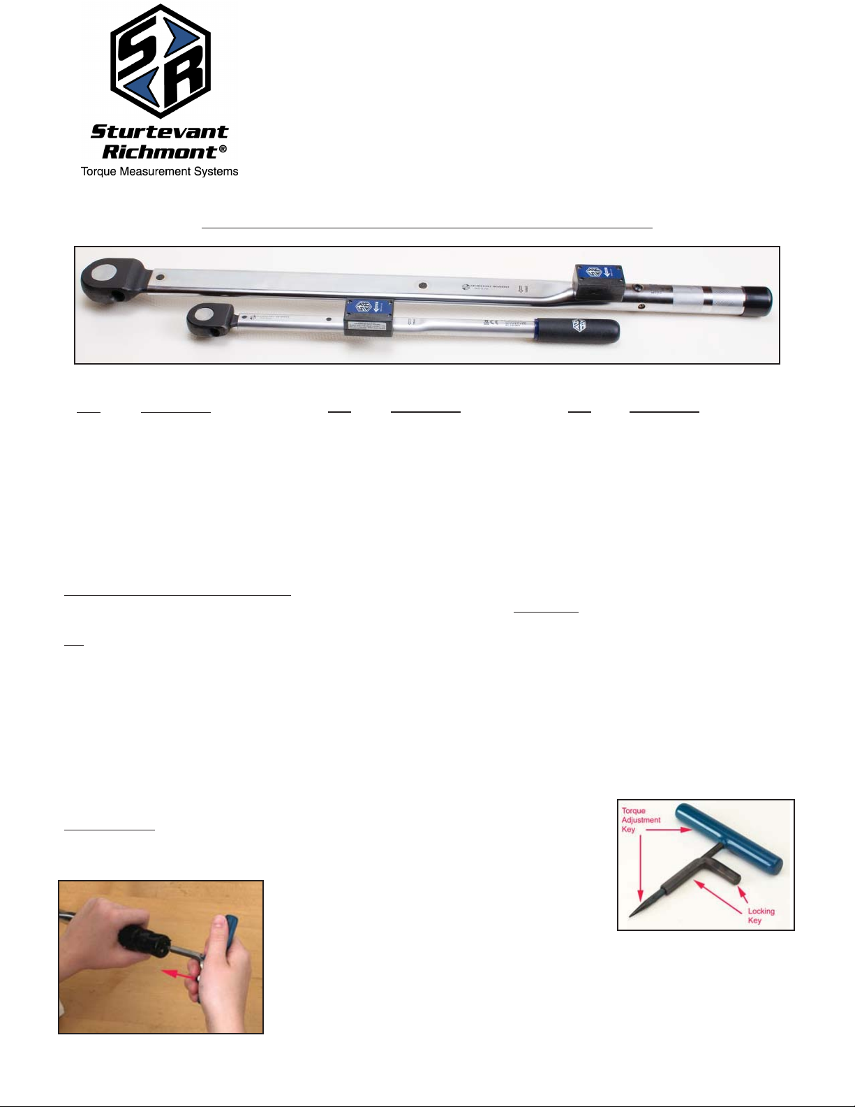
Torque Setting
A torque tester of +/- 1% indicated value accuracy or better, an S/R CART (Combination
Adjusting and Release Tool shown at right), and an interchangeable head having the
same common centerline length as the head that will be
used in assembly and capable of engaging the tester
are required.
1.Remove the protective cap and insert the Torque Adjustment Key fully into the
rear of the wrench so the hex engages the adjustment nut. Do not engage the
Lock Key. Rotate the Torque Adjustment Key slightly clockwise to disengage the
adjustment nut from the lock nut.
P/N 857331 B Revised 6/30/15
2. Slide the Lock Key in until it engages the lock nut. You may need to rotate the lock
key slightly to align it with the internal hex of the lock nut. Rotate the Lock Key
counterclockwise several turns to assure the lock nut is fully disengaged from the
adjustment nut and that there is sufficient travel available for the adjustment nut to
attain the torque setting desired.
3. Install the interchangeable head on the wrench. Engage the wrench to the tester
and click the wrench once or
twice while noting the
readings. To adjust the
wrench to a higher torque
setting, rotate the Torque
Adjustment Key clockwise. To
adjust the wrench to a lower
torque setting, rotate the
Torque Adjustment Key
counter-clockwise. Torque
adjustments should be made
in small increments with
several checks made
between each movement of the Torque Adjustment Key.
4. Once the desired torque has been attained, hold the Torque Adjustment Key steady and rotate the Lock Key
clockwise until the lock nut firmly engages the torque adjustment nut, locking it in place. Remove the CART from
the wrench and perform a final torque check on the tester. When the reading matches the desired torque and the
lock nut is firmly engaged to the torque adjustment nut, the procedure is complete.
Radio Communications - 2.4 GHz Communication Overview
These tools use the 2.4GHz band for communication with the controller. As with all radio communications, there are
limits on the distance at which reliable bi-directional communication may be obtained. Physical barriers such as steel
framing, sheet metal and other objects that impede radio waves can significantly reduce the reliable communication
distance. Another factor affecting the reliability and distance combination is the radio environment in which the unit will
be used.
The controller and torque wrench may operate on any of the 12 channels these products use. It is generally best to
think about this even before the unit is installed.
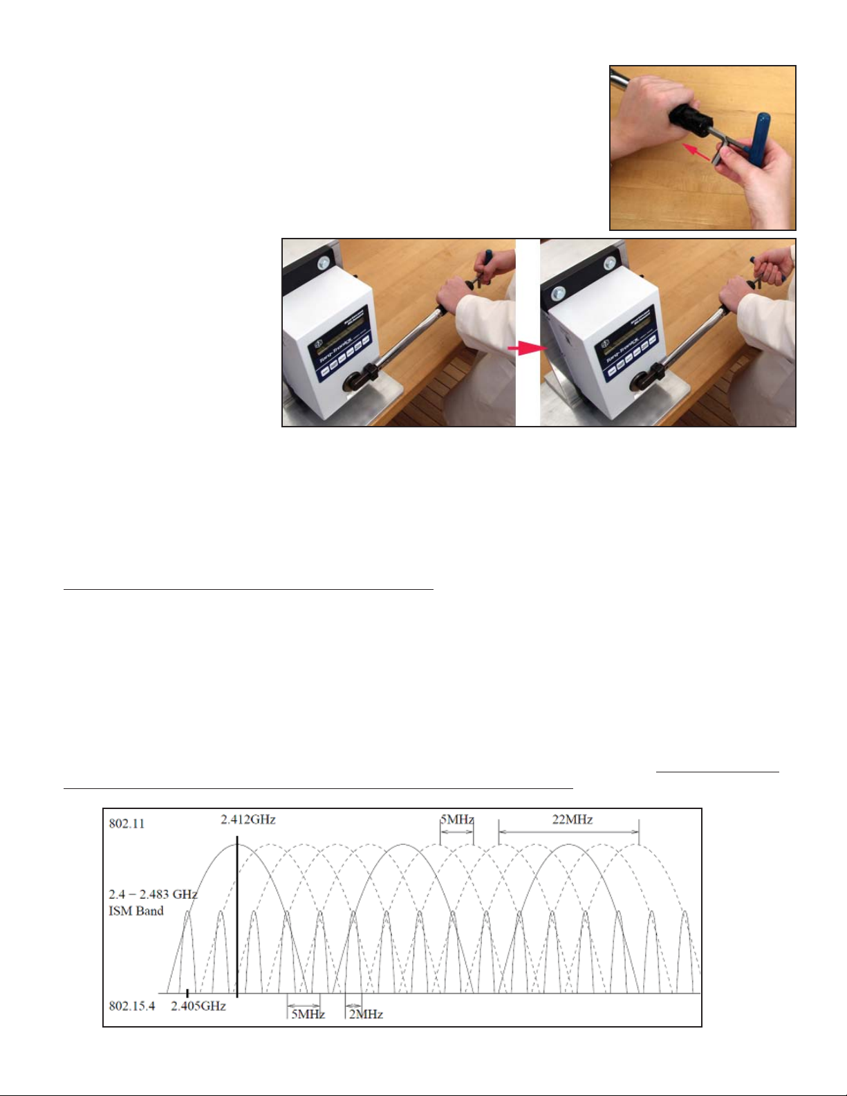
The radio modules in the controllers and torque wrenches used with them comply with the IEEE 802.15.4 standard.
The channel numbers loosely match the channels used by the IEEE 802.11b/g WLAN standard. It may be beneficial
to use channels that do not match the channels used by a nearby wireless network. The graph below depicts both
standards and illustrates the center frequencies and channel overlap for each standard.
P/N 857331 B Revised 6/30/15

Notice that the channels we use leave a much smaller footprint than WLAN. Also notice that one WLAN channel
radiates a significant amount of energy onto several of the
adjacent WLAN and controller channels.
For the most reliable communication between the S/R controller
and the tool in a 802.11b/g LAN environment, it is usually best
to choose a channel for the controller and tool that is separated
from the channel of the LAN.
Unlike IEEE 802.15.1 (Bluetooth) radios, the our 2.4GHz radio
modules do not frequency hop, use less power and have faster
response times with less impact on other wireless devices. A
wrench only transmits a small packet of data after each torque
operation, and each transmission lasts about 30ms (0.03 sec-
onds).
The 2.4GHz radio used by the unit and the tool is certified in
the United States (FCC), Canada (IC), and Europe (CE).
Torque wrench output power: 1mw
Controller 2.4GHz output power: 10-60mw
Typical 802.11b/g output power: 100mw
Establishing RF Communication With S/R Controllers
The procedure used to establish RF communication with the SR controllers varies by controller. Regardless of the
controller, however, there are two important elements to understand and one procedure that it is useful to know.
The first element is that the system uses the identification number of the transceivers in establishing
communications. The transceiver in the controller and the one in the torque wrench each have identification
numbers. When communication between the two is first established, the numbers are exchanged and stored in
memory. The controller and tool will thereafter ignore communications from other radios until the number stored in
memory is replaced with a different identification number.
The second element is that under all conditions the controller and the tool to be used with it must be on the same
channel. If the channel on the controller is changed and the channel on the tool is not, they will not communicate or
will cease communicating if they have previously been associated with each other.
To remove the identification of the TV unit from the tool memory, click the wrench and hold it in the clicked position
until the LED on the wrench flashes. This will take about 5 seconds. Release the pressure on the tool and allow it to
return to the normal position.
The flashing of the LED occurs when the memory of which controller the tool was associated with has been erased.
The tool is now ready to be associated with another controller.
Note that when the battery has been removed and replaced in the wrench the LED will alternate between emitting
red and green light several times very quickly. If the alternating color emission stops and then a red light pulse is
emitted, the tool is not associated with a specific controller and can be associated with whatever unit is desired. If
the alternating color emission stops and then a green light pulse is emitted, the tool has a specific controller unit
identification number in memory and is ready to be used with that unit.
To establish communication with the controller, it is necessary to follow the instructions included with the specific
controller to be used. The simpler controllers use one methodology, and those with advanced features in their
programs use another.
Frequency Map of 802.15.4 vs. 802.11b/g
Center Frequency (GHz)
Channel 802.15.4 802.11b/g
1 2.410 2.412
2 2.415 2.417
3 2.420 2.422
4 2.425 2.427
5 2.430 2.432
6 2.435 2.437
7 2.440 2.442
8 2.445 2.447
9 2.450 2.452
10 2.455 2.457
11 2.460 2.462
12 2.465
P/N 857331 B Revised 6/30/15
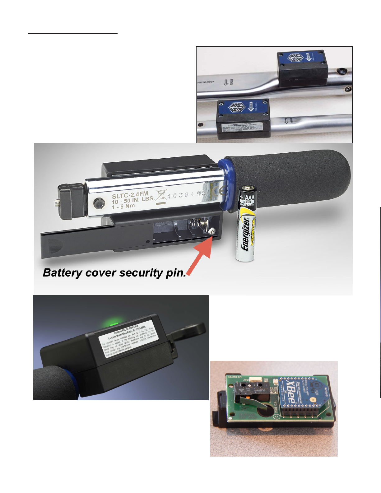
Battery Installation/Replacement
These tools are shipped with the correct battery for proper function included. To access the electronics and battery
holder:
1. To access the compartment, use a #1 Phillips
screwdriver to depress the battery cover security pin.
Slide the battery cover back to reveal the battery.
2. While inserting new battery in the battery compartment
please be sure to respect polarity requirements. .
3. Slide the cover back to closed. You will feel the cover
security pin close.
4. Return to work.
Please note the new raised, Fresnel provides
greater visibility from almost all angles.
The A3 Radio Board Shown to the Right.
P/N 857331 B Revised 6/30/15

If it ever becomes necessary to replace the circuit board, us the first two steps of the battery replacement procedure to
gain access to the board. Remove the old board and replace with the new. We strongly advise replacing the insulating
paper at the same time to assure electrical integrity is maintained.
Operation & LED's
Once the tool has been preset, the appropriate interchangeable head installed and the radio transceiver has been
associated with the appropriate controller and specifications exchanged, the tool is ready for use. In normal operation,
the tool will emit a strong tactile and sound impulse when it clicks. If the tool is jerked (too little time in the clicked
position) the LED on the tool will not illuminate. If the tool has been properly used (force applied, click attained, force
released within specified time frame) the LED on the circuit board will illuminate with a green color. This will shine
through the cover and be highly visible. If the tool has been pulled past the click (too much time in the clicked position)
the LED on the circuit board will illuminate with a red color. Under either of the latter two circumstances, the information
will be immediately transmitted to the controller.
SLTCR (Ratcheting) Models
These tools use the SR slide pin ratchet design to permit the user to reposition the body of the tool in limited-access
applications where a socket is used. Even though the ratchet is reversible, the tool only applies measured and
controlled torque in the clockwise direction, so thought must be given to the task to be accomplished before the ratchet
is reversed and the tool used in the counter-clockwise direction. Exceeding the capacity of the tool in a CCW torque
application is likely to damage the tool and is not covered by warranty.
The ratchet should be disassembled and cleaned periodically, then the ratchet spindle teeth lubricated very lightly with
a grease containing molybdenum disulfide prior to reassembly. For detailed instructions on ratchet disassembly,
cleaning and reassembly, go to the FAQ section of our website.
SAFETY
•ALWAYS wear safety glasses and all other required safety equipment when operating this tool.
•Do NOT exceed the rated capacity of the wrench.
•Do NOT use this wrench for any purpose other than that for which it was designed and manufactured.
Cleaning
This wrench should be cleaned with a soft cloth dampened with water. Do not immerse this tool in liquid or use any
solvent other than water to clean the tool.
Presetting, Calibration and Repair
Factory presetting and calibration from our ISO 17025 Accredited Calibration Laboratory are available. Parts and
factory repair are also available. Contact your SR sales professional for details.
INSTRUCTION TO THE USER
This equipment has been tested and found to comply with the limits for a class B digital device, pursuant to part 15
of the FCC Rules. These limits are designed to provide reasonable protection against harmful interference in a resi-
dential installation. This equipment generates, uses and can radiate radio frequency energy and if not installed and
used in accordance with the instructions, may cause harmful interference to radio communications. However, there is
no guarantee that interference will not occur in a particular installation. If this equipment does cause harmful interfer-
ence to radio or television reception, which can be determined by turning the equipment off and on, the user is
encouraged to try to correct the interference by one or more of the following measures:
* Reorient or relocate the receiving antenna.
* Increase the separation between the equipment and receiver.
* Connect the equipment into an outlet on a circuit different from that to which the receiver is connected.
* Consult the dealer or an experienced radio/TV technician for help.
Additional Information
Additional information is available seven days a week from our website, www.srtorque.com. You can also contact us
via phone at 847-455-8677 or email us at [email protected]
P/N 857331 Rev B Revised 6/30/15
This manual suits for next models
4
Table of contents
Other Sturtevant Richmont Power Tools manuals

Sturtevant Richmont
Sturtevant Richmont SLTC-FM 2.4GHz Series User manual

Sturtevant Richmont
Sturtevant Richmont exacta 2 User manual

Sturtevant Richmont
Sturtevant Richmont SDR Series User manual

Sturtevant Richmont
Sturtevant Richmont SLTC Series Operating instructions

Sturtevant Richmont
Sturtevant Richmont SD Series User manual

Sturtevant Richmont
Sturtevant Richmont DTC User manual

Sturtevant Richmont
Sturtevant Richmont exacta 2 Service manual

Sturtevant Richmont
Sturtevant Richmont exacta 2 3000 series Service manual

Sturtevant Richmont
Sturtevant Richmont exacta 2 Programming manual

Sturtevant Richmont
Sturtevant Richmont LTCR Series User manual


