micronel U100HL-024KA-4 User manual

1 of 17
All data can be subject to change without advanced notice. Version: December 6, 2018. © Micronel AG
Original Operating Manual - German
OPERATING MANUAL U100HL-024KA-4
Micronel AG
Zürcherstrasse 51
CH-8317 Tagelswangen
Switzerland

2 of 17
All data can be subject to change without advanced notice. Version: December 6, 2018. © Micronel AG
Contents
1 Important Information ......................................................................................................... 3
1.1 About This Manual....................................................................................................... 3
1.2 Depiction of Warning Notices....................................................................................... 3
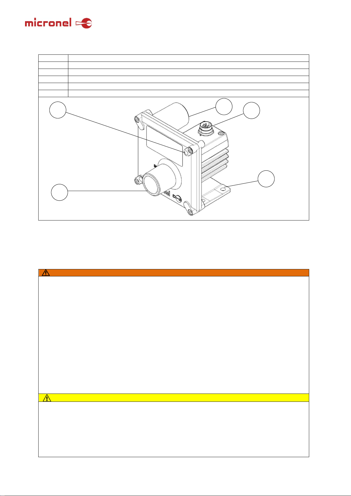
2 Overview of U100HL-024KA-4 ........................................................................................... 4
3 Basic Safety Information..................................................................................................... 4
4 Intended Use...................................................................................................................... 5
4.1 Improper Use............................................................................................................... 6
5 Technical Specifications..................................................................................................... 6
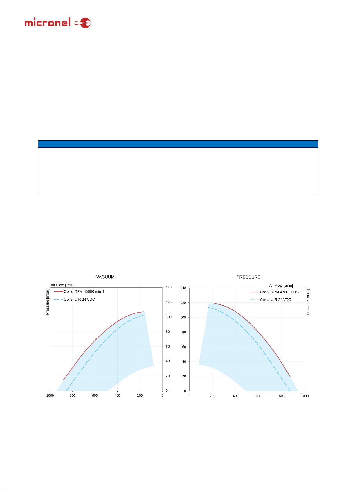
5.1 Performance Fields...................................................................................................... 6
5.2 Mechanical Nominal and Threshold Values of the Blower............................................ 7
5.3.1 Dimensions............................................................................................................ 7
5.3.2 Nominal and Threshold Values of the Blower........................................................ 8
5.4.1 Materials................................................................................................................ 8
5.5.1 Mounting .............................................................................................................. 9
5.5.2 Sound and Vibration Dampening........................................................................... 9
6 Connections....................................................................................................................... 9
6.1.1 Structure of the Internal Electronics......................................................................10
6.1.2 Pin Assignment ....................................................................................................11
6.1.3 Electronic Functions.............................................................................................11
6.2. Pipe and Hose Connections.......................................................................................12
7 Initial Commissioning.........................................................................................................13
9 Cleaning Maintenance.......................................................................................................15
9.1 Inspection................................................................................................................16
9.2 Lubrication..................................................................................................................16
9.3 Troubleshooting..........................................................................................................16
10 Transport.........................................................................................................................17
11 Storage............................................................................................................................17
12 Disposal ..........................................................................................................................17

3 of 17
All data can be subject to change without advanced notice. Version: December 6, 2018. © Micronel AG
1 Important Information
1.1 About This Manual
This manual contains important information for the safe and intended use of this product.
This manual is an integral part of the product and must be kept accessible to operating personnel at
the site of use of the U100HL-024KA-4 at all times.
Qualified personnel must read and understand this manual before starting any work. The prerequisite
for safe work is the observance of all safety instructions in this manual.
Illustrations in this manual are provided for basic understanding and may differ from the actual
design.
Please check to see if the manual is available in a revised version or in your language.
www.micronel.com/service-navi/download/operating-manuals
1.2 Depiction of Warning Notices
WARNING
Non-compliance may cause severe injuries and even death.
CAUTION
Non-compliance may cause minor to moderate injuries.
NOTE
Information for preventing material damage.
Environmental Protection
Information on the environmentally-friendly disposal of packaging materials, waste,
auxiliary materials and consumables at the end of the product’s service life.

4 of 17
All data can be subject to change without advanced notice. Version: December 6, 2018. © Micronel AG
2 Overview of U100HL-024KA-4
Position
Designation
1
Pressure discharge nozzles, outlet, G 3/4 inches
2
Suction nozzles, inlet, G 3/4 inches
3
Mounting holes for horizontal mounting with M6 screws
4
Mounting holes for frontal mounting with M6 screws
5
Plug connector M16 DIN 8-pin
3
Basic Safety Information
WARNING
Risk of injury or product damage through improper handling.
Please carefully read and understand the operating manual before commissioning.
Danger from ejected parts!
Make sure that no foreign objects enter the fan. Make sure that media discharged into the
surrounding area are not discharged close to people.
Danger from ejected parts!
Do not insert any objects through the opening in the U100HL-024KA-4.
Danger from rotating and pressurized parts!
Before starting work on the U100HL-024KA-4:
- Disconnect from the power supply
- Secure against restarting,
- Determine absence of voltage,
- Vent pipes and pump (depressurization)
Work on electrical equipment must only be carried out by qualified and authorized
electricians!
CAUTION
Risk of injury!
Hair can be sucked in by the flow and become coiled around the impeller.
Hair should not be worn down and untied! Use a hair net!
Risk of cutting and crushing when reaching into the rotating impeller
Only operate the U100HL-024KA-4 with pipelines connected to suction or pressure
discharge nozzles! A pipe or hose section of at least 12 cm in length must also be connected
during operation with opened suction nozzles (suction from or discharge into the surrounding
1
4
2
5
3

5 of 17
All data can be subject to change without advanced notice. Version: December 6, 2018. © Micronel AG
area) to prevent fingers from coming into contact with the impeller! Dismantle connections to
the suction and pressure discharge nozzles only after safe disconnection from the power
supply! Pay attention to the stopping time of the impeller.
Potential risk of burn injuries from touching the hot surface of the U100HL-024KA-4!
Do not touch the housing during operation! A protective guard should be provided to prevent
accidental contact.
NOTE
Opening the U100HL-024KA-4 housing will void the manufacturer's warranty!
The U100HL-024KA-4 is maintenance-free. Do not open the housing.
Internal and external vibrations can loosen the fixation of the U100HL-024KA-4
Use components that cannot come loose. Observe the permitted tightening torque.
Motor bearing damage due to penetrating particles or moisture
Fit a filter upstream on the suction side if the air becomes contaminated.
Risk of overheating through prevention of natural convection
The U100HL-024KA-4 is passively cooled. Observe the maximum permissible housing
temperature. Maintain a minimum distance of 60 mm on each side for heat dissipation and
cooling air intake.
Overheating through insufficient passive cooling due to a dirty housing
Regularly remove dust deposits. To clean the surface with compressed air, protect the inlet and
outlet nozzles from incoming dust, otherwise particles can enter into the bearings.
Damage to built-in materials from chemically active and corrosive gases
Operate the U100HL-024KA-4 only:
-with gases, as described in Chapter 4, “Intended Use”,
-with the values as specified in Chapter 5, “Technical Specifications”
Transport, assembly and disassembly may only be carried out by trained and responsible
personnel!
4 Intended Use
The U100HL-024KA-4:
- is a single-setting radial blower;
- is a machine for the generation of positive and negative pressure;
- is used for the suction, conveyance and compaction of the following gases to be conveyed air
and other gases that are not explosive, inflammable, chemically reactive or corrosive.
The gases to be conveyed must not contain any solid particles or impurities; these must be
isolated using an intake filter before entry.
- is intended for commercial plants;
- is designed for continuous operation; in the case of an increased operating frequency or elevated
gas intake and ambient temperature, the permissible housing temperature must not be
exceeded. In accordance with Chapter 5, “Technical Specifications”.
The operating and maintenance personnel of the U100HL-024KA-4:
- must be trained and authorized for the work to be done.
- work on electrical equipment must only be carried out only by a qualified electrician.
This operating manual:
- must be read completely and fully understood by its operating and maintenance personnel before
beginning any work with or on the U100HL-024KA-4;
- must be strictly adhered to;
- must be accessible at the site of use of the U100HL-024KA-4;
- contains instructions for the transport, installation, commissioning, operation, maintenance,
decommissioning, storage and disposal of the U100HL-024KA-4
The threshold limits listed in Chapter 5, “Technical Specifications”, must be adhered to while
operating the U100HL-024. Non-observance will void the manufacturer’s warranty.

6 of 17
All data can be subject to change without advanced notice. Version: December 6, 2018. © Micronel AG
4.1 Improper Use
The following are prohibited:
- Use of the U100HL-024KA-4 in non-commercial plants;
- Use in rooms or plants where explosive gases may occur;
- Suction, conveyance and compaction of explosive, inflammable, toxic or aggressive media;
- Operation of the U100HL-024KA-4 outside the permitted threshold limits specified in Chapter 5,
“Technical Specifications”.
Unauthorized modifications to the U100HL-024KA-4 are forbidden for safety reasons.
5 Technical Specifications
NOTE
Overheating of the U100HL-024KA-4 during operation outside the permitted range for continuous
operation!
Only operate the blower within the limits specified in the pQ chart and not with closed suction or
pressure discharge nozzles. In static operation, a measuring aperture with a minimum diameter of
6 mm or 160 l/min is to be provided.
5.1 Performance Fields
The performance fields apply to continuous operation with air as the conveyed medium at a standard
density of 1.2 kg/m3 and an ambient temperature of 25°C. The working environment is upwardly limited by
a characteristic curve at a constant rated speed of 43,000 rpm with tolerances according to ISO 13348
Grade AN4.
[Delta pressure and volume +/- 10%, power consumption + 16%, acoustics + 6dB (A)]

7 of 17
All data can be subject to change without advanced notice. Version: December 6, 2018. © Micronel AG
5.2 Mechanical Nominal and Threshold Values of the Blower
5.3.1 Dimensions
Figure 1: Dimensions of the U100HL-024KA-4 in mm
Pipe thread: G 3/4 inches, Thread depth: 15mm

8 of 17
All data can be subject to change without advanced notice. Version: December 6, 2018. © Micronel AG
5.3.2 Nominal and Threshold Values of the Blower
Electrical
Min
Nominal
Max
Voltage range
VDC
13.5
24
26.4
Constant power consumption at 43,000 rpm
W
190
General power consumption
W
220
Set speed
Voltage range
VDC
0
5
0% voltage
VDC
2
100% voltage
VDC
4.2
Stop voltage
VDC
Set speed to GND
Pneumatic overpressure
Volume flow (free-blowing)
l/min
950
Volume flow at 43,000 rpm
l/min
160 (1)
Pressure
mbar
119
Pneumatic negative pressure
Volume flow (free-blowing)
l/min
950
Volume flow at 43,000 rpm
l/min
160 (1)
Pressure
mbar
107
Thermal
Ambient temperature
°C
-20
25
45
Storage ambient temperature
°C
-20
25
65
Measuring range integrated temperature sensor
°C
-20
85
Motor
Rotational speed
RPM
22‘000
43‘000
Start-up time(2)
s
6
Environment
Protection class housing(3)
IP67
Relative humidity
%RH
10
85
Service life
L10(4)
h
20‘000
L1(4)
h
5‘000
Acoustics
Sound pressure(5)
dB(A)
55
61
Mechanical
Weight
kg
0.875
Dimensions
See figure 1 on page 10
Supply requirements
Ripple voltage
%
5
Continuous operation
A
10
Starting current
A
20
1 Leakage aperture ᴓ6mm
2 Up to 90% operating speed
3 With air circulation closed to the surroundings
4 Calculated at 43,000 rpm and 25°C
5 Sound pressure level, measured at a distance of 1 m
with closed suction and pressure discharge sides
5.4.1 Materials
Components
Housing
Die-cast aluminum
Impeller
Polyamide (PA6)
Label
Polyester

9 of 17
All data can be subject to change without advanced notice. Version: December 6, 2018. © Micronel AG
6 Connections
6.1 Electrical Connections
WARNING
Hazard due to electrical shock!
Work on electrical devices must only be conducted by qualified and authorized electricians.
NOTE
Damage to the electronics through shorting of the connections
Any electrical connections that are not used must be sufficiently distanced from each other.
Damage to the blower through non-compliance with protection class IP67
Protection class IP67 can only be achieved with appropriate and properly fitted M16 plugs.
Damage to the electronics through the application of voltage that is too high
Only operate the U100HL-024KA-4 within the voltage range specified in “Electrical
Connections”.
5.5.1 Mounting
The U100HL-024KA-4 can:
- be mounted in any axis position.
- Secure mounting against loosening from vibrations (pay attention to the stop nuts, screw
locking, and screw pre-tension)
- Do not exceed the maximum tightening torque of 8 Nm. This is to avoid damaging the
housing.
Maintain a minimum distance of 60 mm on each side for heat dissipation.
NOTE
Risk of overheating through prevention of natural convection.
The U100HL-024KA-4 is passively cooled. Observe the permissible housing temperature.
Maintain a minimum distance of 60 mm on each side for heat dissipation and cooling air
intake.
The U100HL-024KA-4 may move during operation!
The U100HL-024KA-4 may only be operated when fully assembled or secured against
movement.
5.5.2 Sound and Vibration Dampening
- To reduce noise emission, the U100HL-024KA-4 should not be installed on sound-conducting
or sound-radiating parts (such as thin walls or sheet metal plates).
- Sound and vibration dampening intermediate layers - so-called rubber bumps - should be
provided.
Place the spring elements between lugs and the extension surface. Fasten the U100HL-024KA-4 to
the extension surface via the four lugs with four or two (for front mounting) suitable screws or nuts of
strength class 8.8 according to ISO 898.
Secure the four screws against unintended loosening caused by vibrations.

10 of 17
All data can be subject to change without advanced notice. Version: December 6, 2018. © Micronel AG
Damage to additional components from the hot surface (maximum 75°C) of the U100HL-
024KA-4
High surface temperatures of over 75°C may occur on the surface of the U100HL-024KA-4
during operation! No temperature-sensitive parts, such as electrical lines or electronic
components, should be in contact with or mounted on this surface.
6.1.1 Structure of the Internal Electronics
Block diagram of the electronics

11 of 17
All data can be subject to change without advanced notice. Version: December 6, 2018. © Micronel AG
6.1.2 Pin Assignment
Function
Plug pin
assignment
Binder cable color coding
Description
+VDC
1
White
Parallel connection of both
contacts (shares current draw)
4
Yellow
GND
2
Brown
Parallel connection of both
contacts (shares current draw)
8
Red
Tachometer / FG
3
Green
RPM signal
Set Speed
5
Gray
Control signal
NTC+
6
Pink
Temperature-dependent resistance
NTC-
7
Blue
Plug type: Binder miniature circular connector plug series 423, M16 DIN 8-pin, male
Plug recommendations:
Self-assembled: Female, M16 Binder circular connector plug series 423, DIN 8-pin.
Pre-assembled: 2 m cable, angled
Micronel item: U100X-008A4
6.1.3 Electronic Functions
The electronics of the U100HL-024KA-4 include the following functions:
Set speed, integrated speed control
FG frequency signal output
ON/OFF control via logic signal
Locked rotor protection (1 min)
6.1.3.1 Set Speed Signal
Set speed input voltage:
SP to GND Stop (Short circuit to GND for stopping)
2 VDC Minimum start voltage
1.5–5.0 VDC The blower rotates according to the applied VDC
Input Resistance

12 of 17
All data can be subject to change without advanced notice. Version: December 6, 2018. © Micronel AG
oder
SP not connected
Blower runs at 100% speed
SP connected to GND
Zero speed stop
6.1.3.2 FG speed/Frequency Signal
Speed calculation
f*20 = rpm (3 pulses / revolution)
f = FG Frequency generator
rpm = speed [min-1]
6.1.3.3 NTC Temperature Monitoring
NTC
NTCG164KF104F (TDK)
6.2. Pipe and Hose Connections
The conveying direction is labeled with “IN” at the intake and “OUT” at the outlet.
The gases/vapors to be conveyed are sucked in through the suction nozzle and discharged via the
pressure discharge nozzle.
The suction nozzle is labeled with “IN”. Connect the suction line here.
The pressure discharge nozzle is labeled with “OUT”. Connect the pressure line here.
5V
0V
Tachometer
Voltage

13 of 17
All data can be subject to change without advanced notice. Version: December 6, 2018. © Micronel AG
Make sure to attach the pipelines/hoses so that any tensions and deformations of the U100HL-024KA-
4 can be safely prevented. Do not exceed the maximum tightening torque of 10 Nm. This is to avoid
damaging the housing.
WARNING
Risk of injury from ejected parts!
Ensure that no foreign objects enter the fan. Make sure that media discharged into the
surrounding area are not discharged close to people.
CAUTION
Risk of injury from interfering with the rotating fan impeller!
Only operate the U100HL-024KA-4 with hose lines connected to suction or pressure discharge
nozzles! A pipe or hose section of at least 12 cm in length must also be connected during
operation with opened suction nozzles (suction from or discharge into the surrounding area) to
prevent fingers from coming into contact with the impeller! Dismantle connections to the
suction and pressure discharge nozzles only after safe disconnection from the power supply!
Pay attention to the stopping time of the impeller.
NOTE
Internal and external vibrations can cause pipelines to loosen
Use components that cannot come loose.
Observe the maximum permissible torque of the pipelines
7 Initial Commissioning
WARNING
Risk of injury or product damage through improper handling
Please carefully read and understand the operating manual before commissioning.
Danger from ejected parts!
Ensure that no foreign objects enter the fan. Make sure that media discharged into the
surrounding area are not discharged close to people.

14 of 17
All data can be subject to change without advanced notice. Version: December 6, 2018. © Micronel AG
CAUTION
Risk of injury from interfering with the rotating fan impeller.
Only operate the U100HL-024KA-4 with hose lines connected to suction or pressure discharge
nozzles! A pipe or hose section of at least 12 cm in length must also be connected during
operation with opened suction nozzles (suction from or discharge into the surrounding area) to
prevent fingers from coming into contact with the impeller! Dismantle connections to the
suction and pressure discharge nozzles only after safe disconnection from the power supply!
Pay attention to the stopping time of the impeller.
Potential risk of burn injuries from touching the hot surface of the U100HL-024KA-4!
Do not touch during operation! A protective guard should be provided to prevent accidental
contact.
NOTE
HINWEIS
The U100HL-024KA-4 can move during operation!
The U100HL-024KA-4 may only be operated when fully assembled or secured against
movement.
Internal and external vibrations can loosen the fixation of the U100HL-024KA-4
Use components that cannot come loose. Observe the permitted tightening torque?
Overheating of the U100HL-024KA-4 during operation outside the permitted range for
continuous operation! Only operate the blower within the range specified in the pQ chart and
do not operate with closed suction or pressure discharge nozzles. A minimum measuring
aperture of ᴓ4 mm and 80 l/min is specified for static operation.
Risk of overheating through the prevention of natural convection
The U100HL-024KA-4 is passively cooled. Observe the permissible housing temperature.
Maintain a minimum distance of 60 mm on each side for heat dissipation and cooling air intake.
Transport, assembly and disassembly should only be carried out by trained and responsible
personnel!
Damage to the electronics through shorting of the connections
Any electrical connections that are not used must be sufficiently distanced from each other.
Proceed as follows:
- Make sure that:
- the suction and pressure lines are properly connected;
- a pipe or hose of at least 12 cm in length is attached to both nozzles during operation with
- opened suction or pressure discharge nozzles (suction from or discharge into the
- surrounding area) to prevent fingers from coming into contact with the impeller;
- suction and pressure lines are not blocked;
- all fastening elements are secured against loosening;
- the correct voltage and type of current is provided.
- Set the control voltage for the speed setpoint setting (Set Speed) initially to 0 VDC.
- Switch the specified operating voltage on.
Now, increase the control voltage for the speed setpoint setting using Set Speed (0 to 5 VDC)
to the desired value or the value specified in the data sheet.
The working point of the U100HL-024KA-4 is adapted to the operating point of the plant using
this speed control.
- Check the leak-tightness of the connections (make sure that no media leaks out).
-
8Operation
WARNING
Risk of injury from ejected parts!
Do not insert any objects through the opening in the U100HL-024KA-4.

15 of 17
All data can be subject to change without advanced notice. Version: December 6, 2018. © Micronel AG
CAUTION
Risk of burn and scalding injuries from hot surfaces of the U100HL-024KA-4!
Do not touch during operation!
NOTE
HINWEIS
Internal and external vibrations can loosen the fixation of the U100HL-024KA-4
Secure fastening against loosening. Pay attention to the permitted tightening torque.
Speed control:
The speed of the U100HL-024KA-4 can be changed during operation. This makes it possible to adjust
the working point of the U100HL-024KA-4 to a changing operating point of the plant. To do this, vary
the control voltage using Set Speed in the range of 0 to 5 VDC.
9 Cleaning Maintenance
WARNING
Risk of injury or product damage through improper handling
Please carefully read and understand the operating manual before commissioning.
Risk of injury! Before starting work on the U100HL-024KA-4:
- Disconnect from the power supply;
- Secure against restarting;
- Determine the absence of voltage;
- Vent pipes and pump (depressurization)
Before re-commissioning:
-Check that all fastening elements have been reattached and tightened;
-Check used pipelines and tanks for sufficient structural integrity;
-Check the connections of the pipe or hose connections for leak-tightness.
CAUTION
Potential risk of burn injuries from touching the hot surface of the U100HL-024KA-4!
Do not touch during operation! Allow to cool after shutting down!
NOTE
Opening the U100HL-024KA-4 housing will void the manufacturer’s warranty!
The U100HL-024KA-4 is maintenance-free. Do not open the housing.
Overheating from insufficient passive cooling due to a dirty housing
Regularly remove dust deposits. To clean the surface with compressed air, protect the inlet
and outlet nozzles from incoming dust, otherwise particles can enter into the bearings.
Outside:
In the case of dirt or dust deposits: Clean all surfaces of the U100HL-024KA-4. Use a damp cloth for
this.
Inside:
The U100HL-024KA-4 is maintenance-free and must not be opened.

16 of 17
All data can be subject to change without advanced notice. Version: December 6, 2018. © Micronel AG
9.1 Inspection
Periodically carry out the following work on the U100HL-024KA-4:
Time point
Check
Method
Annually during standstill
General condition
Visual inspection
Annually during operation
Noise bearing condition
Acoustic test
Vibrations
Visual inspection
9.2 Lubrication
The bearings of the U100HL-024KA-4 are lubricated for life.
9.3 Troubleshooting
Fault
Cause
Action
Flow rate and/or
pressure is too low
Speed is too low
Check voltages
Fan or system is leaking
Check torques and seals on the
connection lines
Flow rate is too low
Line is clogged/impeller is dirty
Clean line/impeller
Speed is too low
Check voltages
Pressure is too low
Density is lower than indicated
Check layout
Power consumption is
too high
Flow rate is greater than indicated
Check layout
Pressure is lower than indicated
Check layout
Density is higher than indicated
Check layout
Speed is too high
Check voltages
Abnormal noises
and/or vibrations
Bearing damage (motor)
Replace bearings or motor
Impeller scrapes or is unbalanced
Turn off fan
Loose mounting screw
Retighten the screw. Secure against
loosening
Vibrations
Turbulence in the system
Check air routing in the system

17 of 17
All data can be subject to change without advanced notice. Version: December 6, 2018. © Micronel AG
10 Transport
Packaging:
The U100HL-024KA-4 is delivered in cardboard packaging. Retain the packaging for re-packaging of
the blower or dispose of it in accordance with local regulations.
11 Storage
NOTE
Reduced bearing life from prolonged storage.
If the storage time is more than a year, this may reduce the service life of the bearings.
Measures after de-commissioning or before storage:
- Attach caps to the suction and pressure discharge nozzles.
- Ensure proper storage conditions (see below).
Storage conditions
Ambient temperature
−20°C to +65°C
Relative humidity
10% to 85%
Measures prior to re-commissioning after storage
- Make sure that no oxide layer has formed on the electrical contacts of the M16
connector plug. If necessary, remove oxide layer.
- Ensure that the insulation of the electric connection cable is not porous.
12 Disposal
The U100HL-024KA-4 is a small electrical device according to WEEE 2012/19/EU. This should be
disposed of in accordance with local regulations.
Table of contents
Popular Blower manuals by other brands

NuTone
NuTone HLB6 installation instructions

Toro
Toro 30393 Operator's manual

Echo
Echo PB-265ESL Operator's manual

Ebmpapst
Ebmpapst W4E315-CS22-71 operating instructions

Black & Decker
Black & Decker Leaf Hog 90517736 instruction manual

Elem Garden Technic
Elem Garden Technic ASB3000-16 Original instructions

Echo
Echo PB-265LN Operator's manual

McCulloch
McCulloch MB3201 / 41BS321G077 Service spare parts list

Viper
Viper Whiptail WT3SPD quick start guide

Ego Power+
Ego Power+ LB6150 Operator's manual

Intec
Intec TURBO FORCE HP2 instruction manual

Style selections
Style selections NAOS K4 Installation and operating instructions