MicroNet T075-916 User manual

Race Master System
User Guide

Race Master System
Important
Due to the wireless communication systems used in Micronet
instruments they are only recommended for use on boats up to 18
metres (60 ft.) Before installing to a boat of aluminium or steel
construction, please contact your Tacktick dealer.
Like any other electronic instruments your Micronet system is designed
to serve only as an aid to navigation and it remains the skippers
responsibility to maintain a permanent watch and be aware of
developing situations.
Any attempt to take a Micronet product apart will invalidate the warranty.
The battery may only be replaced by a person trained and approved for
this purpose.
EMC Conformance
All Tacktick equipment is designed to the best industry standards for use
in the recreational marine environment. The design and manufacture of
Tacktick equipment conforms to the appropriate Electromagnetic
Compatibility (EMC) standards. Correct installation is required to ensure
that performance is not compromised.

Contents
1
1 Information 2
Key Features - 2
2 Basic Operation 3
2.1 Display Information - 3
2.2 Switching the System On and Off - 3
2.3 Power Management and Battery Life - 3
2.4 Sleep Mode - 4
2.5 Backlighting - 4
2.6 Keylock - 5
2.7 Audible Signals and Alarms - 5
2.8 Safety and Disposal - 5
3 Racing Functions 6
3.1 Some Definitions and Terminology - 6
3.2 Improving Race Performance with the Race Master - 6
3.3 Before the Race - 8
3.4 During the Race - 10
4 Advanced Racing Functions 12
5 Micronet Functions 14
5.1 Chapter and Page Operation - 14
5.2 Display Modes - 16
5.3 Depth Pop-up and Depth Shallow Alarm - 16
5.4 Speed Trim - 16
5.5 Bar Graph Functionality 17
5.6 Page Hiding - 18
5.7 Operation with Wind Data on the network - 18
6 Setup and Calibration 19
6.1 Setup and Calibration Organisation - 19
6.2 Setup and calibration Operation - 20
6.3 Editing Setup Data - 20
6.4 Setup Parameter Descriptions - 21
7 Seatrial and Calibration 27
7.1 Compass Calibration and Alignment - 27
7.2 Depth Offset - 28
7.3 Speed Calibration - 29
7.4 Wind Calibration - 30
8 Installation 31
9 Maintenance and Fault Finding 32
9.1 Care and Maintenance - 32
9.2 Fault Finding - 32
Specifications 35

1 Introduction
Key Features
Your Micronet Race Master System provides a unique combination of
features:
Viewable from both sides of the boat
Two LCD displays mounted at an angle to permit viewing from either
side of the boat.
Solar Power
The Micronet Race Master System is powered for life by the
environment. Although feature packed and highly visible in all
conditions, current demand is so low, and the supply so efficient, that
the solar-powered display is self sufficient.
Integrated Heading Sensor
With it's integrated fluxgate compass, the Micronet Race Master acts as
a powerful racing compass; with functions for capturing the mean wind
direction, wind shifts and the starting line bias.
Networked Speed and Depth
Using the networked Hull Transmitter with the depth and speed
transducers, the Micronet Race Master System becomes a complete
navigational and race information system.
Bar Graph display
Both screens of the Micronet Race Master incorporate a bar graph to
permit analogue display of Wind Shift, Speed Trim or Depth.
Networked Data capability
By connecting additional Micronet transmitters (e.g. Wind Transmitter) or
NMEA devices, the Micronet Race Master can display a wide range of
navigational data.
Remote Control capability
By purchasing an optional Tacktick Remote Display, you can control
your Race Master from any location in the boat.
Race Master System
2

Basic Operation
3
2. Basic Operation
Important: Ensure that the "Auto Network" procedure described on the
yellow instruction sheet and full Setup and Calibration has been
performed correctly before attempting to use your Micronet Racemaster
System.
2.1 Display Information
2.2 Switching the System On and Off
To switch your Micronet Racemaster System on or off press for 2
seconds.
2.3 Power Management and Battery Life
What makes your Micronet Race Master System possible is Tacktick's
revolutionary approach to power management. By reducing the amount
of power being used by the electronics and maximizing the potential of
the sun to provide power, the Micronet Race Master System is capable
of virtually perpetual operation.
Power status is indicated by two icons on the display:
Battery Level and Charge Rate
Used together these icons will show the condition of the power supply.
If using the displays at night, power usage can be reduced dramatically
by switching the Backlighting to level 1. If Backlighting is not required on
displays located below decks it is best to set them to "Local"
Backlighting control (see page 25) so that power is not being wasted in
displays which may not be visible from the one being viewed.
Switch on Switch off

Note:If the internal battery is fully charged then it does not matter how
much the display is subjected to bright sunlight, no further charging is
required and the Charge Rate Indicator will remain low.
If the display is to be stored for a long period before next use (e.g over
winter), ensure that the battery is fully charged before storage.
Warning: Artificial light WILL NOT recharge the battery. Placing your
Race Master close to an artificial light will seriously damage the display.
Only recharge in natural daylight.
2.4 Sleep Mode
If there is no boat speed or change in heading registered on the system
for a period of 12 hours your Micronet Race Master will switch off to
conserve power. A "POWER SAVE" alarm will sound before the system
switches off. Pressing any button within 10 seconds of the alarm
sounding will allow the system to remain switched on.
2.5 Backlighting
At any stage of the display's operation, press and hold for 2
seconds to access the lighting control.
Pressing and will scroll through the options OFF, 1, 2 and 3
whilst changing the backlighting.
Bright Sunny Day
Overcast Day
Night
Battery is charged and being
topped up by the sun. (see Note)
Battery is low and being charged
by the sun.
Battery is charged and requires no
further charging.
Battery is low but maintaining it’s
level.
Battery is charged but is not
charging.
Battery is low with no charging.
It is recommended that the
instrument be left in daylight for
some time for the battery to
recover. A fully discharged battery
will recharge in approximately 12
hours of direct bright sunlight.
LOW Power
Race Master System
4

Depending on the display setup (see page 25), backlighting on the
whole system or just the single display will be altered.
Backlighting is automatically switched off in daylight as part of the
display's power saving feature and will not operate in daylight.
2.6 Keylock
The Keylock feature protects from accidental key presses. Keylock can
be enabled or disabled in setup (see page 24), it is disabled by default.
When keylock is enabled, pressing a key causes the unit to give the
unlock key prompt. Press followed by to unlock the keys (the
keys will function for one minute, after which the keys will automatically
relock).
2.7 Audible Signals and Alarms
At stages during its operation your Micronet Race Master will beep to
indicate alarms or moments of importance.
Power-up The display will issue a single beep as it is switched on.
Button Press A single beep is issued each time a button is pressed. A
second beep is issued when a button has been held
down for two seconds.
Timer A single beep will be issued at each minute of the
countdown.
With 1 minute left to go a beep will sound every 10
seconds.
With 10 seconds to go a beep will sound every second.
Countdown complete will be indicated by a single burst
of three beeps.
Alarm Continuous bursts of three beeps will indicate an alarm.
The alarm activated will be indicated on the display.
Pressing any button will clear the alarm (See fault finding
section on page 32).
2.8 Safety and Disposal
Your Race Master contains Manganese Lithium Dioxide batteries which
should be disposed of correctly. Do not dispose of any instrument in
domestic waste. Refer to regulations in force in your country.
If in doubt return the instrument to Tacktick Ltd. for correct disposal.
Basic Operation
5

3 Racing Functions of the Race Master System
3.1 Some definitions and terminology
True Wind Direction (TWD), the current actual direction of the wind
over the water, expressed as a compass heading. If the boat is head to
wind, the TWD is the same as the heading of the boat.
Mean Wind Direction (MWD), the average of the True Wind Direction
(TWD) over a sufficiently long period to even out any regular periodic
changes in the wind direction.
Tack Angle (TAK), the angle through which the boat turns when going
from close hauled on one tack to close hauled on the other. Typically this
is about 90 degrees.
Line Bias, the angle between the heading of the start line and a line at
right angles to the wind.
3.2 Improving Race Performance with the Race Master
Racing and Wind Shifts
Like most things in sailing, the wind does not remain constant in either
strength or direction.
The crew tend to react naturally to gusts but find wind shifts more
difficult to detect. However the wind does tend to shift in regular
patterns, oscillating from one side of the Mean Wind Direction (MWD) to
the other. Every shift in the wind requires the boat to alter its heading in
order to maintain a close hauled course. A shift that allows the boat to
change its heading closer to the Mean Wind Direction (MWD) is called a
“lift”; a shift that forces the boat to change course away from the Mean
Wind Direction (MWD) is known as a “header”.
In an oscillating wind, a boat that
regularly tacks when headed will spend
more of its time sailing a lifted course
and will sail a shorter distance to the
windward mark than a boat that regularly
sails a headed course. This gives the
boat sailing in the lifts a considerable
advantage.
In the diagram, the boat on the right sails
a shorter course by tacking when
headed and thereby sailing mostly in
lifts.
The opposite is true sailing down wind. A boat that gybes to sail in the
“headers” will sail a shorter course to the leeward mark than a boat that
sails a “lifted” course.
Race Master System
6

Racing Functions
7
Optimise wind shifts
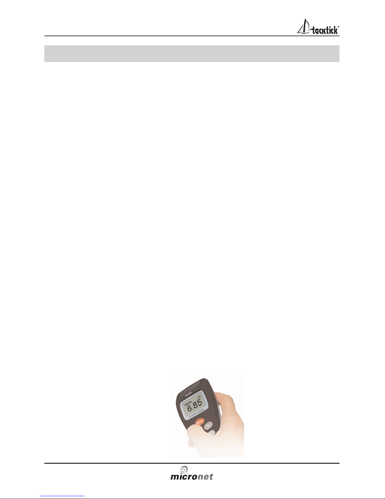
Your Micronet Race Master is the ultimate wind shift indicator, giving you
precise, clear numerical and graphical readouts.
During the race, you can get an instant visual display of:
Your heading as a large stable digital number (the upper display)
How far you are sailing above or below the mean close hauled heading
(lifted or headed) as a precise digital number (the lower display)
How far you are lifted or headed in bar graph format for instant visual
impact (the vertical bar graph)
Micronet Race Master gives you this critical information when you are
sailing both upwind AND downwind. You sail your boat for maximum
speed to windward, using the Micronet Race Master to identify the
headers and lifts to help you decide when to tack. Timing your tacks and
gybes is absolutely critical to winning races and Micronet Race Master
shows you the wind shifts more clearly than ever before.
Racing and Start Line Bias
If the starting line is laid at exactly right angles to the wind, the distance
sailed to the windward mark is the same wherever the boat starts on the
start line.
If the start line is not laid at exactly
ninety degrees to the wind, there is
a favoured end to the line; a boat
that starts at the favoured end
starts upwind and therefore ahead
of a boat starting at the other end
of the line. The angle between the
actual line heading and the
theoretical line at right angles to
the wind is called the Line Bias;
the larger the bias angle, the
greater the advantage to be
gained from starting at the
favoured end of the line.
The diagram (right) shows the relationship between these values.
Optimise your start with the Micronet Race Master
Your Micronet Race Master has the ability to capture the Line
Perpendicular (the heading at right angles to windward of the start line)
and to display the Line Bias angle and the favoured end of the line.

Race Master System
8
3.3 Before the Race
If you have wind data available on the Micronet Network, the required
information is automatically captured by the system (see section 5.7);
otherwise you need to programme the Mean Wind Direction (MWD) and
Tack Angle (TAK) as follows:
To set the Mean Wind Direction (MWD) and Tack Angle (TAK) in
"Single Button" mode
Go to the Wind Shift (WND) page.
Sail upwind for several minutes to determine your average close hauled
heading on each tack.
Press and hold . Rotating lines will appear on the display.
Steer your average close hauled course on either tack.
When the display shows the pop-up "TAC NOW", tack the boat and sail
your close hauled course on the other tack.
The rotating lines will reappear on the display, hold your close hauled
course until the Tack Angle (TAK) pop-up appears.
The displayed value can be adjusted using and .
To capture the Line Perpendicular and the Line Bias
Ensure that the Mean Wind Direction (MWD) has been captured (see the
section above).
Go to the Line Bias (LiNE) page.
Sail directly along the start line, then press .
A pop-up is displayed showing the Line Bias angle and the favoured
end of the start line based on the captured Mean Wind Direction (MWD).
When the pop-up closes, the bottom pane shows the Line Perpendicular
(the bearing at right angles to windward of the the start line).
To check the direction of the Line Bias
If the wind changes prior to the start, provided you have captured the
Line Perpendicular, as described above, you can check the Line Bias at
any time as follows:
Go to the Line Bias (LiNE) page.

Racing Functions
9
Steer the boat towards the eye of the wind until the Heading in the upper
pane matches the Line Perpendicular in the lower pane.
If the wind is coming from the starboard side, the line is starboard
biased. If the wind is coming from the port side, the line is port biased.
To set the Start Timer
Go to the Race Timer (TMR) page.
Press for 1 second, the last start countdown value is shown, flashing.
If required adjust the countdown value using and .
Press to exit edit mode and prepare for countdown.
At the first "gun" press to start the countdown.
The timer will sound a single beep at the end of each minute.
During the last minute, the timer will sound a beep every ten seconds.
During the final ten seconds, the timer will beep every second.
"START" will be indicated by a triple beep.
At the end of the countdown, a pre-selected data page is displayed,
(see page 25 to select the page).
The timer will count the elapsed time in the background, until stopped by
scrolling to the Race Timer (TMR) page and pressing for two seconds.
To adjust the Timer
At any time during the countdown, press to resynchronise the
countdown to the nearest minute.

Race Master System
10
3.4 During the Race
Sailing upwind.
Tack when headed to keep the boat sailing on the lifted tack.
The bar graph indicates the Wind Shift in 2.5 degree steps from a central
zero. Bar Graph above the centre line indicates a lift, Bar Graph below
the centre line indicates a header.
When the Wind Shift (WND) page is selected, Wind Shift is shown as a
+ (lifted) or - (headed) value in the lower pane.
Oscillating wind pattern
If the wind is swinging regularly either side of the Mean Wind
Direction (MWD), you should tack on headers to keep sailing
on the lifted tack, i.e. you should tack on "-" digital or bar graph
indications.
Permanent wind shifts
These can be recognised as a constant header on one tack, and a
constant lift on the other tack. In this situation, you can adjust the
Mean Wind Direction (MWD) as follows:
If you have Wind Data on the Micronet Network:
1. Go to the Wind Shift (WND) page
2. Press , Mean Wind Direction (MWD) is reset to the current
True Wind Direction (TWD).
3. The Mean Wind (MWD) pop-up is displayed.
4. If required, the value may be adjusted using and .
If you do not have wind data on the network:
1. Sail close hauled on either tack.
2. If on starboard tack, press . If on port tack tack, press
The new Mean Wind Direction (MWD) is captured.
3. The Mean Wind Direction (MWD) pop-up is displayed.
4. If required, the value can be adjusted using and .

Sailing Downwind
Gybe to keep the bar graph low, to sail on the headed tack.
The bar graph displays Downwind Angle (the angle of the boat
from the mean downwind direction) in 2.5 degree steps from
0 to 50 degrees, from zero at the bottom of the display. For
example, at 45 degrees the bar graph is almost full length and the boat
is sailing at 45 degrees from the mean downwind direction.
When the Wind Shift (WND) page is selected, Downwind Angle is shown
on the numeric display and the direction is shown by (Port) or (Stbd),
e.g.the example shows that the boat is sailing 20 degrees to starboard
of the mean down wind direction.
Racing Functions
11

Race Master System
12
4 Advanced Racing Functions
The following additional functions are provided to set Mean Wind
Direction (MWD) and Tack Angle (Note: they are not required if wind
data is available on the Micronet network).
To set the Mean Wind Direction (MWD) and Tack Angle(TAK) by
sailing closehauled
1. Go to the Wind Shift (WND) page.
2. Sail upwind for several minutes to determine your average close
hauled heading on each tack.
3. Steer your average close hauled heading on either tack.
4. Press the display will beep twice and "TAC NOW" will show for
two seconds.
5. Tack and sail your average close hauled heading on the new tack.
6. Press again, the display will beep three times and the Tack Angle
(TAK) pop-up will be displayed.
The Tack Angle (TAK) can be adjusted using and .
To set the Mean Wind Direction (MWD) to a known value
If you know the required Mean Wind Direction (MWD), you can set it at
any time as follows (you do not need to be sailing):
1. Go to the Wind Shift (WND) page.
2. Press and hold for 2 seconds, rotating lines are shown.
3. Press , the Mean Wind Direction (MWD) pop-up is displayed.
4. Set the desired heading using and .

To set the Tack Angle (TAK) to a known value
If you know the required Tack Angle (TAK), you can set it at any time as
follows (you do not need to be sailing):
1. Follow the procedure above to display the Mean Wind Direction
(MWD) pop-up.
2. Press , the Tack Angle (TAK) pop-up is displayed.
3. Set the required value using and .
To correct the Mean Wind Direction (MWD) by going head to wind
For Wind Shift to work correctly, you must ensure that the tack angle is
captured using one of the methods described above.
1. Go to the Wind Shift (WND) page.
2. Take the boat head to wind.
3. Press and hold for 2 seconds, rotating lines are shown.
4. Press and hold again for 1 second, the Mean Wind Direction
(MWD) pop-up is displayed.
If necessary, adjust the captured value using and ..
Advanced Racing Functions
13

Race Master System
14
5 Micronet Functions
Information in the bottom pane is displayed in a Chapter and Page
format, each chapter containing one or more pages of related
information.
When Speed, and Depth transducers are connected via the Hull
Transmitter, the following chapters and pages are available:
Wind Shift
Heading
Speed, Maximum Speed, Speed Trim, Distance Travelled, Trip
Distance, Sea Temperature
Depth, Depth Pop-up, Depth Shallow Alarm
Note: Data from additional Micronet transmitters and from connected
NMEA devices can also be displayed on the Micronet Race Master.
The diagram on page 15 shows the full set of data displays that are
available.
For a detailed description of individual data items supported on the
Micronet network, see the Micronet Data user guide on your product CD
or on the Tacktick web site.
5.1 Chapter and Page operation
Use to scroll through the chapters and and to move
between the pages within a chapter.
Pressing at any time moves to the next chapter and the page last
selected in that chapter will be displayed. Both chapter and page
selection will scroll back to the first page once a cycle has been
completed.
When switched on, the Race Master automatically detects the
transmitters connected to the Micronet network and selects Networked
or Standalone mode as appropriate. Pages for which no data is
available on the network are automatically removed from the page
rollover.

Micronet Functions
15
Chapter and Page Diagram

Race Master System
16
5.2 Display Modes
Three display modes can be selected in setup (page 24).
Heading Mode (default)
The top pane of the display always shows the boat's Heading
and the heading page is removed from the bottom pane
rollover.
The bar graph can be configured to show either Wind Shift
(default), Depth or Speed Trim (see below).
Speed Mode
The top pane of the display always shows Boat Speed and the
Boat Speed page is removed from the bottom pane rollover.
The bar graph can be configured to show Speed Trim (default),
Depth or Wind Shift (see below).
Wind Direction Mode
The top pane of the display shows Wind direction.
Apparrent Wind Speed (AWS), Apparrent Wind Angle (AWA),
Beaufort Wind Speed (BFT) and Heading (HDG) are available
in the lower pane. The bar graph is disabled in this mode.
5.3 Depth Pop-up and Depth Shallow Alarm
To warn of shallow water, a depth pop-up and shallow water alarm can
be configured in setup.
Depth Pop-up
When the depth is less than a pre-set value, the Depth page
automatically replaces the data item displayed in the lower
pane. The Depth page continues to be displayed until the
depth increases above the preset level, when the original lower
pane display is restored.
Depth Shallow Alarm
Sounds to indicate that the water depth has fallen below a
preset level. The “bell” icon is displayed in the lower pane.
The depth value that triggers the alarm is affected by any keel
or waterline offsets that have been added. See page 22 to set
the alarm function. The alarm does not sound as the depth increases
above the preset level.
5.4 Speed Trim
To allow visualisation of speed trends, a speed trim function is available
The Speed Trim bargraph shows the percentage difference between the
current boat speed and a reference speed.
The Race Master automatically calculates the reference speed
as the rolling average of the boat speed over the previous two
minutes; this value is shown in the lower pane of the Speed

Trim (TriM) page.
If required, you can use the Speed Trim (TriM) page to lock the reference
speed.
Pressing captures the current boat speed as the reference for the
trim function and the locked value is displayed.
Once locked the reference speed remains fixed until the Race Master is
switched off.
5.5 Bar Graph Functionality
The bar graph can be configured in setup (see page 24) to show one of
the data items described below. Note: in stand alone mode, Wind Shift
is the only bar graph function available.
Wind Shift
Upwind, wind shift is indicated using a fixed scale of +/- 25
degrees about a central zero.
Each segment of the graph corresponds to 2.5 degrees of shift.
Downwind, the graph indicates the angle sailed relative to the
Mean Wind Direction (MWD) from a zero at the bottom of the
graph.
Each segment of the graph corresponds to 2.5 degrees of shift.
Depth
Depth is indicated using a fixed scale 0 to 20m with zero at the
bottom of the graph. Each segment of the graph corresponds to
1m of depth. The bar graph always indicates depth in metres,
even if other depth units are chosen for the digital display.
Speed Trim
Speed trim is indicated using a default scale of +/- 25 percent
about a central zero. The scale can set between +/- 25 and +/1
100 percent in setup (see page 22).
Micronet Functions
17

5.6 Page Hiding
You may hide unwanted pages to configure the Race Master to your
needs:
To select page hiding mode
Press and hold to enter set up
Press repeatedly to reach the OPT (Options) chapter
Press repeatedly to reach the HiDE (Page Hiding) page
Press to activate page hiding for 5 minutes
Press and hold to exit setup.
To hide pages
Once page hiding is activated:
Use and to select a page to hide
Press for 2 seconds to hide the currently visible page.
A period of 5 minutes is allowed during which you may hide pages.
If you have previously hidden pages and wish to return to all
pages visible
Go to the setup OPT (Options) chapter (as above)
Press repeatedly to reach the PAgE HID (Pages Hidden) page
Press to restore all hidden pages
Press and hold to exit setup.
5.7 Operation with Wind Data on the network
When Wind data is available on the network, operation of the Race
Master wind and line bias functions is simplified.
Mean Wind Direction (MWD) is automatically calculated as an
average of the true wind direction. The time period for the average can
be configured in setup (see page 23).
The automatic value can be over-ridden at any time by pressing in
the Wind Shift (WND) page; the current true wind direction is captured
and retained as the Mean Wind Direction (MWD); the MWD popup is
shown to allow editing of the captured value Averaging is then disabled
until the system is switched off.
The manual setup functions for Mean Wind Direction (MWD) and Tack
Angle (TAK) are redundant and are disabled.
Line Bias (LinE) is captured as in section 3.3 (page 8). The Line Bias
page permanently shows the bias angle and preferred end of
the line; which are continually updated to reflect changes in the
wind direction. Line Perpendicular is redundant and is not
displayed.
Race Master System
18
Table of contents