Microtips Technology MT-DEPG0420BNU276F13 User manual

Tel: 1 (888) 499-8477
Fax: (407) 273-0771
E-mail: mtusainfo@microtipsusa.com
Web: www.microtipsusa.com
CUSTOMER
APPROVED BY
DATE:
EPD Module User Manual
This module uses ROHS material
Specification for 4.2 inch EPD
Page 1of 45
Model NO: MT-DEPG0420BNU276F13

EPD Module User Manual
Page 2of45
Revision History
Version
Content
Date
Producer
2.0
New release
2021/08/03

EPD Module User Manual
Page 3of45
CONTENTS
1. Over View..................................................................................................................... 5
2. Features.........................................................................................................................5
3. Mechanical Specification............................................................................................. 6
4.Mechanical Drawing of EPD Module...........................................................................7
5. Input/output Pin Assignment........................................................................................ 8
6. Electrical Characteristics.............................................................................................. 9
9.Typical Application Circuit with SPI Interface...........................................................36
10 Typical Operating Sequence......................................................................................37
10.1 LUT from OTP Operation Flow.........................................................................37
10.2 LUT from OTP Operation Reference Program Code........................................ 38
11. Reliability Test.......................................................................................................... 39
12.Quality Assurance......................................................................................................40
12.1 Environment....................................................................................................... 40
12.2 Illuminance......................................................................................................... 40
12.3 Inspect method....................................................................................................40
12.4 Display area........................................................................................................ 40
6.1 Absolute Maximum Rating.................................................................................... 9
6.2 Panel DC Characteristics......................................................................................10
6.3 Panel AC Characteristics...................................................................................... 11
6.3.1 MCU Interface Selection...............................................................................11
6.3.2 MCU Serial Interface (4-wire SPI)............................................................... 11
6.3.3 MCU Serial Interface (3-wire SPI)............................................................... 12
6.3.4 Interface Timing............................................................................................ 12
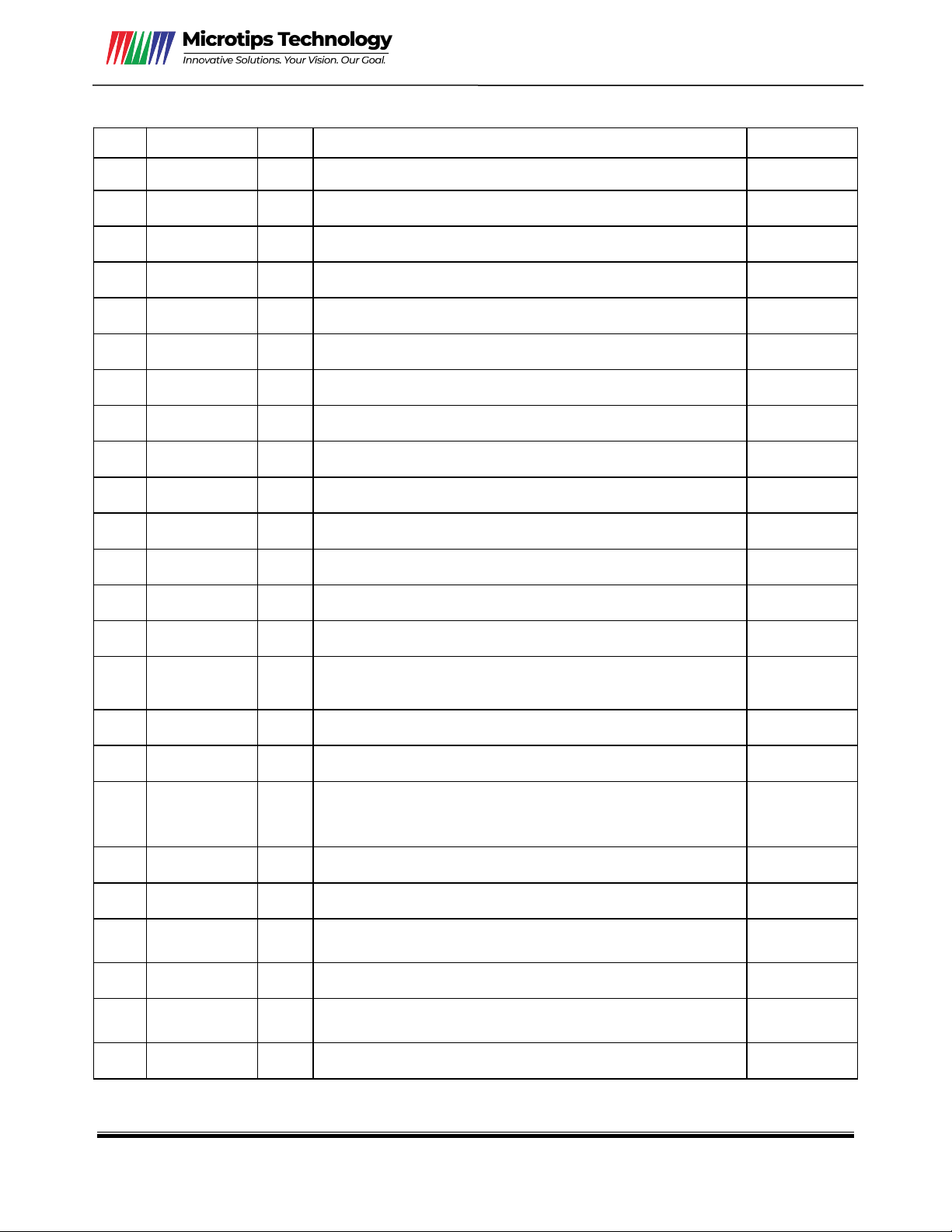
7.Command Table...........................................................................................................14
8. Block Diagram............................................................................................................35

EPD Module User Manual
Page 4of45
12.5 Ghosting test method..........................................................................................40
12.6 Inspection standard.............................................................................................41
12.6.1 Electric inspection standard........................................................................ 41
12.6.2 Appearance inspection standard..................................................................42
13. Packaging..................................................................................................................44
14. Handling, Safety, and Environment Requirements..................................................45

EPD Module User Manual
Page 5of45
1. Over View
MT-DEPG0420BNU276F13 is an Active Matrix Electrophoretic Display (AM EPD), with
interface and a reference system design. The display is capable to display images at 1-bit white and
black full display capabilities. The 4.2 inch active area contains 300×400 pixels. The module is a
TFT-array driving electrophoresis display, with integrated circuits including gate driver, source
driver, MCU interface, timing controller, oscillator, DC-DC, SRAM, LUT, VCOM. Module can be
used in portable electronic devices, such as Electronic Shelf Label (ESL) System.
2. Features
◆300×400 pixels display
◆High contrast High reflectance
◆Ultra wide viewing angle Ultra low power consumption
◆Pure reflective mode
◆Bi-stable display
◆Commercial temperature range
◆Landscape portrait modes
◆Hard-coat antiglare display surface
◆Ultra Low current deep sleep mode
◆On chip display RAM
◆Waveform can stored in On-chip OTP or written by MCU
◆Serial peripheral interface available
◆On-chip oscillator
◆On-chip booster and regulator control for generating VCOM, Gate and Source driving
voltage
◆I2C signal master interface to read external temperature sensor
◆Built-in temperature sensor

EPD Module User Manual
Page 6of45
3. Mechanical Specification
Parameter
Specifications
Unit
Remark
Screen Size
4.2
Inch
Display Resolution
400(H)×300(V)
Pixel
DPI:120
Active Area
84.8×63.6
mm
Pixel Pitch
0.212×0.212
mm
Pixel Configuration
Rectangle
Outline Dimension
91 (H)×77 (V) ×1.2(D)
mm
Weight
16.1±0.3
g
Symbol
Parameter
Conditions
Min
Typ.
Max
Units
Notes
KS
Black State L* value
-
18
20
3-1
Black Ghosting ΔL
-
1
-
3-1
WS
White State L* value
66
67
-
3-1
White Ghosting ΔL
-
1
-
3-1
R
White Reflectivity
White
30
34
-
%
3-1
CR
Contrast Ratio
Indoor
15:1
20:1
-
3-1
3-2
GN
2Grey Level
-
-
-
-
Life
Temp:23±3°C
Humidity:55±10%RH
5years
3-3
Notes: 3-1. Luminance meter: Eye-One Pro Spectrophotometer.
3-2. CR=Surface Reflectance with all white pixel/Surface Reflectance with all black pixels.
3-3. When the product is stored. The display screen should be kept white and face up.

EPD Module User Manual
Page 7of45
4.Mechanical Drawing of EPD Module
Confirmation: DATE REV. MODIFICATION
1 DISPLAY MODULE 4.2" ARRAY FOR EPD
2 DRIVER IC:UC8276C
NOTE
3 RESOLUTION:300gateX400source
4 PIXEL SIZE:0.212mmX0.212mm
.XXX=±0.20mm
.XX=±0.20mm
.X=±0.4mm
ANGLES±5°
SY ZHAO
CC ZHENG
RoHS
mm 1/1
DEPG0420_ _U276F13EPD A 19.11.28
XZ FAN

EPD Module User Manual
Page 8of45
5. Input/output Pin Assignment
No.
Name
I/O
Description
Remark
1
NC
Do not connect with other NC pins
Keep Open
2
GDR
O
N-Channel MOSFET Gate Drive Control
3
RESE
I
Current Sense Input for the Control Loop
4
NC
NC
Do not connect with other NC pins
Keep Open
5
VSH2
C
Positive Source driving voltage 2
6
TSCL
O
I2C Interface to digital temperature sensor Clock pin
7
TSDA
I/O
I2C Interface to digital temperature sensor Data pin
8
BS1
I
Bus Interface selection pin
Note 5-5
9
BUSY
O
Busy state output pin
Note 5-4
10
RES#
I
Reset signal input. Active Low.
Note 5-3
11
D/C#
I
Data /Command control pin
Note 5-2
12
CS#
I
Chip select input pin
Note 5-1
13
SCL
I
Serial Clock pin (SPI)
14
SDA
I/O
Serial Data pin (SPI)
15
VDDIO
P
Power Supply for interface logic pins It should be
connected with VCI
16
VCI
P
Power Supply for the chip
17
VSS
P
Ground
18
VDD
C
Core logic power pin VDD can be regulated internally
from VCI. A capacitor should be connected between
VDD and VSS
19
VPP
P
FOR TEST
Keep Open
20
VSH1
C
Positive Source driving voltage
21
VGH
C
Power Supply pin for Positive Gate driving voltage and
VSH1
22
VSL
C
Negative Source driving voltage
23
VGL
C
Power Supply pin for Negative Gate driving voltage
VCOM and VSL
24
VCOM
C
VCOM driving voltage
I = Input Pin, O =Output Pin, I/O = Bi-directional Pin (Input/Output), P = Power Pin, C = Capacitor Pin

EPD Module User Manual
Page 9of45
Note 5-1: This pin (CS#) is the chip select input connecting to the MCU. The chip is enabled for MCU
communication only when CS# is pulled LOW.
Note 5-2: This pin is (D/C#) Data/Command control pin connecting to the MCU in 4-wire SPI mode. When
the pin is pulled HIGH, the data at SDA will be interpreted as data. When the pin is pulled LOW,
the data at SDA will be interpreted as command.
Note 5-3: This pin (RES#) is reset signal input. The Reset is active low.
Note 5-4: This pin is Busy state output pin. When Busy is Low, the operation of chip should not be
interrupted, command should not be sent. The chip would put Busy pin Low when -Outputting
display waveform -Communicating with digital temperature sensor
Note 5-5: Bus interface selection pin
BS1 State
MCU Interface
L
4-lines serial peripheral interface(SPI) - 8 bits SPI
H
3- lines serial peripheral interface(SPI) - 9 bits SPI
6. Electrical Characteristics
6.1 Absolute Maximum Rating
Parameter
Symbol
Rating
Unit
Logic supply voltage
VCI
-0.3 to +6.0
V
Logic Input voltage
VIN
-0.3 to VCI +0.3
V
Operating Temp range
TOPR
0 to +50
ºC.
Storage Temp range
TSTG
-25 to+70
ºC.
Optimal Storage Temp
TSTGo
23±3
ºC.
Optimal Storage Humidity
HSTGo
55±10
%RH
Note: Maximum ratings are those values beyond which damages to the device may occur. Functional
operation should be restricted to the limits in the Panel DC Characteristics tables.

EPD Module User Manual
Page 10of45
6.2 Panel DC Characteristics
The following specifications apply for: VSS=0V, VCI=3.0V, TOPR =25ºC.
Parameter
Symbol
Condition
Applicab
le pin
Min.
Typ.
Max.
Unit
Single ground
VSS
-
-
0
-
V
Logic supply voltage
VCI
-
VCI
2.3
3.0
3.6
V
Core logic voltage
VDD
VDD
2.3
3.0
3.6
V
High level input voltage
VIH
-
-
0.7 VCI
-
VCI
V
Low level input voltage
VIL
-
-
0
-
0.3 VCI
V
High level output voltage
VOH
IOH =400uA
-
VCI -0.4
-
-
V
Low level output voltage
VOL
IOL = -400uA
-
0
-
0.4
V
Typical power
PTYP
VCI =3.0V
-
-
12.6
-
mW
Deep sleep mode
PSTPY
VCI =3.0V
-
-
0.003
-
mW
Typical operating current
Iopr_VCI
VCI =3.0V
-
-
4.2
-
-
mA
Image update time
-
25 ºC
-
-
4
-
sec
Typical peak current
Iopr_VCI
2.3~3.6V
50
60
mA
Sleep mode current
Islp_VCI
DC/DC off
No clock
No input load
Ram data retain
-
-
20
uA
Deep sleep mode current
Idslp_VCI
DC/DC off
No clock
No input load
Ram data not retain
-
-
1
5
uA
Notes: 1. The typical power is measured with following transition from horizontal 2 scale pattern to vertical
2 scale pattern.
2. The deep sleep power is the consumed power when the panel controller is in deep sleep mode.
3. The listed electrical characteristics are only guaranteed under the controller & waveform provided
by MT.
4. Electrical measurement:Tektronix oscilloscope - MDO3024,
Tektronix current probe–TCP0030A.

EPD Module User Manual
Page 11of45
6.3 Panel AC Characteristics
6.3.1 MCU Interface Selection
The pin assignment at different interface mode is summarized in Table 6-3-1. Different MCU
mode can be set by hardware selection on BS1 pins. The display panel only supports 4-wire SPI or
3-wire SPI interface mode.
Pin Name
Data/Command Interface
Control Signal
Bus interface
SDA
SCL
CS#
D/C#
RES#
BS1=L 4-wire SPI
SDA
SCL
CS#
D/C#
RES#
BS1=H 3-wire SPI
SDA
SCL
CS#
L
RES#
Table 6-3-1: MCU interface assignment under different bus interface mode
6.3.2 MCU Serial Interface (4-wire SPI)
The serial interface consists of serial clock SCL, serial data SDA, D/C#, CS#. This interface
supports Write mode and Read mode.
Table 6-3-2: Control pins of 4-wire Serial Peripheral interface
Note: ↑ stands for rising edge of signal
Figure 6-3-1: 4-wire SPI mode
Function
CS#
D/C#
SCL
Write command
L
L
↑
Write data
L
H
↑

EPD Module User Manual
Page 12of45
6.3.3 MCU Serial Interface (3-wire SPI)
Function
CS#
D/C#
SCL
Write command
L
Tie
↑
Write data
L
Tie
↑
Table 6-3-3: Control pins of 4-wire Serial Peripheral interface
Note:↑ stands for rising edge of signal
Figure 6-3-2: 3-wire SPI mode
6.3.4 Interface Timing

EPD Module User Manual
Page 13of45
Serial Interface Timing Characteristics
Symbol
Signal /Parameter
Conditions
Min.
Typ.
Max.
Unit
TCSS
CSB
Chip select setup time
60
ns
TCSH
Chip select hold time
65
ns
TSCC
Chip select setup time
20
ns
TCHW
Chip select setup time
40
ns
TSCYCW
SCL
Serial clock cycle(Write)
100
ns
TSHW
SCL “H” pulse width(Write)
35
ns
TSLW
SCL “L” pulse width(Write)
35
ns
TSCYCR
Serial clock cycle(Read)
150
ns
TSHR
SCL “H” pulse width(Read)
60
ns
TSLR
SCL “L” pulse width(Read)
60
ns
TDCS
DC
DC setup time
30
ns
TDCH
DC hold time
30
ns
TSDS
SDA
(DIN)
Data setup time
30
ns
TSDH
Data hold time
30
ns
TACC
SDA
(DOUT)
Access time
150
ns
TOH
Output disable time
15
ns

EPD Module User Manual
Page 14of45
7.Command Table
W/R: 0: Write Cycle / 1: Read Cycle C/D: 0: Command / 1: Data D7-D0: –: Don’t Care
1) PANEL SETTING(PSR) (REGISTER:R00H)
Action
W/R
C/D
D7
D6
D5
D4
D3
D2
D1
D0
Setting the panel
0
0
0
0
0
0
0
0
0
0
0
1
RES1
RES0
REG
KW/R
UD
SHL
SHD_N
RST_N
0
1
-
-
-
VCMZ
TS_AUTO
TIEG
NORG
VC_LUTZ
RES[1:0]: Display Resolution setting(source x gate)
00b: 400x300 (Default) Active source channels: S0 ~ S399. Active gate channels: G0~G299..
01b:320x300 Active source channels: S0 ~ S319. Active gate channels: G0~G299.
10b:320x240 Active source channels: S0 ~ S319. Active gate channels: G0~G239..
11b:200x300 Active source channels: S0 ~ S199. Active gate channels: G0~G299.
REG: LUT selection
0: LUT from OTP.(Default)
1: LUT from register.
BWR: Black / White / Red
0: Pixel with Black/White/Red, KWR mode. (Default)
1: Pixel with Black/White, KW mode.
UD: Gate Scan Direction
0: Scan down. First line to Last line:Gn-1→ Gn-2→ Gn-3→ …→ G0
1: Scan up.(Default) First line to Last line:G0→ G1→ G2→ …….→ Gn-1
SHL: Source Shift Direction
0: Shift left. First data to Last data:Sn-1→ Sn-2→ Sn-3→ …→ S0
1: Shift right.(Default) First data to Last data:S0→ S1→ S2→ …….→ Sn-1
SHD_N: Booster Switch
0: Booster OFF
1: Booster ON (Default)
When SHD_N becomes LOW, charge pump will be turned OFF, register and SRAM
data will keep until VDD OFF. And Source/Gate/Border/VCOM will be released to
floating.
RST_N: Soft Reset
0: Reset. Booster OFF, Register data are set to their default values, all
drivers will be reset, and all functions will be disabled.
Source/Gate/Border/VCOM will be released to floating. After soft reset
is transmitted, the internal operation needs at least 50uS to execute.
During this period of time, the BUSY_N pin keeps low and any
command will be ignored.1: No effect (Default).
1: No effect (Default).

EPD Module User Manual
Page 15of45
VCMZ: VCOM function
0: No effect (Default).
1: VCOM is always floating.
TS_AUTO: Temperature sensor will be activated automatically one time.
0: No effect (Default).
1: Before enabling booster.Temperature sensor will be activated automatically one time.
TIEG: VGL state function
0: No effect (Default)
1 : After power off booster, VGL will be tied to GND.
NORG: VCOM state during refreshing display
0: No effect (Default)
1: Expect refreshing display, VCOM is tied to GND.
VC_LUTZ: VCOM state during refreshing display
0: No effect (Default)
1: After refreshing display, the output of VCOM is set to floating
automatically.
Note: Priority of Vcom setting: VCMZ > EOPT > NORG > VC_LUTZ

EPD Module User Manual
Page 16of45
2)POWER SETTING(PWR) (R01H)
BD_EN: Border l do enable control
0: Border LDO disable(Default)
Border level selection:00b:VCOM 01b:VSH 10b:VSL 11b:VDHR
1: Border LDO enable
Border level selection:00b:VCOM 01b:VBH(VCOM-VSL)10b:VSL 11b:VDHR
VDS_EN: Source power selection
0 : External source power from VDH/VDL/VDHR pins
1 : Internal DC/DC function for generating VDH/VDL/VDHR(Default)
VDG_EN: Gate power selection
0 : External gate power from VGH/VGL pins
1 : Internal DC/DC function for generating VGH/VGL(Default)
VCOM_HV: VCOM Voltage Level
0: VCOMH=VSH+VCOM_DC, VCOML=VSL+VCOM_DC.(Default)
1: VCOMH=VGH, VCOML=VGL
VGHL_LV[1:0]: VGH / VGL Voltage Level selection.
VSH[5:0]: Internal VSH power selection for B/W pixel.(Default value: 11 1111b)
VSH
Voltage
VSH
Voltage
VSH
Voltage
VSH
Voltage
000000
2.4V
010000
5.6V
100000
8.8V
110000
12.0V
000001
2.6V
010001
5.8V
100001
9.0V
110001
12.2V
000010
2.8V
010010
6.0V
100010
9.2V
110010
12.4V
000011
3.0V
010011
6.2V
100011
9.4V
110011
12.6V
000100
3.2V
010100
6.4V
100100
9.6V
110100
12.8V
000101
3.4V
010101
6.6V
100101
9.8V
110101
13.0V
VGHL_LV
VGHL Voltage Level
0000(Default)
VGH=20V, VGL=-20V
0001
VGH=19V, VGL=-19V
0010
VGH=18V, VGL=-18V
0011
VGH=17V, VGL=-17V
0100
VGH=16V, VGL=-16V
0101
VGH=15V, VGL=-15V
0110
VGH=14V, VGL=-14V
0111
VGH=13V, VGL=-13V
1000
VGH=12V, VGL=-12V
1001
VGH=11V, VGL=-11V
1010
VGH=10V, VGL=-10V
Action
W/R
C/D
D7
D6
D5
D4
D3
D2
D1
D0
Selecting Internal
/External Power
0
0
0
0
0
0
0
0
0
1
0
1
-
-
-
BD_EN
-
-
VDS_E
N EN
VDG_EN
0
1
-
-
-
VCOM_SLEW
VGHL_LV[3:0]
0
1
-
-
VSH[5:0]
0
1
-
-
VSL[5:0]
0
1
OPTEN
VDHR[6:0]

EPD Module User Manual
Page 17of45
000110
3.6V
010110
6.8V
100110
10.0V
110110
13.2V
000111
3.8V
010111
7.0V
100111
10.2V
110111
13.4V
001000
4.4V
011000
7.2V
101000
10.4V
111000
13.6V
001001
4.2V
011001
7.4V
101001
10.6V
111001
13.8V
001010
4.4V
011010
7.6V
101010
10.8V
111010
14.0V
001011
4.6V
011011
7.8V
101011
11.0V
111011
14.2V
001100
4.8V
011100
8.0V
101100
11.2V
111100
14.4V
001101
5.0V
011101
8.2V
101101
11.4V
111101
14.6V
001110
5.2V
011110
8.4V
101110
11.6V
111110
14.8V
001111
5.4V
011111
8.6V
101111
11.8V
111111
15.0V
VSL[5:0]: Internal VSL power selection for B/W pixel. (Default value: 11 1111b)
VSL
Voltage
VSL
Voltage
VSL
Voltage
VSL
Voltage
000000
-2.4V
010000
-5.6V
100000
-8.8V
110000
-12.0V
000001
-2.6V
010001
-5.8V
100001
-9.0V
110001
-12.2V
000010
-2.8V
010010
-6.0V
100010
-9.2V
110010
-12.4V
000011
-3.0V
010011
-6.2V
100011
-9.4V
110011
-12.6V
000100
-3.2V
010100
-6.4V
100100
-9.6V
110100
-12.8V
000101
-3.4V
010101
-6.6V
100101
-9.8V
110101
-13.0V
000110
-3.6V
010110
-6.8V
100110
-10.0V
110110
-13.2V
000111
-3.8V
010111
-7.0V
100111
-10.2V
110111
-13.4V
001000
-4.4V
011000
-7.2V
101000
-10.4V
111000
-13.6V
001001
-4.2V
011001
-7.4V
101001
-10.6V
111001
-13.8V
001010
-4.4V
011010
-7.6V
101010
-10.8V
111010
-14.0V
001011
-4.6V
011011
-7.8V
101011
-11.0V
111011
-14.2V
001100
-4.8V
011100
-8.0V
101100
-11.2V
111100
-14.4V
001101
-5.0V
011101
-8.2V
101101
-11.4V
111101
-14.6V
001110
-5.2V
011110
-8.4V
101110
-11.6V
111110
-14.8V
001111
-5.4V
011111
-8.6V
101111
-11.8V
111111
-15.0V
VDHR[5:0]: Internal VDHR power selection for Red pixel. (Default value: 001101b)
VDHR
Voltage
VDHR
Voltage
VDHR
Voltage
VDHR
Voltage
000000
2.4V
010000
5.6V
100000
8.8V
110000
12.0V
000001
2.6V
010001
5.8V
100001
9.0V
110001
12.2V
000010
2.8V
010010
6.0V
100010
9.2V
110010
12.4V
000011
3.0V
010011
6.2V
100011
9.4V
110011
12.6V
000100
3.2V
010100
6.4V
100100
9.6V
110100
12.8V
000101
3.4V
010101
6.6V
100101
9.8V
110101
13.0V
000110
3.6V
010110
6.8V
100110
10.0V
110110
13.2V
000111
3.8V
010111
7.0V
100111
10.2V
110111
13.4V
001000
4.4V
011000
7.2V
101000
10.4V
111000
13.6V
001001
4.2V
011001
7.4V
101001
10.6V
111001
13.8V
001010
4.4V
011010
7.6V
101010
10.8V
111010
14.0V
001011
4.6V
011011
7.8V
101011
11.0V
111011
14.2V
001100
4.8V
011100
8.0V
101100
11.2V
111100
14.4V
001101
5.0V
011101
8.2V
101101
11.4V
111101
14.6V
001110
5.2V
011110
8.4V
101110
11.6V
111110
14.8V
001111
5.4V
011111
8.6V
101111
11.8V
111111
15.0V

EPD Module User Manual
Page 18of45
OPTEN: 1 enable step-0.1V voltage selection.
VDHR
Voltage
VDHR
Voltage
VDHR
Voltage
VDHR
Voltage
1000 0000
2.4 V
1010 0000
5.6 V
1100 0000
8.8 V
1110 0000
12 V
1000 0001
2.5 V
1010 0001
5.7 V
1100 0001
8.9 V
1110 0001
12.1 V
1000 0010
2.6 V
1010 0010
5.8 V
1100 0010
9.0 V
1110 0010
12.2 V
1000 0011
2.7 V
1010 0011
5.9 V
1100 0011
9.1 V
1110 0011
12.3 V
1000 0100
2.8 V
1010 0100
6.0 V
1100 0100
9.2 V
1110 0100
12.4 V
1000 0101
2.9 V
1010 0101
6.1 V
1100 0101
9.3 V
1110 0101
12.5 V
1000 0110
3.0 V
1010 0110
6.2 V
1100 0110
9.4 V
1110 0110
12.6 V
1000 0111
3.1 V
1010 0111
6.3 V
1100 0111
9.5 V
1110 0111
12.7 V
1000 1000
3.2 V
1010 1000
6.4 V
1100 1000
9.6 V
1110 1000
12.8 V
1000 1001
3.3 V
10101001
6.5 V
1100 1001
9.7 V
1110 1001
12.9 V
1000 1010
3.4 V
1010 1010
6.6 V
1100 1010
9.8 V
1110 1010
13.0 V
1000 1011
3.5 V
1010 1011
6.7 V
1100 1011
9.9 V
1110 1011
13.1 V
1000 1100
3.6 V
1010 1100
6.8 V
1100 1100
10.0 V
1110 1100
13.2 V
1000 1101
3.7 V
1010 1101
6.9 V
1100 1101
10.1 V
1110 1101
13.3 V
1000 1110
3.8 V
1010 1110
7.0 V
1100 1110
10.2 V
1110 1110
13.4 V
1000 1111
3.9 V
1010 1111
7.1 V
1100 1111
10.3 V
1110 1111
13.5 V
1001 0000
4.0 V
1011 0000
7.2 V
1101 0000
10.4 V
1111 0000
13.6 V
1001 0001
4.1 V
1011 0001
7.3 V
1101 0001
10.5 V
1111 0001
13.7 V
1001 0010
4.2 V
1011 0010
7.4 V
1101 0010
10.6 V
1111 0010
13.8 V
1001 0011
4.3 V
1011 0011
7.5 V
1101 0011
10.7 V
1111 0011
13.9 V
1001 0100
4.4 V
1011 0100
7.6 V
1101 0100
10.8 V
1111 0100
14.0 V
1001 0101
4.5 V
1011 0101
7.7 V
1101 0101
10.9 V
1111 0101
14.1 V
1001 0110
4.6 V
1011 0110
7.8 V
1101 0110
11.0 V
1111 0110
14.2 V
1001 0111
4.7 V
1011 0111
7.9 V
1101 0111
11.1 V
1111 0111
14.3 V
1001 1000
4.8 V
1011 1000
8.0 V
1101 1000
11.2 V
1111 1000
14.4 V
1001 1001
4.9 V
1011 1001
8.1 V
1101 1001
11.3 V
1111 1001
14.5 V
1001 1010
5.0 V
1011 1010
8.2 V
1101 1010
11.4 V
1111 1010
14.6 V
1001 1011
5.1 V
1011 1011
8.3 V
1101 1011
11.5 V
1111 1011
14.7 V
1001 1100
5.2 V
1011 1100
8.4 V
11011100
11.6 V
1111 1100
14.8 V
1001 1101
5.3 V
1011 1101
8.5 V
1101 1101
11.7 V
1111 1101
14.9 V
1001 1110
5.4 V
1011 1110
8.6 V
1101 1110
11.8 V
1111 1110
15.0 V
1001 1111
5.5 V
1011 1111
8.7 V
1101 1111
11.9 V
3)POWER OFF(POF) (R02H)
Action
W/R
C/D
D7
D6
D5
D4
D3
D2
D1
D0
Turning OFF the power
0
0
0
0
0
0
0
0
1
0
After the Power OFF command, the driver will be powered OFF. Refer to the POWER
MANAGEMENT section for the sequence.
This command will turn off booster, controller, source driver, gate driver, VCOM, and temperature
sensor, but register data will be kept until VDD turned OFF or Deep Sleep Mode.
Source/Gate/Border/VCOM will be released to floating

EPD Module User Manual
Page 19of45
4)POWER OFF SEQUENCE SETTING(PFS) (R03H)
Action
W/R
C/D
D7
D6
D5
D4
D3
D2
D1
D0
Setting Power OFF sequence
0
0
0
0
0
0
0
0
1
1
0
1
-
-
T_VDS_OFF[1:0]
-
-
-
-
T_VDS_OFF[1:0]: Source to gate power off interval time.
00b: 1 frame(Default) 01b: 2frames 10b: 3frames 11b: 4frame
5)POWER ON(PON) (R04H)
Action
W/R
C/D
D7
D6
D5
D4
D3
D2
D1
D0
Turning ON the power
0
0
0
0
0
0
0
1
0
0
After the Power ON command, the driver will be powered ON. Refer to the POWER
MANAGEMENT section for the sequence.
This command will turn on booster, controller, regulators, and temperature sensor will be activated
for one-time sensing before enabling booster. When all voltages are ready, the BUSY_N signal will
return to high.
6)POWER ON MEASURE(PMES) (R05H)
Action
W/R
C/D
D7
D6
D5
D4
D3
D2
D1
D0
0
0
0
0
0
0
0
1
0
1
This command enables the internal bandgap, which will be cleared by the next POF.
7)BOOSTER SOFT START(BTST) (R06H)
Action
W/R
C/D
D7
D6
D5
D4
D3
D2
D1
D0
Starting data transmission
0
0
0
0
0
0
0
1
1
0
0
1
BT_PHA7
BT_PHA6
BT_PHA5
BT_PHA4
BT_PHA3
BT_PHA2
BT_PHA1
BT_PHA0
0
1
BT_PHB7
BT_PHB6
BT_PHB5
BT_PHB4
BT_PHB3
BT_PHB2
BT_PHB1
BT_PHB0
0
1
-
-
BT_PHC5
BT_PHC4
BT_PHC3
BT_PHC2
BT_PHC1
BT_PHC0
BTPHA[7:6]: Soft start period of phase A.
00b:10mS 01b:20mS 10b:30mS 11b:40mS
BTPHA[5:3]: Driving strength of phase A
000b: strength1
001b: strength2
010b: strength3
011b: strength4
100b: strength5
101b: strength6
110b: strength7
111b: strength 8(strongest)
BTPHA[2:0]: Minimum OFF time setting of GDR in phase A
000b:0.27uS
001b:0.34uS
010b:0.40uS
011b:0.54uS

EPD Module User Manual
Page 20of45
100b:0.80uS
101b:1.54uS
110b:3.34uS
111b:6.58uS
BTPHB[7:6]: Soft start period of phase B
00b:10mS 01b:20mS 10b:30mS 11b:40mS
BTPHB[5:3]: Driving strength of phase B
000b: strength1
001b: strength2
010b: strength3
011b: strength4
100b: strength5
101b: strength6
110b: strength7
111b: strength 8 (strongest)
BTPHB[2:0]: Minimum OFF time setting of GDR in phase B
000b:0.27uS
001b:0.34uS
010b:0.40uS
011b:0.54uS
100b:0.80uS
101b:1.54uS
110b:3.34uS
111b:6.58uS
BTPHC[5:3]: Driving strength of phase C
000b: strength1
001b: strength2
010b: strength3
011b: strength4
100b: strength5
101b: strength6
110b: strength7
111b: strength 8 (strongest)
BTPHC[2:0]: Minimum OFF time setting of GDR in phase C
000b:0.27uS
001b:0.34uS
010b:0.40uS
011b:0.54uS
100b:0.80uS
101b:1.54uS
110b:3.34uS
111b:6.58uS
8)DEEP SLEEP(DSLP) (R07H)
Action
W/R
C/D
D7
D6
D5
D4
D3
D2
D1
D0
Deep Sleep
0
0
0
0
0
0
0
1
1
1
0
1
1
0
1
0
0
1
0
1
After this command is transmitted, the chip will enter Deep Sleep Mode to save power. Deep Sleep
Mode will return to Standby Mode by hardware reset. The only one parameter is a check code, the
command will be executed if check code = 0xA5.
9)DATA START TRANSMISSION 1(DTM1) (R10H)
Action
W/R
C/D
D7
D6
D5
D4
D3
D2
D1
D0
Starting data transmission
0
0
0
0
0
1
0
0
0
0
0
1
Pixel1
Pixel2
Pixel3
Pixel4
Pixel5
Pixel6
Pixel7
Pixel8
0
1
:
:
:
:
:
:
:
:
0
1
Pixel(n-7
)
Pixel(n-6
)
Pixel(n-5
)
Pixel(n-4
)
Pixel(n-3
)
Pixel(n-2
)
Pixel(n-1
)
Pixel(n)
This command starts transmitting data and write them into SRAM.
In KW mode, this command writes “OLD”data to SRAM.
In KWR mode, this command writes “B/W”data to SRAM.
In Program mode, this command writes “OTP”data to SRAM for programming.
Table of contents