Installer Manual Microvideo srl www.microvideo.eu
3
Table of Contents
Warranty.................................................................................................................................................... 5
Limitation of Liability.................................................................................................................................. 5
Copyright................................................................................................................................................... 5
CHAPTER 1 - Introduction................................................................................................................................ 6
Chapter 2 –Modules Description ....................................................................................................................... 7
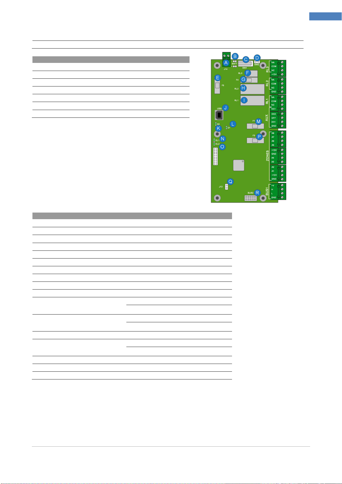
Control Panel................................................................................................................................................. 7
Keyboard (Mod. SY820)................................................................................................................................ 9
LED.............................................................................................................................................................. 10
DISPLAY...................................................................................................................................................... 10
DIRECTIONAL KEYS.................................................................................................................................. 10
INTEGRATED PROXIMITY READER......................................................................................................... 10
NUMERIC KEYPAD .................................................................................................................................... 10
DELETE BUTTON........................................................................................................................................11
ESC KEY......................................................................................................................................................11
MACRO FUNCTION KEYS..........................................................................................................................11
GSM / GPRS Module (Mod. SY860)............................................................................................................11
Expansion Module (Mod. SY840) ............................................................................................................... 12
Inserter Jack Module (Mod. SY825)............................................................................................................ 13
Wall Inserter Module (Mod. SY826) ............................................................................................................ 13
LAN Module (Mod. SY881) ......................................................................................................................... 14
BUS Splitter (Mod. SY930)......................................................................................................................... 14
DVR WALL 4N-8N....................................................................................................................................... 15
Radio Receiver Module (mod. SY910)........................................................................................................ 16
Radio Magnetic Contact Module (mod. SY920)......................................................................................... 16
MAGNET + NC Configuration................................................................................................................. 17
NC + NC Configuration........................................................................................................................... 17
Configuration Magnet + Blinds................................................................................................................ 18
Supervision Function .............................................................................................................................. 18
Report Open/Close Magnet/NC.............................................................................................................. 18
Inertial Radio Module (mod. SY921)....................................................................................................... 18
Supervision Function .............................................................................................................................. 19
Motion Sensor Module (mod. SY925)......................................................................................................... 20
Radio Remote Control (mod. SY915) ......................................................................................................... 21
Procedure for Inserting Through Key...................................................................................................... 22
CHAPTER 3 – Installing ................................................................................................................................. 23
Installing Control Panel ............................................................................................................................... 23
Connection of Voice Module (Mod. SY-900)........................................................................................... 23
Connecting siren to an output................................................................................................................. 24
Sample connection of open collector outputs......................................................................................... 24
Connecting Sensor Alarm to Zones........................................................................................................ 25
Modules Installing on CAN BUS.................................................................................................................. 28
Keyboard Module SY920 Installation.......................................................................................................... 28
Installing the Expansion Module SY840-SY841-SY845 ............................................................................ 29
Installing GSM/GPRS SY860-SY861 Module............................................................................................ 30
Installing LAN SY880-SY881 module ......................................................................................................... 31
Wall Installing of inserter SY826Module...................................................................................................... 32
Installing the SY825 inserter Jack Module.................................................................................................. 33
Installing the SY930 Bus Isolator / Repeater Module ................................................................................. 33
Installing Radio SY920-SY921 Modules ..................................................................................................... 35
Installing SY925 Motion Sensor Module..................................................................................................... 36
Configuring Module Address....................................................................................................................... 37
Addressing Module Keyboards........................................................................................................... 37
Addressing Expansion Module........................................................................................................... 38
Addressing GSM / GPRS Module ...................................................................................................... 38
Testing System............................................................................................................................................ 39
CHAPTER 4– Programming Control Panel..................................................................................................... 40
Installer Menu.............................................................................................................................................. 40
General Parameters................................................................................................................................ 40
ZONES.................................................................................................................................................... 42
RADIO ZONES ....................................................................................................................................... 43