manuals.online logo
Brands
  1. Home
  2. •
  3. Brands
  4. •
  5. MITECH
  6. •
  7. Security System
  8. •
  9. MITECH FOSTER POWER User manual

MITECH FOSTER POWER User manual

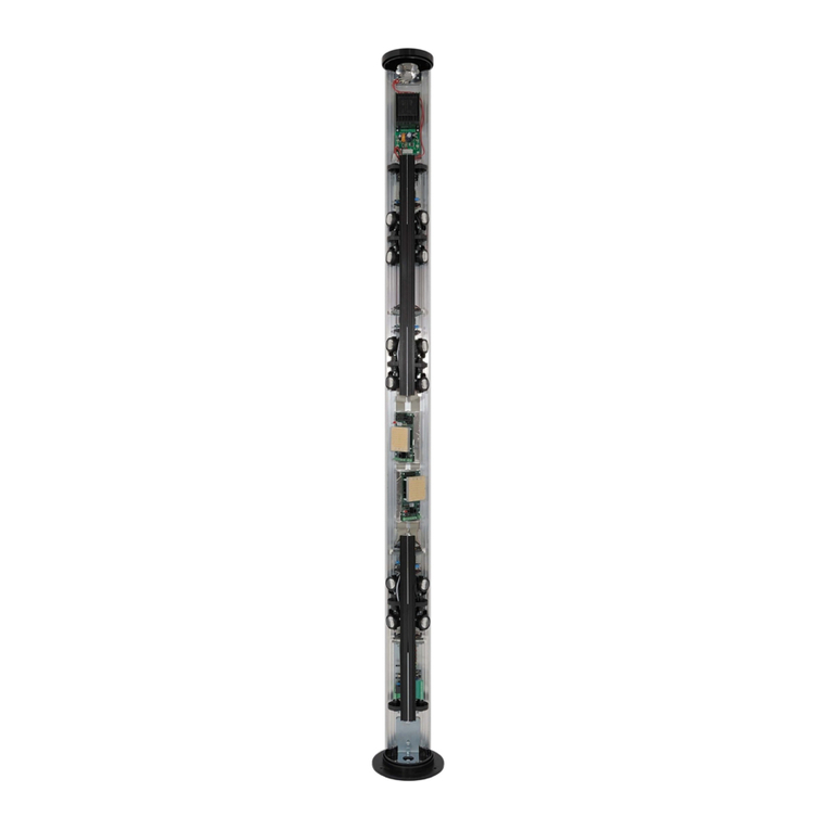
FOSTER POWER
ACTIVE INFRARED BARRIER
WITH INTEGRATED POWER SUPPLY
Installation and user manual
MADE IN ITALY
FOSTER POWER Installation and user manual Page 2 of 20
Index
Introduction
and warnings
Page 3
Components and accessories
Page 4
General
installation instructions
Page 5
Bracket
mounting options
Page 5
Examples
of installation
Page 6
•
Pole mounting with bracket FTN SUP …………………………………………………...................................... 5
•
Wall mounting with bracket FTN WL ……………………………………………………………………………………… 5
Receiver
and transmitter motherboards Page
8
Power
supply
Page 10
Alignment
Page 11
Settings
and programming
Page 13
•
Description of signalling leds ……………………………………………………………………………………………….. 14
•
Description of jumper settings ………………………………………………………………………………………………15
Technical
features and consumption
Page 16
Notes
Page 17
•
Receiver (RX) …………………………………………………………..…………………………………………………………… 8
•
Transmitter (TX) ……………………….………….….…………………………………………………………………………… 9
FOSTER POWER Installation and user manual Page 3 of 20
Introduction
and warnings
INTRODUCTION
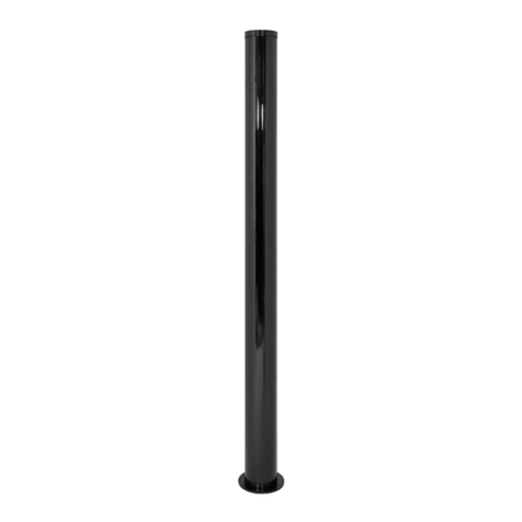
FOSTER POWER is a perimeter IR barrier with crossed
beams for protection of external areas, with a pleasant
design and compact dimensions.
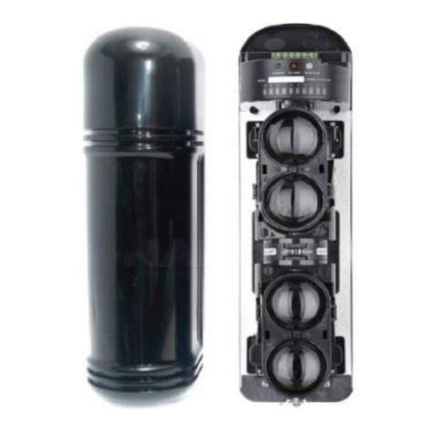
Pre-cabled and ready for installation FOSTER POWER is
composed of a transmitting and a receiving unit.
The transmitter emits a coded sequence of infrared
beams which are detected by all the receivers.
Available in different versions and heights, it can be
installed on a pole or wall and used in combination with
TOWER and GARDEN IR columns.
FOSTER POWER, standard equipped with automatic
temperature control device, disqualification
system and sturdy aluminium structure, is synonymous
with security and reliability.
WARNINGS
•Use shielded cables.
•Observe the minimum distances between the TX and RX
columns (see table on page 16).
•In areas subject to intense fog, for distances longer
than 80 m, it is advisable to break the barrier path
with an extra column.
•Power the device using the 220 V stabilised voltage
only.
•It is mandatory to switch on the temperature
control system for both internal and external
installations (24Vac).
•The installation should be performed by qualified
personnel.
MITECH is not responsible for damages
and / or barrier malfunctions
caused by incorrect installation
and / or improper use.
FOSTER POWER Installation and user manual Page 4 of 20
Components and accessories
Components
Part No.
Quantity Description
1 1 Aluminium support bar
2 1 IR cover
3 2 + 2 Plugging caps + Rubber
screw cap
4 from 2 to 5 Optical groups
receiver / transmitter
5 from 2 to 5 Flat cable
6 1 Motherboard
7 from 2 to 5 Expansion board
8 1 Tamper board
Accessories
Part No.
Code Description
1 FTN SUP
Pole-mounting bracket
(1kit comprises two pieces A+B)
2 FTN WL
Wall-mounting bracket
FOSTER POWER Installation and user manual Page 5 of 20
General
installation instructions
1.
2.
3.
4.
5.
6.
After installing the barrier, make sure that it is perfectly closed with the watertight
covers supplied.
Use the cable glands supplied to insert the cable in the lower section.
Make sure that the path between the sensors is free and that there are no obstacles
that could affect the communication between the optical groups of the transmitters
and receivers (e.g. branches, plants, leaves, etc. that could interfere with the beams).
Verify that the optics of the transmitter and receiver units are not
exposed to direct sunlight at dawn and sunset.
It is usually advisable to reverse the transmitters and receivers when installing the barriers
overlapped as this could cause the transmitters to interfere with several receivers
(see page 6).
Do not use switching power supplies that might cause electrical disturbances .
Bracket
mounting options
Pole mounting (ø 48 mm)
–FTN SUP
Wall mounting
–FTN WL
Pole
mounting
Rear bracket
insertion
Rear bracket
insertion
Installation
solutions
FOSTER POWER Installation and user manual Page 6 of 20
POLE FIXING
1
POLE FIXING
2
WALL FIXING COMBINED WITH
TOWER/GARDEN IR COLUMNS
Over
lapped solution:
AREA
TO PROTECT
AREA
TO PROTECT
AREA
TO PROTECT
AREA
TO PROTECT
Single-lens barriers Double-lens barriers
FOSTER POWER Installation and user manual Page 7 of 20
Example of how to protect an independent building
The FOSTER POWER barriers come with crossed beams for maximum protection.
For visibility purposes, the beams in this drawing are linear.
RX-TX
BARRIERS
IR BEAMS
TRANSMITTION
RX-TX
RX-TX
RX-TX
BARRIERS
WARNING
Ensure no interference is caused by the presence of photocells for
automatic gates or infrared cameras, as these may blind the barriers.
FOSTER POWER Installation and user manual Page 8 of 20
Receiver
and transmitter motherboards
Receiver
(RX)
RES. 9 W –100 Ohm
DETECT
ALM
HTR
POWER
MASK
S.LOW
LEDS
ON OFF
24 Vac
ON
OFF
S.LOWAND
3
4
5
6
7/8
9/10
12 Vdc
+
-
N.C.
N.A.
COM
TMP
TMP
AND
MASK
S.LOW
OUT RELE
LD1
LD2
LD3
LD4
LD5
LD6
FBRX TMP
ST
BEAM
MI-TECH
FLAT CABLE
CONNECTOR
HEATING
RESISTOR
ADJUSTABLE
SPEED
MASKING
SENSITIVITY
THERMAL SENSOR
BEAMS
SELECTOR
Barrier with 2 lenses: no jumper
Barrier with 3 lenses: jumper 3 inserted
Barrier with 4 lenses: jumper 3 and 4 inserted
Barrier with 5 lenses: jumper 3, 4 and 5 inserted
HEATING POWER
SUPPLY 24 Vac
LED1 –S.LOW
(LOW SIGNAL)
LED2 –MASK (MASKING)
LED3 –DETECT (DETECTION)
LED4 –ALM (ALARM)
LED5 –HTR (HEATING)
LED6 –POWER (POWER SUPPLY)
AUTOMATIC FOG DISABLING
ON ACTIVE - OFF NOT ACTIVE
ON/OFF LEDS
AND FUNCTION
ON ACTIVE - OFF NOT ACTIVE
(Default configuration: OR)
POWER SUPPLY +12 V
0 V GND
ALARM RELAY
CONTROL
TAMPER OUTPUT
AND INPUT (0 Volt)
MASKING OUTPUT (OC)
LOW SIGNAL OUTPUT (OC)
DISQUALIFICATION
SPEED
MASK
FOSTER POWER Installation and user manual Page 9 of 20
Transmitter
(TX)
RES. 9 W –100 Ohm
CLOCK
TEST
HTR
POWER
LEDS
ON OFF
24 Vac
12 Vdc
+
-
TMP
TMP
LD1
LD2
LD3
LD4
FBTX TMP
ST
MI-TECH
FLAT CABLE
CONNECTOR
HEATING
RESISTOR
THERMAL SENSOR
BEAMS
SELECTOR
Barrier with 2 lenses: only jumper 2 inserted
Barrier with 3 lenses: only jumper 3 inserted
Barrier with 4 lenses: only jumper 4 inserted
Barrier with 5 lenses: only jumper 5 inserted
HEATING POWER
SUPPLY 24 Vac
LED2 –TEST MODE
LED3 –HTR (HEATING)
LED4 –POWER SUPPLY
ON/OFF LEDS
POWER SUPPLY +12 V
0 V GND
TAMPER OUTPUT
LED1 –CLOCK
(FLASHING LED)
2
3
4
5
6
7/8
9/10
BEAM
ON
OFF
ALIGNMENT
JUMPER
FOSTER POWER Installation and user manual Page 10 of 20
Power
supply
WARNINGS
Always use filtered and stabilized 230 Vac voltage.
Then check the cabling before connecting the power supply
TECHNICAL SPECIFICATIONS
POWER SUPPLY 220 Vac +/- 10%
OUTPUTS OUTPUT 1: 12,5 ÷14,3 Vdc (clamps: 5 and 6) - OUTPUT 2: 24 Vac (clamps: 1 and 2)
CALIBRATION 13,8 @ 0,8A
MAX. SUPPLIED CURRENT 1 A protection fuse of 24 Vac output (2A sr)
LED when on, indicates that the output is working correctly
F1 protection fuse against battery polarity reversal and overload
F2 protection fuse 24 Vac output
FAULT OUTPUT indicates the absence of power supply from the mains (normally high)
WEIGHT AND DIMENSIONS weight: 0,500 Kg - dimensions: H45 x L130 x P45 mm
220 Vac
220 Vac
F2
F1
OUTPUT VOLTAGE ADJUSTMENT
LED
FAULT OUTPUT
1: +12 Vdc
2: -12 Vdc
3:
4: 24 Vac
5: 24 Vac
BATTERY
CONNECTOR
BATTERY
CONNECTOR
+
-
FOSTER POWER Installation and user manual Page 11 of 20
Alignment
1.
2.
3.
Barrier power supply (see page 10)
Check that all the red leds (ALM LEDs) on the
expansion and tamper boards of the RX optics
are all off (Image 1)
If one or more leds are not off, gently adjust the
relevant lenses in a horizontal and vertical
direction towards the transmitters until all the
leds are turned off.
If one or more leds are not turned off, go directly
to the instrumental alignment procedure
described on page 16.
NORMAL
NOISE
TEST LED ALM
T.P.
MI-TECH. RX FEBRX
Image 1
WARNINGS:
Before the instrumental alignment verify the following on the receiver motherboard:
•the blinding led must be switched off
•the AND and S.LOW jumpers must be set to OFF
•the MASK and SPEED trimmer regulation must remain in vertical position
Image 2
VERTICAL
ADJUSTMENT
BY 30°
HORIZONTAL
ADJUSTMENT BY 180°
FOSTER POWER Installation and user manual Page 12 of 20
Instrumental alignment
1.
Connect the multimeter
to the connector
TP of the most central RX expansion
board using the specific red/black cable
supplied.
2.
Move the TEST jumper on the TX
motherboard to ON
3.
Move the TEST jumper on the first TX
expansion board to ON
MULTIMETER
Measurement
in Vcc
Reference value: approx 4V
Cable
supplied
(red/black)
Led TX
Jumper insertion
Flat cable
NOTES:
a) some multimeters might display a voltage that is up to 50% lower than the real value,
therefore check the tester is working correctly
b) the use of some transceivers to communicate during installation could affect the
multimeter readings
TP
Test Point
NORMAL
NOISE
TEST
T.P.
Alignment
setting
FOSTER POWER Installation and user manual Page 13 of 20
4.
Manually adjust the optics of the first
lower TX expansion board, towards
the centre of the RX receiving
unit (see image), in order to
display the maximum voltage value
of around 4 Volt on the tester (over 4
Volt the voltage values are to be
considered optimal).
It is important in this phase to
ensure all the red leds on the RX
expansion boards are switched off.
In the event of some or all of the
leds being on, adjust the RX optics
vertically and horizontally and
orient again the TX optics until the
leds switch off.
5.
Set the TEST Jumper to the OFF
mode of the first TX expansion
board at the bottom and repeat from
step 3 the alignment of all the
remaining TX expansion boards.
MULTIMETER
Cable supplied
(red/black)
Measurement in
Vcc
Reference value:
approx 4V
6.
Ensure all the TEST jumpers of the TX motherboard and of the TX expansion boards are
set to OFF.
FINAL TEST:
Double lens version: verify that the barrier triggers an alarm signal when both lenses of
each optical group are covered (OR setting).
Single lens version: verify that the barrier triggers an alarm signal when each lens is
covered (OR setting).
7.
Once the FINAL TEST is finished,
for setting the barrier in AND mode,
it is necessary to set the AND programming
jumper to ON, on the RX motherboard.
IMPORTANT: during the alignment phase,
remember that the AND jumper must always
be set to OFF.
ON
OFF
S.LOWAND
3
4
5
6
7/8
9/10
BEAM
MI-TECH
SPEED
AND MODE
TX RX
Insertion jumper
FOSTER POWER Installation and user manual Page 14 of 20
Settings
and programming
Description
of signalling leds
The RX board has 6 leds for control purposes which can be enabled or disabled by setting the
jumper to ON.
Led S.LOW: Low signal (DISQUALIFICATION)
It switches ON to indicate the presence of intense fog and the activation of the disqualification
function. In this mode the barrier is deactivated and then automatically restored as soon as the
signal is regained.
It is possible to manage this signal directly in the control panel (O.C. output).
For the correct functioning of the disqualification device it is mandatory to have accomplished a
proper alignment.
Led MASK: Blinding signal and mains anomaly
It switches ON and blinks to signal the presence of an electromagnetic interference or a wiring
problem that may affect the correct functioning of the barrier.
Led DETECT: Irregular transmission signal
This led is generally OFF in ordinary operating conditions. The led blinks if one or more
transmitter signals are not detected by the receivers.
It lights permanently if all the transmitters signals are not detected by the receivers.
Verify alignment and possible blinding problems.
Led ALM: Alarm acknowledgement
It switches ON to signal the occurrence of an alarm.
The tripping delay set on trimmer SPEED ranges from 50 ms to 500 ms (turn the trimmer
clockwise to increase the delay).
Led HTR: Heating
The barriers have an automatic heating system with electronic control that
guarantees a minimum internal temperature of 17°C in all environmental conditions.
If the led is ON, the heating system is working correctly.
POWER: Power supply
The POWER led is the only one that is permanently ON in ordinary operating conditions.
FOSTER POWER Installation and user manual Page 15 of 20
Jumpers
, trimmers and connector T.P. description
Jumper
BEAM
Number
of beams selector, see diagram on page 12.
Jumper
AND
Inserted
in ON enables the AND function. To have an alarm condition, two random optical
groups
must be interrupted. The function can also be programmed remotely via terminal blocks
(output OC
- 0 Volt).
Jumper
S.LOW: Signal low (DISQUALIFICATION)
Inserted
in ON enables the disqualification function (output OC - 0 Volt).
Jumper
LEDS
Inserted
in ON enables the signal LEDS.
Trimmer SPEED
For
adjusting the tripping time from 50 ms to 500 ms (the delay increases by turning the
trimmer
clockwise).
Trimmer MASK
For
adjusting the sensitivity of the blinding function (the sensitivy increases by turning the
trimmer
clockwise).
RX motherboard
Jumper
BEAM
Number of beams selector, see diagram on page 13.
Jumper
TEST
To use for
alignment, see page 16.
Jumper
LEDS
Inserted
in ON enables the signal LEDS.
TX motherboard
RX
expansion board
Jumper
NORMAL
Do
not change the programming.
Jumper
NOISE
Not
used.
Connector T.P.
Connect the special
red/black cable supplied to the connector T.P. during alignment,
see
page 16.
TX
expansion board
Jumper
TEST
To use
during alignment, see page 16.
FOSTER POWER Installation and user manual Page 16 of 20
Technical
features and consumption
Technical
features
BARRIER TX RX TOTAL CONSUMPTION
FTN 102 D 120 mA 110 mA 230 mA
FTN 153 D 120 mA 150 mA 270 mA
FTN 204 D 120 mA 230 mA 350 mA
Consumption
Maximum
range outdoors
100 m
Minimum
range outdoors
15 m ( For distances of less than 15 m please
contact the supplier).
Barrier height
1.0
m - 1.5 m - 2.0 m
Synchronization
Optical
Total number of beams
50
crossed
Power supply
220
V
Disqualification
Automatic
with external signals
Maximum column
consumption
(4 lenses version)
Tx
120 mA + Rx 230 mA
Maximum heaters absorption
60 W
Operating temperature
–
25°C +70°C
Alignment angle
Vertical: 30
° - horizontal: 180°
Detection system
AND
/ OR on Tx and Rx remote AND
Anti
-
masking
Automatic
, can be disabled
Tripping time
Adjustable
, 50 / 500 ms
Alarm
and tamper output
Contact
NC/NA
Led indicators
Power supply
, anti-masking, heating, low signal, alarm, detection
IR signal
Pulsed coded
Standard compliance
EN 50131
-1 and CEI 79-3
ROhs
compliance
2011/65/UE
Protection class
IP
65
Warranty
3 years
FOSTER POWER Installation and user manual Page 17 of 20
Notes:
FOSTER POWER Installation and user manual Page 18 of 20
FOSTER POWER Installation and user manual Page 19 of 20
MITECH®srl
Offices:
Via Roncaglia, 14
20146 Milano –Italy
Production:
Via Ramazzone, 23
43010 Fontevivo (PR) –Italy
Phone: +39 02.48006383
Fax: +39 02.48025620
tech@mitech-security.com
www.mitech-security.com
MADE IN ITALY FOSTER POWER Rev.3 –03/2019 –MITECH srl reserves the right to change the information in this document without warning.

This manual suits for next models

4

Other MITECH Security System manuals

MITECH TOWER MAGNUS User manual

MITECH

MITECH TOWER MAGNUS User manual

MITECH Winner User manual

MITECH

MITECH Winner User manual

MITECH GARDEN-TOWER MAGNUS User manual

MITECH

MITECH GARDEN-TOWER MAGNUS User manual

MITECH TW102D User manual

MITECH

MITECH TW102D User manual

MITECH Winner Guide

MITECH

MITECH Winner Guide

MITECH QUAD User manual

MITECH

MITECH QUAD User manual

Popular Security System manuals by other brands

Microweb PRO SERIES user manual

Microweb

Microweb PRO SERIES user manual

Silent Alert MM4A-2212-EU-LEAD quick start guide

Silent Alert

Silent Alert MM4A-2212-EU-LEAD quick start guide

Sensor Espio Sensor Espio Installation and operation guide

Sensor Espio

Sensor Espio Sensor Espio Installation and operation guide

Speco IOMOD user guide

Speco

Speco IOMOD user guide

Eques Greeter user manual

Eques

Eques Greeter user manual

Gemini 7590TK15 Installation and use manual

Gemini

Gemini 7590TK15 Installation and use manual

FBII OMNI-408EU user guide

FBII

FBII OMNI-408EU user guide

rba SwiftAlert user manual

rba

rba SwiftAlert user manual

Clover OW1402 Setup guide

Clover

Clover OW1402 Setup guide

Apollo REACH WIRELESS RW1500-110APO quick start guide

Apollo

Apollo REACH WIRELESS RW1500-110APO quick start guide

Control Products FreezeAlarm FA-DX quick start guide

Control Products

Control Products FreezeAlarm FA-DX quick start guide

Recognition Systems HandKey II Installation and operation manual

Recognition Systems

Recognition Systems HandKey II Installation and operation manual

Quantum ONE O2 Installation & operating manual

Quantum

Quantum ONE O2 Installation & operating manual

Honeywell Ademco VISTA-50P Installation and setup guide

Honeywell

Honeywell Ademco VISTA-50P Installation and setup guide

Lorex SG21FD3044-161 Software installation

Lorex

Lorex SG21FD3044-161 Software installation

Honeywell LYNXR-2 Series Security System user guide

Honeywell

Honeywell LYNXR-2 Series Security System user guide

Saferhome HB-G100 Series user manual

Saferhome

Saferhome HB-G100 Series user manual

SANJIANG A9091T manual

SANJIANG

SANJIANG A9091T manual

manuals.online logo
manuals.online logoBrands
  • About & Mission
  • Contact us
  • Privacy Policy
  • Terms and Conditions

Copyright 2025 Manuals.Online. All Rights Reserved.