Mid City Engineering Smartkey Starter User manual

™
830 N Milwaukee Ave Chicago, IL 60642 312-421-1114
Smartkey Starter®Installation Instructions
Mercedes Benz Sprinter 2007-2016
Tools and Parts you will need
-T-25 driver
-EIS removal tool
-Drill
-3/4” drill bit or Unibit
The Smartkey Starter® is designed as a direct plug in interface to the rear of the Mercedes Benz key
cylinder. Please read this manual in its entirety prior to installation as there is a specific order of
operation that needs to be followed.
Installation Diagram
Copyright 2016 Midcity Engineering™ 1
White Plug

Installation
1. Remove (3) T-25 from the Driver’s under dash panel.
2. Pull the smaller left panel to release the upper clips and set aside.
3. Pull the larger panel to release the upper clips and set aside.
4. Using the EIS tool, unscrew the retaining ring for the ignition cylinder and set aside.
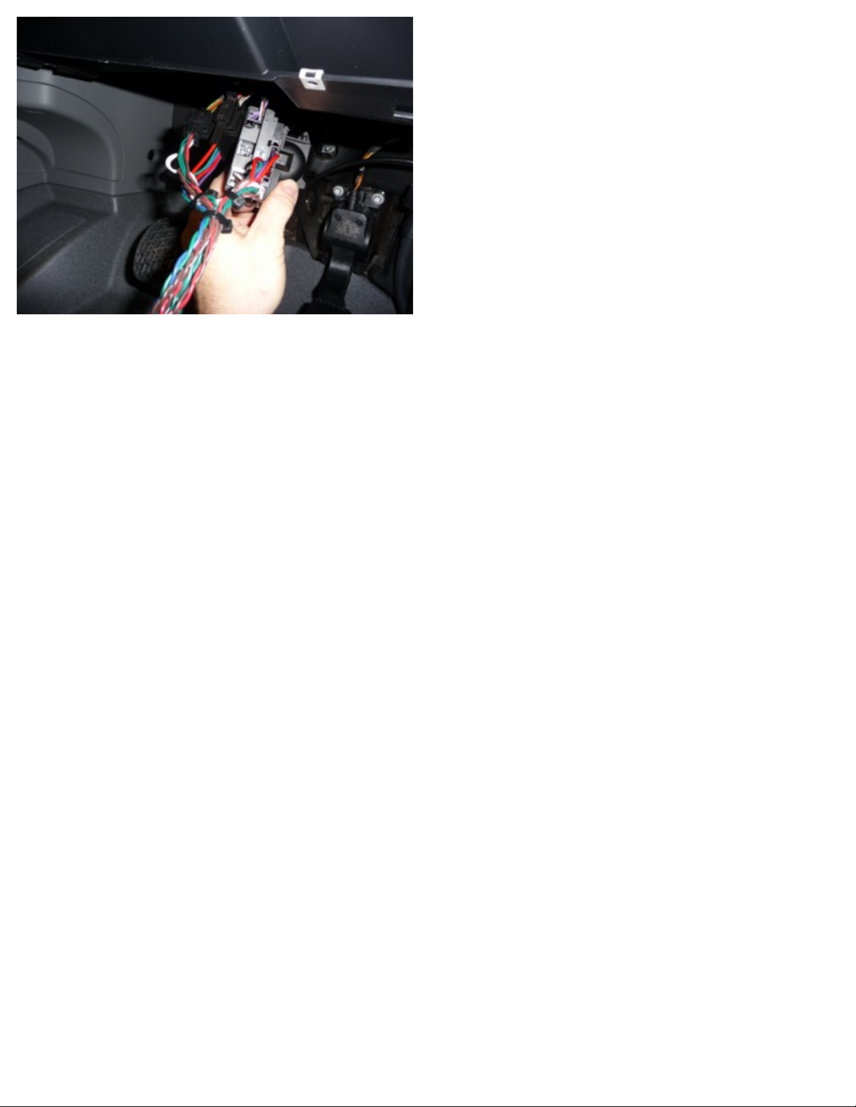
5. Reach up from the under dash and pull down the EIS module to access the wiring on the rear.
6. Remove the white (8) pin plug and the black (5) pin plug from the rear of the EIS.
7. Plug the T-harness in to the EIS and the factory wiring. (see diagram above)
8. Program your remote(s) or connect the data cable from an alarm/remote start system. (see alarm
connection section)
9. Start the vehicle and let it run for at least 30 seconds so the Smartkey Starter® can sync to the
vehicle.
10.Test the remote start operation.
11.Set the parking light option to be controlled by the starter (on) or not (off). There is an internal
modification that needs to be done. The default is (on). (see alarm connection section)
12.Reinstall the EIS and screw on the retaining ring.
13.Reinstall the under dash panels and the (3) T-25 screws that hold them in.
14.Drill a hole and mount the Valet switch in an easily accessible location.
Hood Pinswitch
The Mercedes Sprinter does not come with a factory hood pin. One can easily be added and tied into
the Smartkey Starter®. This should be done for your customer’s safety and is highly recommended.
This connection is not required if an alarm controller is used. The hood pin can be directly connected
to the alarm controller without the relay described below.
1. Mount the hood pin and confirm its operation.
2. Route the hood pin wire through the firewall to the under dash area.
3. Locate the brake pedal switch. Using a relay, the hood pin will be tied to the brake in order for the
remote start to shut down when needed.
4. Connect the hood pin wire to terminal 85 on the relay.
5. Connect the brake wire to terminal 30
6. Connect the ignition wire (from the brake switch supply) to terminal 86 and 87.
Using this connection, if the hood is opened and the ignition is on, the brake switch will be activated
and will not allow a remote start situation.
Copyright 2016 Midcity Engineering™ 2

Remove (3) T-25 Remove left dash panel
Remove main dash panel Remove EIS ring
EIS Ring Removed EIS connected at bottom of dash
Copyright 2016 Midcity Engineering™ 3

T-harness installed
Alarm Connection
The SKS906C Smartkey Starter® for Mercedes Benz Sprinter can be controlled directly from a
CM7000 Compustar Remote start/alarm combo controller. The SKS906D Smartkey Starter® for
Mercedes Benz Sprinter can be controlled directly from a D2D compatible Directed Electronics alarm/
remote start combo (i.e. Viper, Python, etc).
A. Data connection - Compustar
-A 4pin RS232 cable that would normally be used to connect an ADS Idatalink bypass module to a
Compustar controller is needed. The cable needs to be modified. On that specific cable, the colors
are Blue, White, Black, Red. The Blue and White need to be reversed so the polarity is opposite.
This can be done by removing the pins at one end and installing them in the opposite order. After the
modification, the wiring should be White, Blue, Black, Red at one end and Blue, White, Black, Red at
the other end. This cable will connect from the black port on the SKS906C to the black port on the
CM7000. If you are using a Drone in conjunction, it will connect to the gray port on the CM7000.
Copyright 2016 Midcity Engineering™ 4
Note: Cut the power (red wire) on the RS232 cable
Pictures for alarm connections (data, power, ground, ignition) can be
found in Sprinter (07-18) manual folder or at this link:
https://tinyurl.com/snl4pj6

Alarm Connection - DEI
A. Data connection
-A 4 pin D2D cable is required for connection between the SKS906D. The cable can be connected
directly at both modules without modification. If you are also connecting a SmartStart, that should be
connected directly to the DEI controller, NOT connected to the Smartkey Starter®.
-Signals being sent over data from the Smartkey Starter® to the alarm controller
-start
-door trigger
-trunk trigger
-lock
-unlock
-brake
-trunk release (side and rear door unlock only)
B. Analog connections
-The ignition wire from the alarm system needs to be connected to the key side of the T-harness. The
green wire on the T-harness is the ignition wire. A diode needs to be connected inline to the ignition
wire. The stripe should face the alarm brain.
-If you choose to utilize the light flash output from the alarm brain, the light output from the Smartkey
Starter® needs to be turned off. There is an internal modification that needs to be done. (See
pictures below) If the light flash is set to off, the parking light output from the alarm controller should
be used if external light flash confirmation is desired.
-Power (main module power, not the relay input power. If the relay input power is the only power
input to the alarm/remote start unit, the fuses should be changed to 10a maximum) and Ground need
to be connected from the alarm controller. These should be connected to the power and ground in
the Smartkey Starter® harness. Connecting power and ground elsewhere in the vehicle can result in
data communication errors between the Smartkey Starter® and the alarm/remote start brain.
-A hood pin should be installed for remote start safety as well as alarm protection.
C. Programming
The alarm controller needs to be set for tachless engine monitoring. Everything pertaining to the
remote start operation is handled by the Smartkey Starter®.
Copyright 2016 Midcity Engineering™ 5
Note: Cut the power (red wire) on the D2D cable
Pictures for alarm connections (data, power, ground, ignition) can be
found in Sprinter (07-18) manual folder or at this link:
https://tinyurl.com/snl4pj6

DEI Connection Instructions - XL202 + extended range remote and SmartStart
Each DEI compatible Smartkey Starter® is equipped with a (4) pin and a (3) pin connector at the end.
The (4) pin connector is designed to accept a D2D cable from an XL202 RF translator module to provide the
ability for adding long range remotes and 2 way capability to the Smartkey Starter®. There is no programming
required for the module. The remotes need to be programmed to the XL202 which should have instructions
provided with it.
The (3) pin connector is designed to accept the ESP cable that comes with the Directed SmartStart module
(DSM200/250 and DSM300/350). The cable can be plugged directly in to the port. The power and ground
must be connected (soldered and taped) to the Smartkey Starter® harness. Please see the below diagram.
!
Compustar Programming Instructions - antenna and extended range remote
To program any compatible Compustar remote control, complete the above basic installation steps and verify
standard operation. Install antenna and cable and connect to the appropriate blue port (4p or 6p) on the
SKS906C module.
Insert the key in the ignition switch and cycle it (5) five times from off to accessory (only one click in the
clockwise direction) and back to off.
The lights will flash once. Press lock or button 1 on the remote control and the lights will flash to confirm
programming. Up to (4) Compustar remotes can be programmed to one unit. If you are using a 2 way remote,
program that one first.
Once all remotes have been programmed, wait for a single light flash confirmation signifying the module has
exited programming mode.
Verify the operation of the new remote.
!
Compustar Drone Connection
Connect the Black data cable from the Drone to the Black Drone port on the Smartkey Starter®
SmartStart power
top row, first pin,
red
SmartStart ground
bottom row, first
pin, brown
DO NOT USE BLUE PORT FOR DRONE CONNECTION.
DRONE DATA CABLE MUST PLUG INTO BLACK PORT MARKED RS232.
!
Copyright 2016 Midcity Engineering™ 6

Light Flash Modification
Standard light flash No light flash
Copyright 2016 Midcity Engineering™ 7
Make connection between
end two solder points
Table of contents
Other Mid City Engineering Remote Starter manuals
Popular Remote Starter manuals by other brands

Directed Electronics
Directed Electronics AS-1271 user guide

Prestige
Prestige Platinum+ APS-597 installation manual

Mountain
Mountain MTN-12000 User manual & Safety instructions

ENERGEN
ENERGEN Power Jumper P4 User manual and safety guideline

Omega
Omega RS-6 Owner's Manual & Installation Instructions

Viatek
Viatek MJ10 Instructions for use