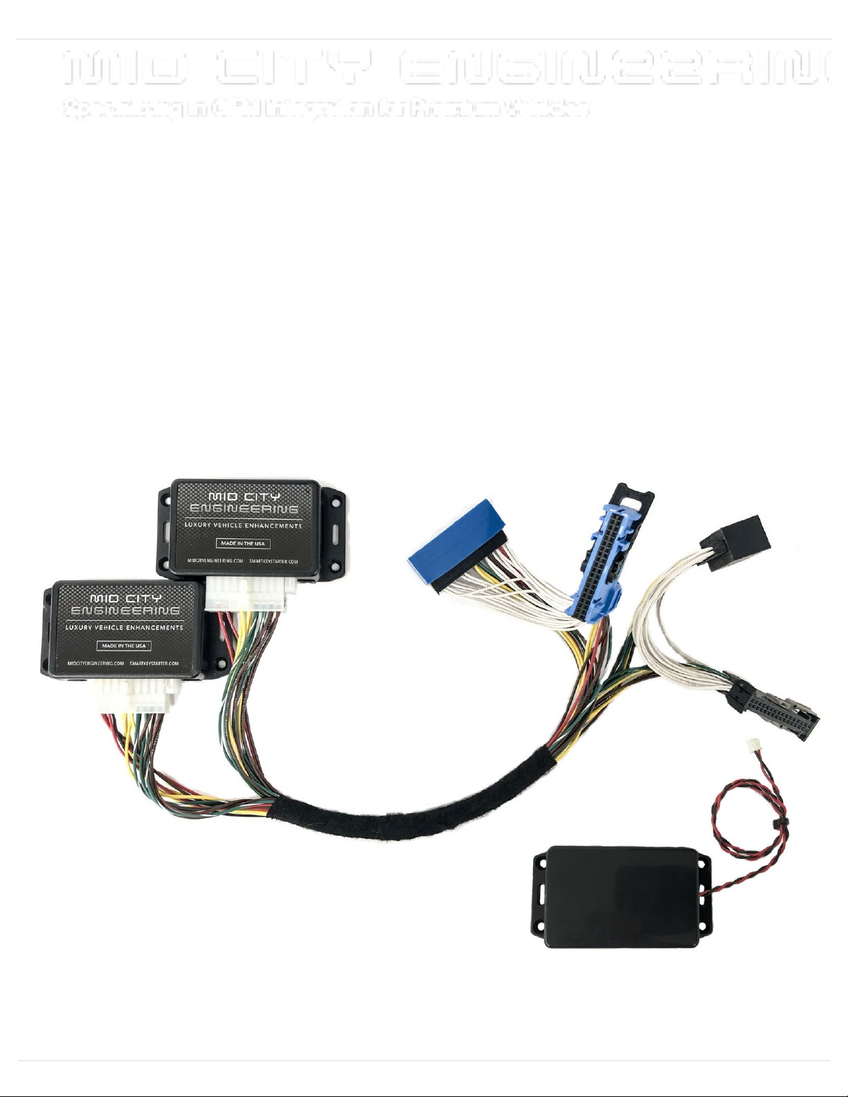
Mid City Engineering SKSNG907 User manual

SKSNG907 & SKSNG907RV Installation Manual
Installation manual for the SKSNG907 / SKSNG907RV remote start, high idle, and alarm for 2019
- 2022 Sprinter (907).
Written By: Noah Thatcher
SKSNG907 & SKSNG907RV Installation …
2022-11-03[minor]
V28
Release:Guide ID: 29 -
This document was generated on 2022-11-05 11:15:46 AM (MST).
© 2022 midcityengineering.dozuki.com/ Page 1 of 21

INTRODUCTION
ATTENTION: IF YOU ARE INSTALLING THIS SYSTEM ON A GASOLINE SPRINTER, PLEASE
MAKE SURE THAT THE SOFTWARE VERSION IS V5.23 OR ABOVE
The SKSNG907 is a remote start and alarm kit for the 2019-2022 Mercedes & Freightliner
Sprinter (907)
Link to product here.
Out of the box, the remote start will work using the factory key fob (lock-unlock-lock). It will also
include
OEM style alarm with no additional hardware. A Compustar DAS sensor can be plugged in to add
shock/tilt/vehicle movement protection to the alarm. The alarm will use the factory horn and flash the
parking lights. In addition, a full Compustar or Directed external alarm can be added.
For extended range, the Compustar Drone and Directed Smart Start can be added and will provide
2-way communication (including alarm notifications). All Compustar RF kits are compatible with the
system and any Directed RF kit using an XL202 (XL202 not needed if using Directed external alarm).
The remote start & alarm installation for the SKSNG907 or SKSNG907RV is 100% plug & play
and requires the following steps:
T-harness connection at PCM module
T-harness connection at EIS module
Key box installation
There is also a kit (SKSNG907RV) that also includes OEM style high idle and an optional external
trigger for start / stop. Link to that product here.
For further technical documents, including bypass jumper instructions, owners manual, error codes,
and option settings click here
PARTS:
SKSNG907 (1)
SKSNG907 & SKSNG907RV Installation …
2022-11-03[minor]
V28
Release:Guide ID: 29 -
This document was generated on 2022-11-05 11:15:46 AM (MST).
© 2022 midcityengineering.dozuki.com/ Page 2 of 21

Step 1 — Disconnect chassis battery ground
There is a battery quick disconnect
that should be used to disconnect
the chassis battery ground before
performing this bypass
The battery disconnect instructions
are for general reference only. For
instructions and chassis specific
details, refer to your vehicles owner
manual before performing this
disconnect.
The battery disconnect instructions
are for general reference only. For
instructions and chassis specific
details, refer to your vehicles owner
manual before performing this
disconnect.
Battery disconnect is located under
the driver side dash to the right of
the accelerator pedal
Remove access panel above and to
the right of the accelerator pedal
SKSNG907 & SKSNG907RV Installation …
2022-11-03[minor]
V28
Release:Guide ID: 29 -
This document was generated on 2022-11-05 11:15:46 AM (MST).
© 2022 midcityengineering.dozuki.com/ Page 3 of 21

Step 2 — Un-plug battery quick disconnect cable
Locate battery quick disconnect cable behind access panel
There is a red tab on the top of the disconnect cable. To release the cable from the post, the red
tab needs to be pushed downward
Push the red tab downward to release the cable and pull towards the rear of the cable at the same
time to remove cable from post
Carefully place battery disconnect cable to the side
Step 3 — Pull back weather seal
ATTENTION: IF INSTALLING THIS
SYSTEM ON A GASOLINE
SPRINTER, PLEASE MAKE SURE
THE FIRMWARE IS 5.23 OR
ABOVE
Pull back weather seal from driver
door jam
SKSNG907 & SKSNG907RV Installation …
2022-11-03[minor]
V28
Release:Guide ID: 29 -
This document was generated on 2022-11-05 11:15:46 AM (MST).
© 2022 midcityengineering.dozuki.com/ Page 4 of 21

Step 4 — Remove intermediate panel
Using a pry tool remove intermediate
panel between A pillar and kick
panel
Step 5 — Remove 2 x T20 screws from sill plate
Remove the 2 x T20 screws from
the sill cover
Remove sill cover and carefully set
aside
SKSNG907 & SKSNG907RV Installation …
2022-11-03[minor]
V28
Release:Guide ID: 29 -
This document was generated on 2022-11-05 11:15:46 AM (MST).
© 2022 midcityengineering.dozuki.com/ Page 5 of 21

Step 6 — Remove 1 x T20 from below hood release
Remove 1 x T20 from below hood
release
Step 7 — Remove 1 x T20 from bottom of kick panel
Remove 1 x T20 from bottom of kick
panel
SKSNG907 & SKSNG907RV Installation …
2022-11-03[minor]
V28
Release:Guide ID: 29 -
This document was generated on 2022-11-05 11:15:46 AM (MST).
© 2022 midcityengineering.dozuki.com/ Page 6 of 21

Step 8 — Remove plastic push fastener next to knee bolster
Remove plastic push fastener next
to knee bolster
Step 9 — Remove 2nd plastic push pin from kick panel
Remove plastic push pin from kick
panel (behind hood release)
SKSNG907 & SKSNG907RV Installation …
2022-11-03[minor]
V28
Release:Guide ID: 29 -
This document was generated on 2022-11-05 11:15:46 AM (MST).
© 2022 midcityengineering.dozuki.com/ Page 7 of 21

Step 10 — Remove 3rd plastic push fastener from kick panel
Remove 3rd plastic push fastener
from kick panel
Step 11 — Remove kick panel
Remove kick panel
Route hood release through kick
panel opening
Be careful of OBD harness
SKSNG907 & SKSNG907RV Installation …
2022-11-03[minor]
V28
Release:Guide ID: 29 -
This document was generated on 2022-11-05 11:15:46 AM (MST).
© 2022 midcityengineering.dozuki.com/ Page 8 of 21

Step 12 — Disconnect OBD harness
Disconnect OBD harness
Carefully route hood release through
opening and set trim piece panel
aside
Step 13 — Locate and un-clip PCM module
Un-clip PCM module from bracket in
back of kick area (towards driver
front tire)
SKSNG907 & SKSNG907RV Installation …
2022-11-03[minor]
V28
Release:Guide ID: 29 -
This document was generated on 2022-11-05 11:15:46 AM (MST).
© 2022 midcityengineering.dozuki.com/ Page 9 of 21

Step 14 — Connect T-harness to PCM module chassis harness
Locate black 32 pin plug on PCM
module
Unlatch and unplug black 32 pin
connector from PCM module
Plug connector into mating black 32
pin plug on T-harness
Step 15 — Connect 32 pin plug from T-harness to PCM module
Connect and latch 32 pin black plug
from T-harness into PCM module
where plug was removed in last step
SKSNG907 & SKSNG907RV Installation …
2022-11-03[minor]
V28
Release:Guide ID: 29 -
This document was generated on 2022-11-05 11:15:46 AM (MST).
© 2022 midcityengineering.dozuki.com/ Page 10 of 21

Step 16 — Connect T-harness to EIS module chassis harness
Locate EIS module in driver kick
(mounted to exterior wall below A
pillar)
Unlatch and unplug 40 pin blue
connector from top of EIS module
Connect 40 pin blue connector from
EIS to mating connector on T-
harness
Step 17 — Connect T-harness to EIS module
Connect and latch blue or red 32 pin
connector from T-harness to top of
EIS module where plug was
removed in previous step
SKSNG907 & SKSNG907RV Installation …
2022-11-03[minor]
V28
Release:Guide ID: 29 -
This document was generated on 2022-11-05 11:15:46 AM (MST).
© 2022 midcityengineering.dozuki.com/ Page 11 of 21

Step 18 — Remount PCM module
Place and clip PCM module back
into bracket
Step 19 — Install battery emulator into key
Remove battery from extra factory
fob
One side of the battery emulator has
a foam strip and text that reads
‘BOTTOM OF KEY’
Insert the battery emulator in the
battery cavity of key with side that
reads ‘BOTTOM OF KEY’ facing
the side of the key with no
buttons
SKSNG907 & SKSNG907RV Installation …
2022-11-03[minor]
V28
Release:Guide ID: 29 -
This document was generated on 2022-11-05 11:15:46 AM (MST).
© 2022 midcityengineering.dozuki.com/ Page 12 of 21

Step 20 — Install button pusher and close key box
IMPORTANT: When installing the
key in the box, make sure that the
plastic insert in the key box is
pushing DOWN on the UNLOCK
button. The insert must be holding
the UNLOCK button DOWN on the
key when the box is closed
Put key inside box and slide button
pusher over the center of the
UNLOCK button
Put lid on box and fasten the 4
screws. Confirm that the unlock
button on the key is being pressed
when the box is closed
Step 21 — Connect key box to SmartKey Starter module
Connect the 2 pin white plug from
the key box to the 2 pin white port
labeled ‘KEY’ on the module labeled
‘SmartKey Starter’
SKSNG907 & SKSNG907RV Installation …
2022-11-03[minor]
V28
Release:Guide ID: 29 -
This document was generated on 2022-11-05 11:15:46 AM (MST).
© 2022 midcityengineering.dozuki.com/ Page 13 of 21

Step 22 — Install hood pin
SKSNG907 and SKSNG907RV version 5.26 and up include a hood pin.
Mount hood pin under hood in location that will ground (close) the pin when the hood is open, and
open the pin when the hood is closed
Run wire from hood pin securely through firewall and run to driver side under dash area
Connect included 6 pin pigtail into white 6 pin port on module labeled ‘SKSPCM’
Connect hood pin wire to gray wire on 6 pin pigtail
Insulate all other wires on 6 pin pigtail that are not being used in other application (expansion port
covered later in installation instructions)
SKSNG907 & SKSNG907RV Installation …
2022-11-03[minor]
V28
Release:Guide ID: 29 -
This document was generated on 2022-11-05 11:15:46 AM (MST).
© 2022 midcityengineering.dozuki.com/ Page 14 of 21

Step 23 — Re-connect chassis battery disconnect cable
Reconnect battery disconnect cable from to post from step 2
Ensure that cable locks into place on post. You should feel the tab lock into place. Once
connected, you should not be able to remove cable from post without pressing red tab downward
Step 24 — Test remote start operation
Make sure that vehicle is in a safe
place to start engine
Close all doors on vehicle
On factory key fob, hit ‘LOCK-
UNLOCK-LOCK’ buttons in
sequence.
SKSNG907 & SKSNG907RV Installation …
2022-11-03[minor]
V28
Release:Guide ID: 29 -
This document was generated on 2022-11-05 11:15:46 AM (MST).
© 2022 midcityengineering.dozuki.com/ Page 15 of 21

Step 25 — Test hood pin
Open hood and attempt remote start
Make sure that remote start is disabled when hood is open
Step 26 — Test key takeover
After remote start, enter vehicle with key and place foot on the brake then press push to start
button
Engine will quickly shut down and restart after you press the button- after that, you can shift into
gear
SKSNG907 & SKSNG907RV Installation …
2022-11-03[minor]
V28
Release:Guide ID: 29 -
This document was generated on 2022-11-05 11:15:46 AM (MST).
© 2022 midcityengineering.dozuki.com/ Page 16 of 21

Step 27 — Test alarm
Roll down driver side window
From outside vehicle, close and lock
doors with factory key fob
Reach inside driver window and
open door from inside handle
Alarm should sound (factory horn)
and lights should flash
Press unlock on factory remote to
disarm alarm
Step 28 — Mount modules and re-assemble vehicle
Mount SmartKey Starter® and
SKSPCM module in secure location.
Suggested location is to wiring
harness in driver under dash
Mount key box in secure location. It
is recommended to mount the key
box further up into dash area for
additional key security
Mount all modules away from any
heat sources or moving parts
Re-assemble vehicle in reverse
order of disassembly steps
SKSNG907 & SKSNG907RV Installation …
2022-11-03[minor]
V28
Release:Guide ID: 29 -
This document was generated on 2022-11-05 11:15:46 AM (MST).
© 2022 midcityengineering.dozuki.com/ Page 17 of 21

Step 29 — Install warning sticker
The provided warning sticker must
be installed in this location or your
SmartKey Starter® warranty will be
voided
Install provided warning sticker on
intermediate panel between A pillar
and kick panel
Step 30 — OPTIONAL: External device connection
For Compustar Drone connection, click here
For Directed Smart Start Connection, click here
For Compustar RF remote connections, click here
For Compustar external alarm connection, click here
For Compustar DAS sensor connection, click here
For Directed external alarm connection, click here
SKSNG907 & SKSNG907RV Installation …
2022-11-03[minor]
V28
Release:Guide ID: 29 -
This document was generated on 2022-11-05 11:15:46 AM (MST).
© 2022 midcityengineering.dozuki.com/ Page 18 of 21

Step 31 — OPTIONAL: Expansion port connections
The SKSNG907 and SKSNG907RV with software version 5.26 and up include a 6 pin expansion
port and pigtail. This is a 6 wire pigtail with a white plug. The gray wire is used for hood pin
(required), as covered in step 20. With this port, you can also add optional expansions:
Physical valet switch (remote starter on/off). When purple wire is grounded, system is in valet
mode (remote starter off)
External siren. Brown wire provides siren output (+) for use with included alarm
High idle off input (disables high idle during remote/auto start). Note: only available for
SKSNG907RV. When yellow wire is grounded, high idle will be disabled during remote/auto
start.
Shock/tilt sensor disable. Note: only if Compustar DAS sensor is added. When orange wire is
grounded, DAS sensor will be disabled.
Black wire is used to supply a ground for siren and/or for use with a switch to use any of the above
inputs
The gray wire is the hood pin input. This is not optional and covered in step 20.
Solder and insulate all connections. Insulate exposed end of any wire on this pigtail that is not
used.
SKSNG907 & SKSNG907RV Installation …
2022-11-03[minor]
V28
Release:Guide ID: 29 -
This document was generated on 2022-11-05 11:15:46 AM (MST).
© 2022 midcityengineering.dozuki.com/ Page 19 of 21

Step 32 — OPTIONAL: START/STOP TRIGGER FOR SKSNG907RV
The SKSNG907RV includes an analog start/stop trigger to operate the remote start from an
external trigger. The cable has a white 4 pin plug and, if using external start/stop triggers, will plug
into the white or green 4 pin plug labeled ‘Trigger Input’ on the module labeled ‘SKSPCM.’ Refer
to this diagram for wiring.
The trigger has 2 configurations, 1 wire or 2 wire. The 1 wire configuration (default) will start the
engine when the start wire is grounded (green). The 2 wire configuration has a separate start wire
(green) and stop wire (white). In the 2 wire configuration, a momentary ground on the start/stop
wires will execute the command
The 1 wire configuration is the default setting. To change to the 2 wire configuration, you can use
the SmartKey Starter® menu. The trigger configuration is in the hidden menu. For menu
instructions refer to owners manual
Note: when using this auto start with external 1-wire trigger (latched ground to start and
run) the system will re-start if ground is still applied to start wire after run-time
expiration. The system will continue running and re-starting until external trigger
removes ground signal.
For Sprinters without the volume and mute buttons on the steering wheel, you will need to use a
USB programming tool to change this setting
If analog input(s) not being used, the 4 pin white input cable should not be plugged into the
SKSPCM module.
SKSNG907 & SKSNG907RV Installation …
2022-11-03[minor]
V28
Release:Guide ID: 29 -
This document was generated on 2022-11-05 11:15:46 AM (MST).
© 2022 midcityengineering.dozuki.com/ Page 20 of 21
This manual suits for next models
1
Other Mid City Engineering Remote Starter manuals
Popular Remote Starter manuals by other brands

Duracell
Duracell 854-1707-07 instruction manual

Mopar
Mopar 82215575AB manual

Deltran
Deltran Battery Tender 030-0006 instruction manual

Omega
Omega RS-3A Operating & installation instructions

Directed Electronics
Directed Electronics PS-4661TWE-FM user guide

Etable
Etable ETABLE E1227 Safety & operation manual