Mid-Continent Instrument MD23-104 User manual

User Guide
For
MD23-104
True Blue Power
Gen5 Lithium-ion Battery Monitor
powered by
Rev Date Detail Approved
2 04/06/2022 Updated user interface in 4.1.1. BAW
3 12/19/2022 Updated for addition of clock displays KC
4 01/09/2023 Minor corrections. Clock configuration instructions added BAW
This manual provides information intended for use by persons who, in accordance with current
regulatory requirements, are qualified to install this equipment. It is a supplement to the MD23
Installation Manual and Operating Instructions, p/n 9019161.
If further information is required, please contact Mid-Continent Instruments and Avionics.
Mid-Continent Instruments and Avionics Mid-Continent Instrument Co., Inc.
dba Mid-Continent Instruments and Avionics
9400 E. 34th Street N.
User Guide UG104 Wichita, KS 67226 USA
Revision 4 ph (800) 821-1212 www mcico.com
www mcico.com

MD23 FLEX
User Guide
Mid-Continent Instruments and Avionics 2 User Guide UG104, Revision 4
January 9, 2023
1.1 INTRODUCTION
The model MD23 series FLEX® Custom Function Display (“CFD”) is a standard 2-inch (2-¼”)
panel-mounted instrument that displays multiple inputs in a configurable graphical presentation.
FLEX® is an off-the-shelf solution that is FAA and EASA TSO-approved with Level A design
assurance software certification. The patented software concept allows customization to your
requirements by Mid-Continent Instruments and Avionics without additional product certification.
With the ability to receive and send multiple types of inputs and outputs, allow user interface, and
display custom designed graphics, FLEX® is as flexible as it gets.
This User Guide is a supplement to the Installation Manual and Operating Instructions (IM),
MCIA part number 9019161. The IM contains all information associated with the standard
product, including installation procedures, product specifications, operating instructions,
certification data, and maintenance requirements. This User Guide provides additional
information associated with the customized version of the MD23 that is specific to each
application and requested requirements. It addresses product identification, electrical pinout,
initial configuration setup (if applicable), and in-flight user operation.
1.2 PRODUCT IDENTIFICATION
Each MD23 is comprised of certified hardware and certified software. Within the context of the
certified software is a set of data items that can configure and customize the behavior of the unit.
This set of data is referred to as a Custom Instrument Definition, or a CID file, and can be
installed via a standard USB flash drive through the programming port on the rear of the unit.
A unique CID number has been assigned specifically to this application. The CID is identified by
its four-digit number and a fifth alphabetic character representing the CID version, starting with
“A”. A sixth numeric digit may be used to represent pre-released versions of the CID.
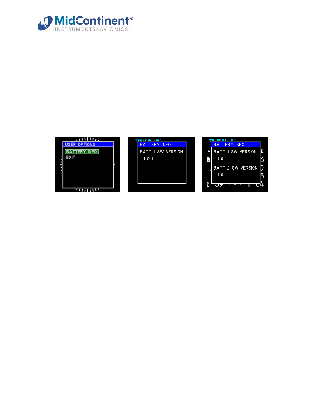
The identification of the hardware, software, and CID configurations are listed below. Both the
software version and the CID can be viewed on the Introduction Screen during the first few
seconds of applying power to the unit. This information can also be accessed on the Info page of
the Options Menu during Flight Mode.
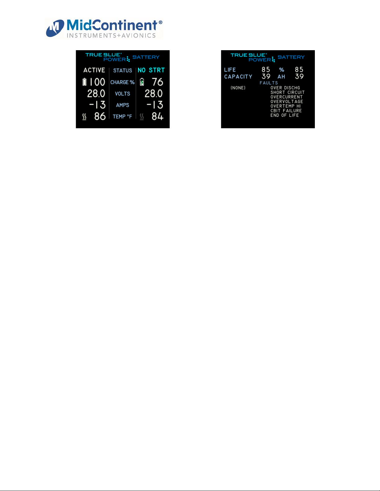
1.3 PRODUCT FUNCTION
The CID identified within this User Guide is designed to function as a battery monitor for the True
Blue Power Gen5 family of Advanced Lithium-ion Batteries as well as a local time clock and flight
timer. The unit can be configured to monitor one battery or two. The display provides status,
voltage, current, state of charge, and temperature based on ARINC 429 inputs from the battery.
Additional details can be found on a secondary status page including Remaining Life, Battery
Capacity, and detailed faults, when present. Variable thresholds and alerts, if programmed on
the battery, will also be displayed. All ARINC data provided by the Battery 1 inputs will be re-
Unit Versions
Hardware Part Number Software Version CID
6420023-1, or
6420023-21
1.1.0, or later 04B or later

MD23 FLEX
User Guide
Mid-Continent Instruments and Avionics 3 User Guide UG104, Revision 4
January 9, 2023
broadcast on the ARINC output as well. The clock and flight timer displays can each be enabled
or disabled via configuration options.
2.1 CONNECTOR PINOUT
For standard pre-installation and installation instructions, including location, cable harness
assembly, pneumatic inputs (if applicable), mounting, and others, please refer to the IM.
Pinout identification specific to this CID is listed in the table below. A brief description is provided.
Further definition of the inputs and outputs should be documented in the technical requirements
and/or statement of work and are not provided within this User Guide.
Connector Pinout
Pin Description Function
1 Ground Power return; connect to a/c gnd
2 ARINC Out (A) Rebroadcast of
A
RINC In 1 data
3 ARINC Out (B) (see pin 2)
4 Dimmer Input 5, 14, or 28VDC input (if used)
5 ARINC In 1(A)
A
RINC In from Battery 1
6 ARINC In 2(A)
A
RINC In from Battery 2 (if used)
7 Reserved
8 Reserved
9 Reserved
10 Reserved
11 Flight Timer
Input / WoW
Start: Ground signal (in air)
Stop: Open
/
no signal (on ground)
12 Reserved
13 Reserved
14 ARINC In 1(B) (see pin 5)
15 Reserved
16 ARINC In 2(B) (see pin 6)
17 Reserved
18 Reserved
19 Power Input +10-32VDC
20 Reserved
21 Reserved
22 Reserved
23 Reserved
24 Reserved
25 Reserved
26 Reserved
Table 1 Unit Connector Pin Identification

MD23 FLEX
User Guide
Mid-Continent Instruments and Avionics 4 User Guide UG104, Revision 4
January 9, 2023
3.1 CONFIGURATION AND SETUP
Enter Configuration Mode by pressing and holding the Control Knob while applying power to the
unit. For configuration and setup of standard unit functions, including dimming control options
and dimming curve definition, please refer to the IM.
Configuration settings specific to this CID are found within the User Configuration menu. There
are four user configuration items: Battery Count (one or two), Clock display (on or off), Flight
Timer display (on or off), and Start Page. The Start Page option allows the instrument to be
configured to start on the Clock display page, the Flight Timer display page, or the main Battery
status display page when initially powered. The current setting for each of these configuration
items is shown on the right side of the display.
Highlight a setting by turning the Control Knob and pressing to enable the selection. When
presented with options, turn the Control Knob to select the desired setting for that item and press
again to select and return to the main Config Options menu. The four User Configuration items
and their available options are shown in the images below. After configuring these options as
desired, highlight EXIT and press the knob to return to the main Configuration menu.
From the Configuration Menu, selecting EXIT again will automatically reset the unit and start in
normal mode.
(Battery Count config options) (Clock Display config options)

MD23 FLEX
User Guide
Mid-Continent Instruments and Avionics 5 User Guide UG104, Revision 4
January 9, 2023
4.1 OPERATION
For operation of standard unit functions, including the Options Menu, manual brightness control,
Info page, and others, please refer to the IM.
For details associated with the custom battery functions beyond those identified here, refer to the
True Blue Power Install Manual and Operating Instructions for the specific battery associated
with your application.
In Flight Mode, there are four display screens available. These are:
1. main battery status display screen
2. secondary battery status display screen
3. local time analog clock display screen (optional),
4. local time digital clock display and flight timer screen (optional)
Turn the knob to rotate through these screens.
When on one of the battery status screens, a short press of the Control Knob changes the
display immediately to the clock display screen, if enabled.
(power on screen)
4.1.1 BATTERY DISPLAY SCREENS
(page 1 – one battery) (page 2 – one battery)

MD23 FLEX
User Guide
Mid-Continent Instruments and Avionics 6 User Guide UG104, Revision 4
January 9, 2023
(page 1 – two batteries) (page 2 – two batteries)
Individual elements are defined as follows:
Page 1
o Status: Displays battery status: Active, Fault, Service, Invalid, or No Start
o Charge %: Displays current state of charge. 0-100%
Number is amber if state of charge is below battery-programmed minimum
Battery Icon represents state of charge and depletes in relation to charge %
Icon is amber if state of charge is below battery-programmed minimum
Icon contains green lightning bolt when battery is charging
o Volts: Current voltage of the battery
Number turns amber when under-voltage or over-voltage
o Amps: Discharge or charge current (discharge current denoted as negative (-))
Number turns amber if an overcurrent fault exists
o Temp: Internal temperature of the battery, in degrees Celsius
Number is red if temperature exceeds the upper limit of the battery
Heater Icon represents the current state of the battery heater
Icon is a gray horizontal bar if heater is inactive/offline
Icon is a gray bar with squiggles if heater is active/available
Icon is a white bar with squiggles if heater is current on/heating
Page 2
o Life: Remaining percentage between original max and battery-programmed
end of life capacity. 0-100%
o Capacity: Current maximum capacity of the battery. Number is amber if capacity
is below the battery-programmed end of life capacity.
o Faults: Reported battery faults. “(None)” if none.

MD23 FLEX
User Guide
Mid-Continent Instruments and Avionics 7 User Guide UG104, Revision 4
January 9, 2023
4.1.2 CLOCK DISPLAY SCREEN
When enabled the clock display screen shows a traditional analog clock face with a
sweeping second hand as shown in the image below.
Pressing the Control Knob will display a prompt to set the time. To enter Set Mode, confirm by
pressing again or the prompt will time out and return to normal operation after five (5) seconds.
In Set Mode, set the hours, minutes, and seconds, consecutively. After turning the Control
Knob to set each, press the knob to confirm and move to the next selection.
While setting the hours, AM or PM will be displayed in the upper left corner.
While setting the seconds, the message “TURN TO ZERO” will appear. Pressing the knob
will exit the Set Mode without changing the seconds. Turning the knob a single click/detent
will reset the seconds to zero and return the minutes hand to the beginning of the current
minute. This allows you to synchronize the clock with an external time source. (If
setting/synchronizing seconds, it may be helpful to set the minutes to the upcoming minute in
the previous step.) After resetting the seconds, pushing the Control Knob will exit Set Mode
and return to normal operation.

MD23 FLEX
User Guide
Mid-Continent Instruments and Avionics 8 User Guide UG104, Revision 4
January 9, 2023
4.1.3 FLIGHT TIMER DISPLAY SCREEN
The flight timer display screen, when enabled, displays the local time (hours and minutes)
and elapsed flight time (hours and minutes) using digital numeric displays. The local time is
displayed in either 12- or 24-hour time format. See the images below.
The flight timer will run whenever the Flight Timer Input is active (active = ground signal = in-
flight). When the flight timer is running, the colon blinks twice a second and displays seconds
for the first sixty (60) seconds. When the Flight Timer Input is inactive (inactive = open = on-
ground), the colon stops blinking, the timer stops, and the message “PRESS TO RESET” is
displayed. The time is retained during power cycles if not reset and will begin counting again
when the Flight Timer Input becomes active again.
Pressing the Control Knob on the Flight Timer Screen offers two options. From this menu,
turn to select either “PUSH TO SET TIME” or “PUSH TO RESET TIMER” and press to
confirm. The Flight Timer reset is only available when the Flight Timer Input is inactive. The
menu will disappear after five seconds and return to normal operation.
(Enter SET TIME) (Enter RESET TIME)
When setting the time, turn the knob to change the green highlighted hours. (note: the default
for setting the digital time is 24-hour mode. This can be changed at the end of the time-set
process) Press to confirm the hours setting and then repeat the process to set the minutes.
The final selection allows the choice of 12- or 24-hour mode by turning, then pressing the
knob.

MD23 FLEX
User Guide
Mid-Continent Instruments and Avionics 9 User Guide UG104, Revision 4
January 9, 2023
(Set hours) (Set minutes) (Select 12/24 hour mode)
When resetting the flight timer, select “PRESS TO RESET” and press the Control Knob from
the popup menu. A five second countdown timer will start running. Press the Control Knob
again to reset the flight time. The timer will not be reset if the timer expires, returning to
normal operation.
4.1.4 BATTERY STATUS CHANGE ALERT
When either the Clock or Flight Timer Display Screens are active and the Battery Status
Indicator changes to anything other than ACTIVE, or if the ARINC data stream from the
battery or batteries is no longer being received properly, an alert popup will appear to notify
the user that this has occurred. See the images below.
Press the knob button while this alert is being displayed to immediately switch to the main
Battery Status Display Screen or simply wait and the display will switch automatically when
the countdown expires.
Note that this alert will only be shown once per power-up. If the fault clears or data is
reacquired and then another fault occurs, or data is lost again, the alert will not be shown,
and the display will not switch to the battery status display screen.

MD23 FLEX
User Guide
Mid-Continent Instruments and Avionics 10 User Guide UG104, Revision 4
January 9, 2023
4.1.5 USER OPTIONS
Pressing and holding the Control Knob for three (3) seconds will activate the Options Menu.
The manual brightness adjustment and info page are described in the IM. The Options Menu
or User Options items will close and return to the active display after ten (10) seconds if no
knob activity is detected.
When highlighted and selected, the User Options item will open a new page and display the
available options available to the pilot. The only User Option for this instrument is Battery
Info. When BATTERY INFO is selected, the unit will display the current software version
installed in the battery (or batteries).
Press the knob button to return to the User Options Menu or simply wait ten (10) seconds
and the unit will return to the active Flight Mode display.
5.1 CONFORMANCE
For standard conformance items such as qualification levels and software updates, please refer
to the IM.
5.1.1 INSTRUCTIONS FOR CONTINUED AIRWORTHINESS
No periodic scheduled maintenance or calibration is necessary for continued airworthiness of
the MD23 Custom Function Display, unless specified in the aircraft maintenance procedures.
The unit display can be cleaned using a lint-free cloth moistened with water. No chemicals
should be used to clean the display.
If the unit fails to perform to specifications, the unit must be removed and serviced by Mid-
Continent Instruments and Avionics or their authorized designee. Other than software version
updates, there are no repairable parts or processes available to be performed in the field.
Table of contents
Other Mid-Continent Instrument Measuring Instrument manuals