Middleby Bluezone 450 Setup guide


Document #: BPI-PM004-01
1
IMPORTANT SAFEGUARDS
READ AND SAVE THESE INSTRUCTIONS
Safety
This manual contains important instructions
and safety information about the Bluezone Air
Purification System. Observe the following
dangers, warnings, cautions and notices
when installing, operating and servicing the
Bluezone Model 450.
Electrical System
Energized electrical circuits present a
potentially life-threatening hazard.
Ensure the unit’s power cord is unplugged
before performing any installation or service
work.
Ensure there are no other electrical power
circuits connected to the Bluezone Model
450.
Do Not Operate unit with a damaged cord or
plug. Discard unit or return to an authorized
service facility for repair.
Follow all lockout/tagout procedures for all
electrical circuits.
System Operation
Do not operate the Bluezone Model 450
while fogging with chlorine bleach or other
disinfectant solutions. Disinfectants can
poison the Bluezone catalyst and reduce its
effectiveness.
•Turn off the Bluezone Units if
disinfectant fogging or cleaning is
underway.
•Turn Bluezone units back on after
disinfectants have dissipated.
Never hose down the Bluezone Model 450 or
clean with a water jet. Direct flow of water
onto the catalyst can reduce its effectiveness
in eliminating ozone.
Turn off Bluezone units and cover with plastic
if the room is being hosed with water or
steam.
System Maintenance
The Bluezone Model 450 contains 4 UV-C
light bulbs; the UV light is completely
contained inside the unit during operation.
Unplug or disconnect the unit from power
source prior to any servicing.
The Bluezone Model 450 has multiple safety
systems to ensure that you cannot view the
UV bulbs while they are operating.
Do NOT attempt to override the cover switch
to allow the bulbs to operate when the cover
is off.

Document #: BPI-PM004-01
2
Skin or eye damage may result from directly
viewing the light produced by the lamp in this
apparatus. Always disconnect power before
relamping or servicing. Replace lamps using
Lamp Replacement Kit Model No. 005-
000004, manufactured by Bluezone Products
Inc. and sold by Authorized Bluezone Partner.
Never look at an illuminated UV-C bulb
without proper eye protection against UV light
frequencies.
Description
The Bluezone® Model 450 is an air
purification device that eliminates airborne
contaminants including microbes (virus, fungi,
mold and bacteria) and odors.
The Model 450 can be installed into a
standard 2’x4’ tile or two 2’x2’ ceiling tiles with
a ceiling mounting kit, installed into Bluezone
by Middleby cabinetry,or located on a shelf.
The Bluezone Model 450 draws in air
containing viruses, mold, spores or fungus,
and discharges air with a highly reduced
concentration of these infectious impurities.
The unit is completely self-contained. The
facility, equipment, and personnel have no
contact with the process that is cleaning the
air.
The Bluezone unit’s operation is controlled by
a microprocessor-based controller that
ensures safe operation at all times and alerts
the user to any system faults.
Specifications
The specifications of the Bluezone Model 450
are shown in Table 1.
Table 1: Bluezone Model 450
Specifications
Specification Category
Model 450
Size
31” X 15” X 13 3/8”
79cm X 38 cm X 34 cm
Product Weight
26 lbs./11.8kg
Shipping Size
36” X 20” X 20”
91cm X 51cm X 51cm
Shipping Weight
29 lbs/13.2 kg
Storage Environment
-4°F –150°F
-20C –65C
Input Voltage
120 VAC 1 Phase
Or
240 VAC 1 Phase
Current
3 amps at 120 VAC
1.5 amps at 240 VAC
Power
350 Watts max
Electrical Connection
IEC 320-C13 power cord
Mounting Options:
Installed in ceiling mount kit,
cabinetry, or placed on shelf
Certifications
cETLus Listed
ARB certified –Zero Ozone
CE Mark
Document #: BPI-PM004-01
3
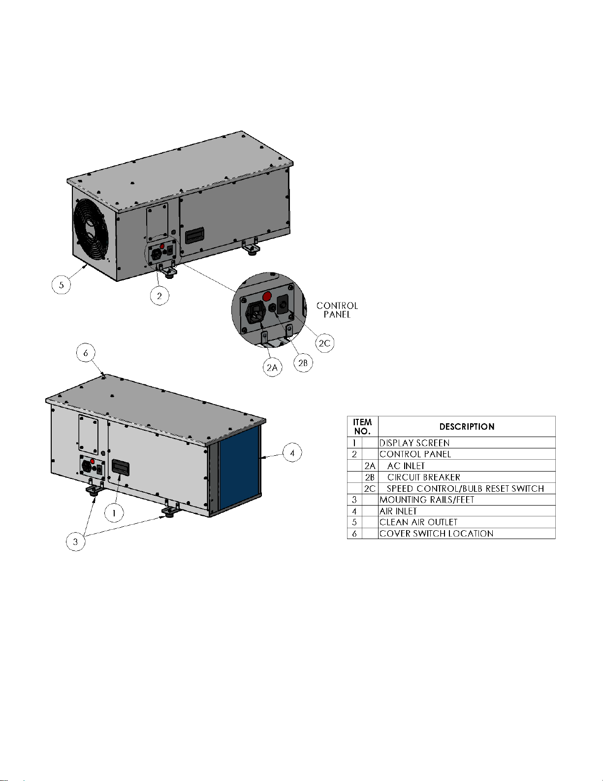
Key Components
Figure 1: Bluezone Model 450 Key Components
Document #: BPI-PM004-01
4
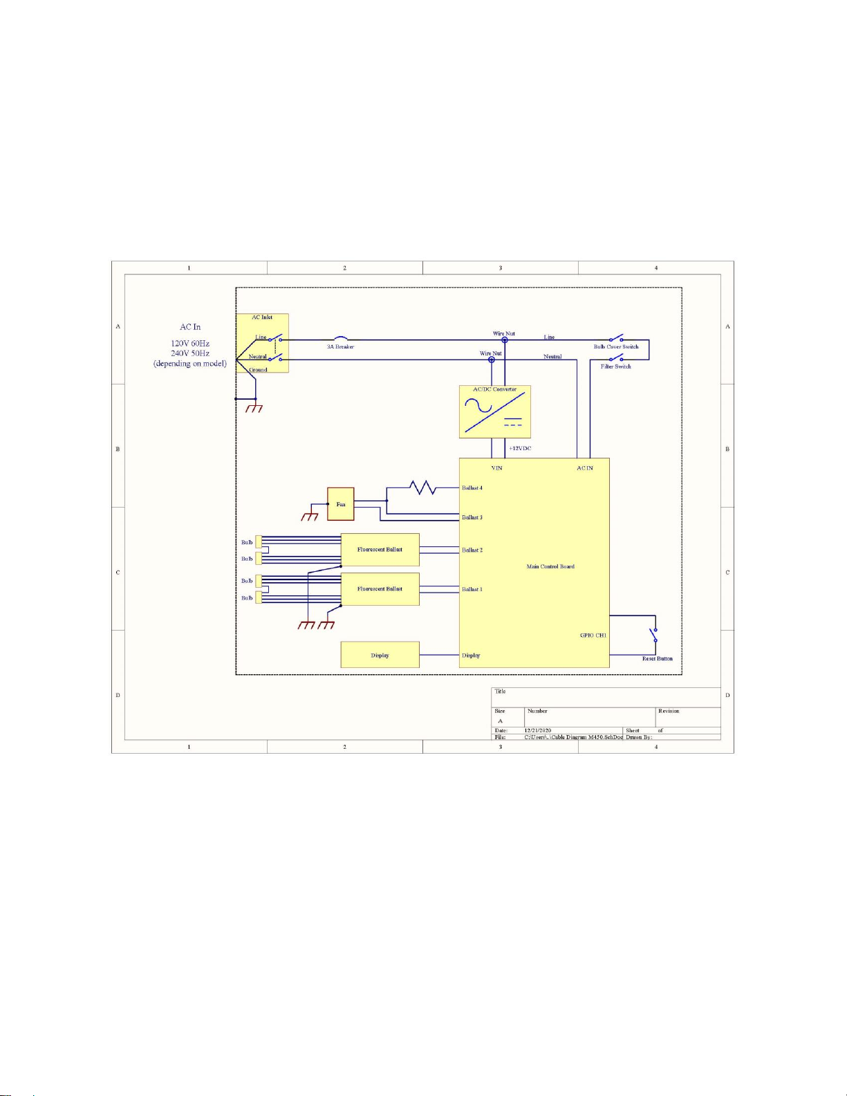
Electrical System
A wiring diagram of the Model 450 is shown in Figure 2. The wiring diagram applies to both the
120V and 240V SKUs of the Model 450. The asset tag on the Model 450 identifies the required
voltage.
Figure 2: Wiring Diagram of the Model 450-052 (120V) and Model 450-055 (240V)


