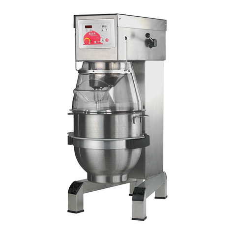
Middleby Varimixer V Series User manual

V
V30
V40
V40P
V60
V60P
Varimixer
2215 East River Road
Dayton, OH 45439, US
P: (800) 222-1138
E: mixer@varimixer.com
www.varimixerusa.com
EN
Operating Instructions
Valid from machine number:
V30: 30007634
V40: 40008430
V60: 60007226
DRN: 20030-1336
Original user manual
2020 12 20

Limited Mixer Warranty
VARIMIXER warrants to the original purchaser of new equipment that said equipment, when installed in accordance
with our instructions within North America and subjected to normal use, is free from defects in material or workmans-
hip for a period of 2 years. Wear parts, such as belts, are excluded. Hub attachments, such as shredders, slicers and
grinders have a 1 year warranty that only covers parts. Warranty begins on date of factory shipment to an end user, or
up to 6 months after factory shipment to a dealer or distributor. Payment by VARIMIXER for service under this warranty
requires that service be authorized in advance. Contact VARIMIXER Technical Support to arrange for service.
THIS WARRANTY IS IN LIEU OF ALL OTHER WARRANTIES, WHETHER EXPRESSED OR IMPLIED. VARIMIXER
EXPRESSLY DISCLAIMS ANY IMPLIED WARRANTY OF MERCHANTABILITY OR EXPRESSED OR IMPLIED
WARRANTY OF FITNESS FOR A PARTICULAR PURPOSE.
VARIMIXER’S OBLIGATION AND LIABILITY UNDER THIS WARRANTY IS EXPRESSLY LIMITED TO REPAIRING
AND REPLACING EQUIPMENT WHICH PROVES TO BE DEFECTIVE IN MATERIAL OR WORKMANSHIP WITHIN
THE APPLICABLE WARRANTY PERIOD. All repairs pursuant to this Warranty will be performed by an Authorized
Designated VARIMIXER Service Location during normal working hours. IN NO EVENT SHALL VARIMIXER BE LIA-
BLE FOR INCIDENTAL OR CONSEQUENTIAL DAMAGES TO BUYER OR ANY THIRD PARTY, INCLUDING, WIT-
HOUT LIMITATION, LOSS OF PROPERTY, PERSONAL INJURY, LOSS OF BUSINESS OR PROFITS OR OTHER
ECONOMIC LOSSES, OR STATUTORY OR EXEMPLARY DAMAGES, WHETHER IN NEGLIGENCE, WARRANTY,
STRICT LIABILITY, OR OTHERWISE.
This warranty is given only to the rst purchaser from a retail dealer. No warranty is given to subsequent transferees.
This warranty does not cover product failures caused by: failure to maintain, neglect, abuse, damage due to excess
water, re, normal wear, improper set up and use. Periodic maintenance is not covered.
Example of items not covered under warranty, but not limited to just these items:
1. Acts of God, re, water damage, vandalism, accident, theft.
2. Freight damage.
3. Improper installation or alteration of equipment.
4. Use of generic or after market parts.
5. Repairs made by anyone other than a VARIMIXER designated servicer.
6. Lubrication.
7. Expendable wear parts. (This includes the bowl, at beater, wire whip, spiral dough hook,
and the pastry knife.)
8. Cleaning of equipment.
9. Misuse or abuse.
This warranty is not in force until such time as a properly completed, digitally signed Installation/Warranty Registration
has been received by VARIMIXER within 30 days from the date of installation.
Register online at www.varimixerusa.com/support/warranty-registration-form.
THE FOREGOING WARRANTY PROVISIONS ARE A COMPLETE AND EXCLUSIVE STATEMENT BETWEEN THE
BUYER AND SELLER. VARIMIXER NEITHER ASSUMES NOR AUTHORIZES ANY PERSONS TO ASSUME FOR IT
ANY OTHER OBLIGATION OR LIABILITY IN CONNECTION WITH SAID EQUIPMENT.
WARRANTY REGISTRATION
GO TO WWW.VARIMIXERUSA.COM
TO FILL OUT AND SUBMIT YOUR WARRANTY REGISTRATION.
WWW.VARIMIXERUSA.COM/SUPPORT/WARRANTY-REGISTRATION-FORM

Caution -READ BEFORE OPERATING- Caution
Varimixer recommends that mixer operators must be at least 18 years of age and be thoroughly
trained on the use, cleaning and lubrication of the mixer.
This manual should be seen as an integral part of the mixer and should be kept by the machine
throughout its working life.
Before the machine is commissioned, it is important to read these instructions thoroughly.
The manufacturer may update the product manual without updating this copy of the manual.
Varimixer recommends that the following precautions be adopted to help make the mixer operation
safer and more efficient.
- All operators must be at least 18 years of age.
- All operators must be thoroughly trained before being allowed to operate the mixer.
- NEVER reach into the bowl when the mixer is running.
- Do not wear loose clothing or rings while operating the mixer.
- Stop the mixer and lower the bowl before adding ingredients, scraping the bowl, removing the
agitator, or removing the product.
- Stop the mixer before removing or installing attachments into the drive hub.
- Do not attempt to assemble or disassemble attachments while mounted into the drive hub.
- Always use the pusher plate with the slicer/meat grinder attachments.
- NEVER bypass the safety mechanisms supplied on the mixer. Doing so can cause injury and.
is the responsibility of the user to ensure these safety mechanisms are operating properly.

The machine should be unpacked and the packaging disposed of accord-
ing to regulations applicable in the country concerned.
Before the machine is removed from the pallet, check that all parts are
present with the machine:
• Safety guard, Bowl.
• Grease gun and Rubber feet, Spacers for height adjustment
• Bowl trolley, whip, beater, hook and scraper with blade, attachment drive,
if these were selected with the order.
The machine is attached to the pallet with four bolts, to release the machine
from the pallet, unscrew the 4 nuts with the supplied tool and hammer
out the bolts.
General............................................................................................................................................2
Unpacking........................................................................................................................................4
Safety ..............................................................................................................................................5
Installation of the mixer....................................................................................................................5
Cleaning ..........................................................................................................................................6
The maximum capacity of the mixer................................................................................................7
Operation of the mixer.....................................................................................................................8
Recommended maximum speeds...................................................................................................9
Construction of the mixer...............................................................................................................10
Maintenance and lubrication..........................................................................................................10
Adjustment of special v-belt...........................................................................................................11
Adjustment of speed......................................................................................................................11
Adjustment of bowl xing...............................................................................................................12
Adjustment of bowl centering ........................................................................................................12
Adjustment of bowl height .............................................................................................................12
List of errors and possible solutions ..............................................................................................13
Error codes....................................................................................................................................13
Principle electrical diagram............................................................................................................14
4

The machine should be positioned to allow space for normal
use and maintenance.
The ambient temperature around the machine must not
exceed 45
º
C
The mixer must be mounted with rubber feet, which neutral-
ize both shaking and rusting. If the oor is not completely
even, spacers can be inserted under the mixer’s feet.
The mixer is placed directly on the oor. Foundation bolts
in the oor are only necessary under special conditions,
e.g. on ships
.
Connection to power:
The mixer is to be connected to power via a
plug. The plug must be dimensioned for min.
16 A, 230/400V~, IP44
When connecting;
1 phase with 0 + earth, use 3 pole plug
2 phases + earth, use 3 pole plug
3 phases + earth, use 4 pole plug
3 phases with 0 + earth, use 5 pole plug
Before the mixer is connected to power, it should be
checked that the voltage and frequency printed on the
machine label is correct in relation to the place of instal-
lation. The machine label is placed at the top right side
of the mixer.
Checking of the direction of rotation of the planetary head:
Remove tool if mounted, lift up the bowl arms
with the bowl to normal working position and
start the mixer. Check the direction of rotation
of the planetary head: the planetary head must
rotate in the direction as stated by the arrow
above the planetary head. If the direction of
rotation is wrong, 2 of the phase wires of the
connecting cable must be inverted.
The machine may only be used by trained personnel.
Always comply with local laws and regulations special
attention to operators age, physical and mental condition.
The constant noise level of the workplace of the operator
is lower then 70 dB (A)
The mixer is designed for commercial use in kitchens,
catering outlets and bakeries.
The mixer may only be used as specied in this manual.
The mixer is designed for manufacture of pro-
ducts which do not during processing cause
reactions or emit substances which may be
detrimental to the user.
Putting your ngers in the bowl while the mixer
is running may cause injuries.
Electrical connection must only be carried out
by a certied electrician
Lifting equipment should always be used to
move the machine.
When the machine is moved, it should be in a
vertical position at all times.
The machine must not be pulled or lifted by the
bowl lift handle and speed selection handle
Powdery ingredients:
Do not pour into the bowl from a great height.
Bags of e.g. our should be opened at the bottom, down
in the bowl.
Do not run up to the maximum speed too quickly.
Mixer and safety guard equipped with strong magnets
Areas on mixer with
magnets - for safety
guard
Areas on mixer and bowl with
magnets - for bowl detection
Safety guard:
Areas with magnets
5

The machine may only be cleaned by trained sta.
Before any cleaning unplug the machine to prevent electrical hazards and accidental start of the machine.
The machine should be cleaned daily after use.
Remove tools, bowl and front and rear guards.
It should be wiped with a soft brush and clean water. Sulphonated soaps should be used with care, as they
destroy the lubricants in the machine.
The machine should never be rinsed with a hose.
Machine parts made of aluminium – must not be washed with very alkaline cleaning agents (pH must be
between 5.0 and 8.0).
Bowl, tools, guards and lling chute are dishwasher-safe.
Plastic safety guard may be damaged if exposed to high temperatures for a prolonged period.
(General maximum temperature 60ºC, ush maximum 90°C, for maximum 30 seconds).
6

Product V30 V40 V40P V60 V60P
Dough, Bread 65%AR 35 lbs. 45 lbs. 55 lbs. 90 lbs. 100 lbs
Dough, Bread 50%AR 23 lbs. 35 lbs. 45 lbs. 75 lbs. 85 lbs
Dough, Donut - Yeast 34 lbs. 42 lbs. 52 lbs. 70 lbs. 75 lbs
Dough, Donut - Cake 34 lbs. 41 lbs. 51 lbs. 60 lbs. 60 lbs
Pie Dough 31 lbs. 37 lbs. 47 lbs. 58 lbs. 63 lbs
Cookie, Dough 20 lbs. 30 lbs. 40 lbs. 50 lbs. 55 lbs
Muns 35 lbs. 40 lbs. 50 lbs. 60 lbs. 65 lbs
Mashed Potatoes 26 lbs. 30 lbs. 30 lbs. 46 lbs. 51 lbs
Pancakes, Waes 14 qts. 16 qts. 16 qts. 28 qts. 33 lbs
Whipped Cream 6 qts. 9 qts. 9 qts. 12 qts. 12 lbs
Cake, Layer 35 lbs. 45 lbs. 45 lbs. 69 lbs. 74 lbs
Eggs & Sugar 14 lbs. 18 lbs. 20 lbs. 28 lbs.
Icing, Fondant 20 lbs. 25 lbs. 30 lbs. 40 lbs.
Egg Whites 1.5 qts. 1.75 qts. 1.75 qts. 2 qts.
Cake, Cup 38 dz. 46 dz. 63 dz. 81 dz.
Cookies, Sugar 58 dz. 69 dz. 75 dz. 115 dz.
%AR = weight of liquids
Batch size and/or speed reduction may be necessary
due to one of the following conditions:
1. High Gluten Flour
2. AR% under 40%
3. Water Temp. under 65 degrees F.
Water Weights
1 Gallon = 8.33 lbs.
1 Quart = 2.08 lbs.
1 Pint (16 oz.) = 1.04 lbs.
1 Cup = 0.52 lbs.
AV Donut Weight
Yeast Raised = 1 1/2 oz. per dz.
Cake Raised = 1 lb. per dozen
7

Fig. 2
Mixer with
open safety
guard, lowe-
mounted tool.
Correct use of tools:
For production of mashed potatoes the special
wing whip or the whip with thicker wires should
be used, alternatively use the beater and the
whip.
Whips should not be struck against hard objects
as e.g. the edge of the bowl. This will make
the life of the tool shorter due to increasing
deformity.
Recommended applications for tools:
Whip Beater Hook
Cream Cake dough Bread dough
Egg whites Butter cream Dark bread
Mayonnaise Wae dough and the like
and the like Minced meat
and the like
Overload:
Do not exceed machine capacity - see tabel
page 7.
Do not use too high speed, see recommended
speeds page 9.
Use correct tools.
Large lumps of fat or cooled ingredients must
be cut into small parts before they are placed
in the bowl.
Longer time overload will interrupt the mixer.
will be written in the mixer’s display.
After a short while the display will change back
to normal mode and you can start the mixer
again.
Speed selection:
With product in the bowl, the mixer must only
be started, when the speed selector is set to
the lowest speed.
The speed must only be changed, when the
mixer is running.
Before stopping the mixer, move the speed se-
lector lever to the lowest speed (g.4).
Procedure to reset speed selector lever to lowest speed,
when mixer is stopped at high speed.
(Occurs when the mixer is stopped using , the mi-
xing time has run out, the emergency stop is activated,
or the safety guard is opened)
If product in the bowl, remove the tool from the bayonet.
Place the bowl in the bowl arms.
Close the safety guard,
Lift the bowl to working position.
Start the mixer
Move the speed selector lever to the lowest speed
(g.4).
Switch o the mixer.
Fig. 4 Speed selector
8

Emergency stop
emergency situations
the mixer
Timer [mmss]
-
-
tons at the same time.
Time is shown in mi-
nutes and seconds.
Time up
- Push the emergency stop
Power on the mixer -Turn the emergency stop clockwise
-
ing the contents of the
-
sing the mixer
Timer [mmss]
-
-
tons at the same time.
Time is shown in mi-
nutes and seconds.
Time down
Before starting the mixer:
Ingredients can be lled in the bowl at any time before the
mixer is started.
1. Place the tool in the bowl.
2. Place the bowl in the bowl arms.
3. Fit the rear part of the safety guard.
4. Grab the tool and lock it into the bayonet tting.
5. Lift the bowl to working position.
6. Fit the front part of the safety guard
7. If desired, set an operating time.
The mixer is now ready to be started.
Start the mixer:
Press to start the mixer.
Turn the speed selector lever (g. 4) to the rear until the re-
quired speed has been obtained, (notice the recommended
maximum speeds on page 9).
The mixer will run until the time set on the timer runs out or
the user stops the mixer.
Before the mixer is stopped, move the speed
If it is needed to ad ingredients or check the content of the
bowl, the mixer can be paused without resetting the timer.
• Press the mixer stops
Safety guard can now be opened and the bowl can be
lowered.
To start the mixer again, close the safety guard and/or
lift the bowl. The mixer can now be started by pressing
the timer will continue counting down.
Reset the timer:
Reset the timer by pressing the two timer buttons at the
same time.
Use emergency stop for stopping the mixer:
The emergency stop should only be used in
emergency situations and for powering o the
mixer. Not used in normal operation.
If the emergency stop is activated or main power to the
mixer is cut o, the tool stops rotating and the timer is
reset to zero.
Timer automatically repeats the previous setting:
When the running time runs out, the tool stops rotating,
the timer shortly display [0000] and will then display the
previous selected running time.
Timer settings of up to 90 minutes
If no running time is selected, the display will show the
time elapsed since the mixer was started.
9

The innitely variable gear must be lubricated regularly,
i.e. a lubrication interval of approx. 60 hours of operation.
OBS. Special grease !!(Use the grease gun delivered
together with the mixer). Start the mixer and increase the
speed to approx. 50%. Stop the mixer (use the emergency
stop) and open the lid on the top of the mixer. On the top of
each of the two pulley set shafts is a grease nipple
.
Press grease through the grease nipples
until
the grease gun feels hard to press or until grease comes
out between the shaft and the pulleys.
The mixer must not be started until the screws
which hold the lid are inserted.
Start the mixer, and set the speed back to low speed.
Stop the mixer and ll the grease gun with new grease so
that it is ready for next time.
The movable parts of the bowl arms, the shaft and the
lifting rod must also be lubricated with oil. Remove the
rear covering and lubricate the marked points with an oil
can.
Safety switch for
safety guard
Safety switch
Motor
Speed adjustment
Motor relay /
thermal over-
load relay
Electrical Fuse
Safety switch
Motor
10

V30 = 11 1/2 ” +/- 1/8”
(X) V40/40P = 11 1/2” +/- 1/8”
V60/60P = 12” +/- 1/8”
The distance is only indicative as it depends on the
tolerance of the special V-belt.
1. Start by tightening the v-belts (*
2. Tighten the special V-belt by moving one or two
washers from to .
3. Start the mixer and leave it running while the nut
is tightened. Do not tighten it too much.
4. On the front pulley set the stud on the varispeed
collar must be placed inside the lower fork and
on the rear pulley set outside the fork for belt tightener
, (both must point backwards).
5. Tolerances in the transmission might cause that the
special V-belt is hitting the pins of the pulley sets
when the speed has been adjusted. In such cases the
distance must be reduced.
6. Then follow the section:
“Adjustment of speed”
1. The stop screws on the speed lever should be
adjusted so that the measurement is 1-2 mm on
the front and the rear pulley, at low and high speed,
respectively. Tighten the counter nuts when the
speed is correctly adjusted.
2. Tolerances in the transmission might cause that the
special V-belt is hitting the pins of the pulley sets
when the speed has been adjusted In such cases
the distance must be reduced, see “Adjustment
, and the speed must be readjusted.
Grease for the pulley set shafts: TOTAL MULTIS XHV 2.
On repair of the planetary head: Grease the toothed wheel
and the toothed rim, only with
On repair of the attachment drive: Fill the attachment
drive with 0.35 L TOTAL CERAN CA.
11

V30 = 14 1/4”
V40 = 15 13/32”
V60 = 17 47/64”
V30 = 6 3/8”
V40 = 6 3/8”
V60 = 6 15/16”
The bowl arms must be raised to normal working position.
Loosen the counter nuts and remove the cotter
pins. Turn the bolts until correct xing of the bowl
is achieved. By turning the bolts out of the extension tube
the xing is increased. Start by turning one of the bolts
half a revolution.
The adjusting diameter shall be measured inside be-
tween the bowl arms:
Adjusting diameter:
Loosen the counter nuts and remove the cotter
pins . Turn the bolts until the bowl is in the centre of
the mixer. In order not to alter the xing of the bowl, one of
the bolts must be turned out of the extension tube and the
other into the extension tube. Use the at beater to check
that the bowl is correctly centred and turn the planetary head
with your hand before the voltage is connected.
Adjusting diameter
The distance is measured from the bottom side of the
bayonet hole to the surface on the bowl arms on which
the bowl rests The bowl arms must be lifted to
normal working position.
Lower the bowl arms down on a wooden block so that the
weight of the bowl arms are not loading the lifting system.
Loosen the counter nut . Take out the cutter pin
Take out the lifting rod The lifting bolt is now
loose and can be turned out or into the lifting nut , until
the correct height of the bowl arms has been reached.
12

Overload, the motor stops.
Solution: Allow the mixer to cool down.
After a short time, the display will change to normal mode.
The mixer can be started again.
See also the section “Start-up after stop at high speed” on page 8.
User pressed Start without raising the bowl to working height.
Solution: Raise bowl to working height.
User pressed Start without tting the safety guard.
Solution: Fit the safety guard.
Error motor contactor
Solution: Call the engineer.
In case of other errors, contact the supplier.
A rattling sound from the closed part of the mixer. Adjustment of special v-belt
The mixer starts “striking” when kneading dough Adjustment of special v-belt
which normally causes no problems.
The mixer changes its speed by itself. Adjustment of special v-belt
The minimum and the maximum speeds are changing. Adjustment of speed.
The bowl is too tight or too loose. Adjustment of bowl xing
The tool hits the sides of the bowl. Adjustment of bowl centering
The tool hits the bottom of the bowl. Adjustment of bowl height
The machine is protected by a fuse. The fuse is built into the back
of the control panel.
13

Page
Previous page:
Next page:
Total no. of pages:
Last print:
Last edit:
Page rev.:
Project rev.:
Appr. (date/init):
Eng. (proj/page):
Dwg. no.:
Case no.:Project title:
Customer:
Page title:
File name:
Page ref.:
DCC: Scale:
VL-1 5
1629-10-2018
Main diagram
PCSCHEMATIC Automation
31.030-07.03.05_2018 29-10-2018
4
6
01
CE / CE
&FS 1:1
1 2 3 4 5 6 7 8
A1A2 A1A2
-K1
Contactor
Main motor
/.3
L3
PE
U1
V1
W1
M
3
PE
U1
V1
W1
-M1
Main motor
L1
L2
BN
BK
GY
BU
YE/GN
BN
BK
GY
BU
YE/GN
-W1
Main
Power
Cable
BN
BK
GY
YE/GN
BN
BK
GY
YE/GN
-W2
Motor cable
-X1
PE
PE
FRONT PANEL
PE
PE
POWER SUPPLY
1 21 2
-S1
Emergency stop
1 21 2
/.8
1 21 2
/.7
N
L1T1
L2T2
L3T3
1314
L1T1
L2T2
L3T3
1314
-K1
Contactor
Main m otor
/.8
18
Termo
19
10
Thermo
feedback 11
16
K1
feedback 17
1
L1
2
N
3
K1
18
Termo
19
10
Thermo
feedback 11
16
K1
feedback 17
1
L1
2
N
3
K1
-PCB1
Front Panel
/6.2
T1
T2
T3
9798
9596
T1
T2
T3
9798
9596
-F1
Motor
potection
-F2
Fuse 500V/1,5A
3 x 380 - 480V AC + N + PE
Power supply
Max. 16A
Customer supplied
BU
BN BK
14

Page
Previous page:
Next page:
Total no. of pages:
Last print:
Last edit:
Page rev.:
Project rev.:
Appr. (date/init):
Eng. (proj/page):
Dwg. no.:
Case no.:Project title:
Customer:
Page title:
File name:
Page ref.:
DCC: Scale:
VL-1 6
1625-09-2018
Safety diagram
PCSCHEMATIC Automation
31.030-07.03.05_2018 29-10-2018
5
8
02
CE / CE
&FS 1:1
1 2 3 4 5 6 7 8
1 BU
9 WH
2 GY
10 YE
3 BN
11 WH/OR
4
12
5
13
6 VT
14 WH/BN
7 BK
15 WH/BK
8 OR
16 WH/RD
1 BU
9 WH
2 GY
10 YE
3 BN
11 WH/OR
4
12
5
13
6 VT
14 WH/BN
7 BK
15 WH/BK
8 OR
16 WH/RD
-PCB1
Front panel
Safety circuit - plug CN2
/5.6
1
2
4 1
2
4
-S2
1
2
4 1
2
4
-S3
1
2
4 1
2
4
-S4
1
2
4 1
2
4
-S5
1
2
4 1
2
4
-S6
1
2
4 1
2
4
-S7
56CR10-111M
Safety guard
front part
56CR10-111M
Safety guard
back part
56CR10-111M
Bowl detection
15

16

SPARE PARTS:
Sales of spare parts for our mixers, are
handled in our sales and service depart-
ment. When ordering spare parts, the
following information must be provided:
1. Type of machine.
4. Method of conveyance.
If one of the above pieces of informa-
tion is missing, please contact our sales
and service department before placing
the order, as then we can assist you in
nding the correct article number (order
of the spare part in question.
A few spare spare parts are not sold
alone, in such cases reference is made
at the pos.number to the assembly
number to be used for ordering. The
assembley numbers are shown on the
relevant pages.
Returning of spare parts is only
allowed when agreed with:
Varimixer
17

SPARE PARTS CONTENTS
.........................19
TRANSMISSION.................................. 20
PLANETARY HEAD.............................22
MACHINE COLUMN............................ 24
.................................26
................................28
ATTACHMENT DRIVE .........................30
MICROSWITCHES ..............................32
ELECTRIC COMPONENTS.................34
FRONT PANEL ASSEMBLY................ 36
............ 38
18

Fig. no. Description No.
9
....................................................................... V30-V40 V60
2.................... Disc with arrow .......................AR30-47.10
3.................... Clamp .....................................AR30-47.11
4.................... Knob .......................................STA3306
5.................... Circlip ......................................STA3414
6.................... Screw .....................................STA5247
7.................... Screw ......................................STA5439
8.................... Nut ..........................................STA5810
9.................... Speed selector assembly........ AR31-47Z AR61-47Z
19

TRANSMISSION
Fig. no. Description No.
..................................................................................... V30-V60 V30-V40 V60
1............................ Washer.......................................... STA6018
2............................ Pulley assembly............................ R15-13.1 R60-13.1
3............................ Pin ................................................ R30-285 R60-285
4............................ Ball bearing................................... R15-103
5............................ Pulley movable, assembly ............ R15-15Z R60-15Z
6............................ Bearing bushing............................ STA2505
7............................ Pulley ............................................ R27-128 R60-128
8............................ Bearing shaft assembly ................ R15-41Z R60-41Z
9............................ Key................................................ STA2024
10 .......................... Grease nipple .............................. STA3220
11 ........................... Circlip ........................................... STA3410
12 .......................... Ball bearing................................... 6205 2RS
13 .......................... Circlip............................................ STA3514
14 .......................... Switching ring ............................... R15-17.1
15 .......................... Distance tube................................ R15-143
16 .......................... Bearing arm .................................. R30-6
17 .......................... Screw............................................ STA5348
18 .......................... Washer.......................................... STA6033
19 .......................... V-belt ............................................ R27-91 R60-91
20 .......................... Ball bearing................................... R15-103
21 .......................... Threaded nipple ........................... R15-156
22 .......................... Grease nipple .............................. STA3220
23 .......................... Washer.......................................... STA6018
24 .......................... Pulley assembly............................ R15-13.1Z
25 .......................... Pin ................................................ R30-285
26 .......................... Motor pulley shaft kit..................... R15-59Z R60-59Z
27 .......................... Screw............................................ STA5602
28 .......................... Pulley movable, assembly ............ R15-15Z
29 .......................... Bearing bushing............................ STA2505
30 .......................... Switching ring ............................... R15-17.1
31 .......................... Clamping ring................................ R27-227Z
32 .......................... Key................................................ STA2011
33 .......................... Screw............................................ STA5018
34 .......................... Screw............................................ STA5612
35 .......................... Base for motor .............................. R60-61.1E
36 .......................... Bearing bracket, assembly ........... R15-18Z
37 .......................... Nut ................................................ STA5810
38 .......................... Hex ange nut............................... STA5895
39 .......................... Stud bolt ....................................... AR31-305
40 .......................... Bracket for belt tightener............... R20-26.1M4
41 .......................... Screw............................................ STA5446
42 .......................... Washer.......................................... STA6010
43 .......................... Screw............................................ STA5345
44 .......................... Lower fork .................................... R27-16M4
45 .......................... Fork for belt tightener ................... R20-19
46 .......................... Spring ........................................... W40P-275
47 .......................... Toothed rack assembly ................. R15-46Z
48 .......................... Nut ................................................ STA5815
49 .......................... Circlip............................................ STA3407
50 .......................... Washer ......................................... STA6040
51 .......................... Screw............................................ STA5433
52 .......................... Washer.......................................... STA6034
53 .......................... Grease gun .................................. R15-142
54 .......................... Label, “Greased for life” ............... R20-249
A ........................... Motor pulley, assembly ................. R15-59.1Z R60-59.1Z
B ....................... Pulley assembly, motor ................ R15-13.1Z R60-13.1Z
C............................ Pulley bearing arm, assembly....... R27-6M R60-6M
D............................ Bearing shaft ................................ R15-41Z R60-41Z
20
This manual suits for next models
5
Table of contents
