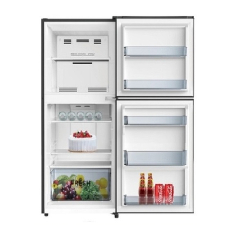
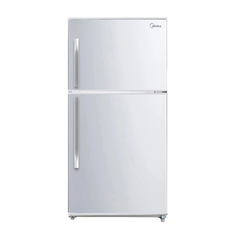
Midea SO-BD386WE-UT User manual

Service manual, 2016-12
1/ 42
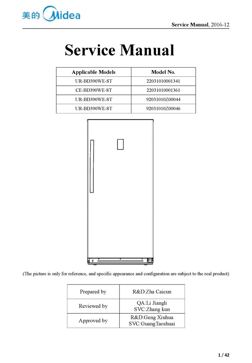
Service Manual
Applicable Models
Model No.
SO-BD386WE-UT
22031010000120
UL-BD386WE-SQ
22031010000112
UL-BD386WE-FQ
22031010000107
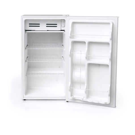
(The picture is only for reference, and specific appearance and configuration are subject to the real
product)
Prepared by
R&D:Zheng Qiang
Reviewed by
QA:Wang Tao
SVC:Zhang Kun
Approved by
R&D:Geng Xiuhua
SVC:Guang Taoshuai

Service manual, 2016-12
2/ 42
Important Safety Notice
The Maintenance Manual is only for the use of maintenance personnel with certain experience and background
in electrical, electronic and mechanical field.
Any attempt to repair main devices may lead to personal injury and property loss.
Manufacturers or distributors are not responsible for the content of the Manual and interpretation thereof.
Midea Refrigerators
Technical Maintenance Manual
Copyright @2016
All rights reserved. Replication of all or part of the Manual in any forms shall not be allowed without written
approval by the Overseas Sales Corporation of Midea Refrigerators.

Service manual, 2016-12
3/ 42
Contents
1.SAFETY WARNING CODE..................................................................................................................... 5
1.1WARNING FOR OPERATION SAFETY ...............................................................................................................5
1.2SAFETY INSTRUCTION FOR REFRIGERANT .....................................................................................................8
2.DESCRIPTION FOR PRODUCT FEATURES....................................................................................... 9
3.INSTALLATION AND COMMISSIONING...........................................................................................10
3.1HANDLING..................................................................................................................................................10
3.2DISASSEMBLY (NONE)................................................................................................................................10
3.3 INSTALLATION LOCATION...........................................................................................................................10
3.4LEVELING OF THE REFRIGERATOR ..............................................................................................................10
3.5CHANGE THE DOOR OPENING DIRECTION(NONE)........................................................................................11
3.6 INSTALLATION OF HANDLE.........................................................................................................................11
3.7 INSTALLATION OF DOOR LOCK(NONE)........................................................................................................12
3.8ADJUSTMENT TO LEVEL THE DOOR(NONE).................................................................................................12
3.9ADJUSTMENT TO SHELVES(NONE)..............................................................................................................12
4.TERMS ....................................................................................................................................................12
4.1 DEFINITION OF MODEL(NONE) .....................................................................................................12
4.2LOCATION OF NAMEPLATE ..........................................................................................................................12
5.PRODUCT SPECIFICATION ................................................................................................................13
5.1 TYPESPECIFICATION(NONE).......................................................................................................................13
5.2 ELECTRICAL PARAMETERS .........................................................................................................................13
5.3INSIDE TEMPERATURE.................................................................................................................................13
5.4DEFROSTING PARTS.....................................................................................................................................14
5.5CIRCUIT DIAGRAM ......................................................................................................................................14
6.INTERNALVIEWAND DIMENSION ..................................................................................................16
6.1MAIN PARTS AND THEIR NAMES ..................................................................................................................16
6.2EXTERNAL DIMENSION................................................................................................................................16
7.REFRIGERATING PIPING SYSTEM AND CIRCULATING ROUTE OF COOLING AIR.................................................19
7.1 REFRIGERATING PIPING SYSTEM.................................................................................................................19
7.2CIRCULATING ROUTE OF COOLING AIR ........................................................................................................20
8. DISMANTLING OF PARTS ..................................................................................................................21
8.1 PARTS ON THE DOOR...................................................................................................................................21
8.2PARTS INSIDE THE REFRIGERATOR...............................................................................................................21
8.3LIGHT SYSTEM............................................................................................................................................21
8.4AIR DUCT AND FAN MOTOR .........................................................................................................................22
8.5EVAPORATOR AND TEMPERATURE SENSING SYSTEM....................................................................................23
8.6COMPRESSOR CASE.....................................................................................................................................24

Service manual, 2016-12
4/ 42
8.7DISPLAY AND MAIN CONTROL PANEL ..........................................................................................................26
8.8 BAR COUNTER(NONE)................................................................................................................................26
8.9 WATER DISPENSER(NONE).........................................................................................................................26
8.10 ICE MAKER(NONE)...................................................................................................................................27
9. FUNCTION AND OPERATION............................................................................................................28
9.1 OPERATION PANEL .....................................................................................................................................28
9.2 BUTTON .....................................................................................................................................................28
9.3 DISPLAY SCREEN........................................................................................................................................28
9.4 DISPLAY.....................................................................................................................................................28
9.5 SETTING OF THE GEAR................................................................................................................................29
9.6 CONTROL OF STANDBY FUNCTION(NONE)..................................................................................................29
9.7 CONTROL OF ICE MAKER (NONE)...............................................................................................................29
9.8 FAULT CODE AND SOLUTIONS.....................................................................................................................29
9.9DEFROSTING FUNCTION ..............................................................................................................................30
9.10TEST MODE...............................................................................................................................................30
9.11SELF-DIAGNOSIS .......................................................................................................................................30
10.CIRCUIT DESCRIPTION.................................................................................................................................31
10.1 POWER SUPPLY ........................................................................................................................................31
10.2DOOR TRIP TEST CIRCUIT ..........................................................................................................................31
10.3TEMPERATURE TEST CIRCUIT ....................................................................................................................31
10.4FAN MOTOR CIRCUIT OF THE FREEZING CHAMBER.....................................................................................32
10.5REFRIGERATOR FAN MOTOR CIRCUIT (NONE)............................................................................................33
10.6CONDENSING FAN MOTOR CIRCUIT (NONE)...............................................................................................33
10.7DAMPER MOTOR CIRCUIT (NONE).............................................................................................................33
10.8RESISTANCE VALUE OF THE SENSOR (R/T) ................................................................................................33
11.TROUBLESHOOTING METHOD.......................................................................................................34
11.1 NO REFRIGERATION..................................................................................................................................34
11.2 COMPRESSOR FAILURE .............................................................................................................................35
11.3 DEFROSTING IS NOT WORKING .................................................................................................................36
11.4 FAN IN THE FREEZING CHAMBER IS ABNORMAL........................................................................................36
11.5 DAMPER IS ABNORMAL(NONE)................................................................................................................37
11.6 LIGHTS INSIDE THE REFRIGERATOR DON’T LIGHT UP ................................................................................37
12. FIGURES AND DETAILS OF REPAIR PARTS(DOCUMENTS ARE PROVIDED SEPARATELY)
.....................................................................................................................................................................37
12.1 FIGURE.....................................................................................................................................................37
12.2 LIST OF PARTS AND COMPONENTS ............................................................................................................37
13APPENDIX:...................................................................................................................................................37
13.1ELECTRICAL SCHEMATIC DIAGRAM..........................................................................................................37
13.2REFRIGERATOR MAINTENANCE TOOLING AND EQUIPMENT AND MATERIAL...............................................38
Service manual, 2016-12
5/ 42
1.Safety Warning Code
1.1Warning for operation safety

Service manual, 2016-12
6/ 42

Service manual, 2016-12
7/ 42

Service manual, 2016-12
8/ 42
1.2Safety instruction for refrigerant

Service manual, 2016-12
9/ 42
2.Description for product features
This product is provided with following features:
(The picture is only for reference, and specific appearance and configuration are subject to the real
product)
1)Full air-cooling and frost-free design
2)Electronic temperature control system with more accurate temperature control.
3)Open delay alarm function

Service manual, 2016-12
10 / 42
3.Installation and commissioning
3.1Handling
1) Protecttherefrigeratorinmovingit
Sameasshownasleftphoto,pleasemoveitbyhandcartwi
thcushion
2) Removeallpackingmaterialsandbottomcushion,then
moveintohouseforplacement
3) Aftermovingittoappropriatelocation,waitfor2hoursbe
forepoweron.
3.2Disassembly (None)
The refrigerator door needs to be dismantled if it cannot enter the room in the whole.
3.3 Installation location
Location that is easy for ventilation shall be
chosen to facilitate heat dissipation, enhance
its performance and reduce the energy
consumption.
3.4 Leveling of the refrigerator
If the refrigerator cannot be placed steadily,
adjust the footing to level it.

Service manual, 2016-12
11 / 42
3.5Change the door opening direction(None)
3.6 Installation of handle

Service manual, 2016-12
12 / 42
3.7 Installation of door lock(None)
3.8 Adjustment to level the door(None)
3.9 Adjustment to shelves(None)
4.Terms
4.1 Definition of model(None)
4.2Location of nameplate
(The picture is only for reference, and specific appearance and configuration are subject to the real
product)

Service manual, 2016-12
13 / 42
5.Product specification
5.1 typespecification(None)
5.2 Electrical parameters
Product Name
SO-BD386WE-UT
UL-BD386WE-SQ
UL-BD386WE-FQ
Product Code
22031010000120
22031010000112
22031010000107
Name
Item
Type
Specification
Specification
Specification
Compressor
Compressor
/
PE50H1F-4SVL
EE50H1C
HYE60Y42
Starter
PTC
8EA19C3/QP2-15/
QP2-15
QPE2-A4R7MD3
QP2-4R7
Overload protector
OLP
3TM166TF2/DRB
18T61A1
DRB31T61A1
DRB33S61A1
Winding resistance
of compressor wiring
terminal
Rmc:10-20Ω
Rsc:30-50Ω
Rms=Rmc+Rsc
Rmc:10-20Ω
Rsc:30-50Ω
Rms=Rmc+Rsc
Rmc:10~20Ω
Rsc:30~50Ω
Rms=Rmc+Rsc
Variable frequency
driver board
/
/
/
/
Motor
Fan motor of the
freezing chamber
DC12V/≤4W
DC12V/≤4W
DC12V/≤4W
Ventilation door of
the refrigerating
chamber
/
/
/
Condensation fan
/
/
/
Lights inside
the
refrigerator
Lights inside the
freezing chamber
240V/40W
125V /40W
125V /40W
Lights inside the
refrigerating
chamber
/
/
/
/
Switch of the
refrigerator door
mechanicals
witch
sector
sector
sector
5.3Inside temperature
Temperature tolerance ≤ 2 oC
Compartment
The highest (oC)
Lowest (oC)
Freezing
-24
-26
Refrigerating
/
/
Variable temperature
/
/

Service manual, 2016-12
14 / 42
5.4Defrosting parts
Defrosting period
Initial defrosting period
Normal defrosting period
Temperature is lower than 0oC
6~24 hours
Defrosting sensor
NTC
B3839
Thermal fuse
Can’t be restored
77℃
Defrosting heater in freezing chamber
Steel pipe
230V/180W
115V/180W
5.5Circuit diagram
SO-BD386WE-UT_22031010000120
UL-BD386WE-SQ_22031010000112(UL-BD386WE-FQ_22031010000107)

Service manual, 2016-12
15 / 42

Service manual, 2016-12
16 / 42
6.Internal view and dimension
6.1Main parts and their names
(The picture is only for reference, and specific appearance and configuration are subject to the real
product)
Freezing chamber
Refrigerator chamber
1.Air duct front plate
2.Steel wire storage rack(big)
3.Air duct assembly of freezer
4.Steel wire storage rack(small)
5.Steel wire drawer
6.Leveling feet
7.Freezer door tray
8.Reversible adjustable shelf
9.Refrigerator door tray
6.2External dimension
Front view
Side view

Service manual, 2016-12
17 / 42
Down view
Open Door
Maximum open angle of door(135o)

Service manual, 2016-12
18 / 42
(The picture is only for reference, and specific appearance and configuration are subject to the real
product)

Service manual, 2016-12
19 / 42
7.Refrigerating piping system and circulating route of cooling air
7.1 Refrigerating piping system
1Compressor→2Right condenser→3Anti-condensation tube→4Left condenser→5Dry
filter→6Capillary tube→7Evaporator→8Suction tube→1Compressor
(The picture is only for reference, and specific appearance and configuration are subject to the real
product)

Service manual, 2016-12
20 / 42
7.2Circulating route of cooling air
(The picture is only for reference, and specific appearance and configuration are subject to the real
product)
This manual suits for next models
8
Table of contents
Other Midea Refrigerator manuals

Midea
Midea MDRE353FGF Series User manual

Midea
Midea HD-423FWWD User manual

Midea
Midea CO1002 WHITE User manual

Midea
Midea HS-196L User manual

Midea
Midea HS-121LN User manual

Midea
Midea HS-507FWEN User manual

Midea
Midea MRB19B7AWW User manual

Midea
Midea SBS Series User manual

Midea
Midea MRQ23B4AST User manual

Midea
Midea TMF No Frost Series User manual

Midea
Midea HS-411S User manual

Midea
Midea MTM258W User manual

Midea
Midea MRT18S2ASS User manual

Midea
Midea COMBI Series User manual

Midea
Midea MB46W User manual

Midea
Midea TMF Series User manual

Midea
Midea WHD-774FW1 User manual

Midea
Midea UL-BCD283WE-DQ User manual

Midea
Midea SBS Series User manual

Midea
Midea MFD635S User manual