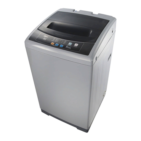
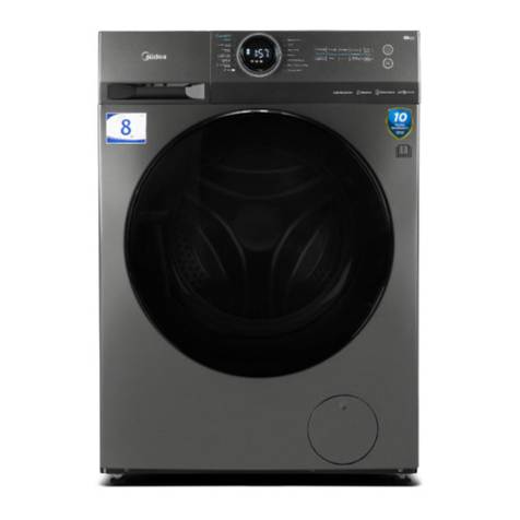
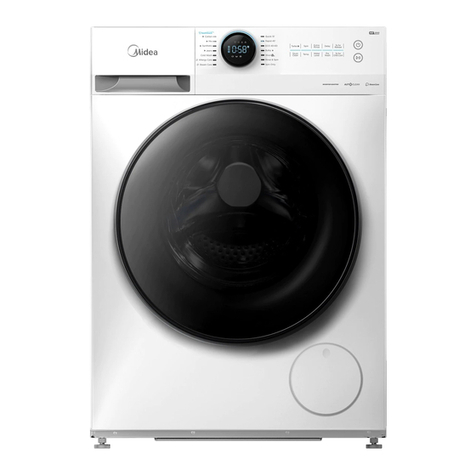
Midea RW145 User manual

Service Manual
Washing Machine
Model: E Products
Note:
Before service the unit, please read this manual first.
Contact with your service center if meet problem

1 PRECAUTION………………….………………..…………………………………………………. 3
1.1 Safety Precautions
1.2 Servicing Precaution
1.3 Cautions For Safety
2 FACTORY PATTEN DETECTION …………….………………………………………………. 7
3 UNPACKING WAYS OF MAIN PARTS……………………………………………………… 10
4 MALFUNCTIONS CODES AND EXPLANATIONS ……………………………………… 18
5 TROUBLESHOOTING …………………………………………………………………………… 20
5.1 Maintenance non-heating malfunction
5.2 Door non-locked & its maintenance
5.3 Door non-locked & its maintenance
5.4 Heating beyond the setting temperature its maintenance
5.5 Maintenance of non-drain or drain exceed the setting time
5.6 Water inlet overflow malfunction maintenance
5.7 Drum non-rotating malfunction maintenance
5.8 Maintenance water inlet and water outlet at the same time
6 CHECK POINT OF CIRCUIT …………………………………………………………………… 30
7 SERVICE TOOLS……..………………............................................................................... 31
8 APPENDIX………………………………………………………………………………………….. 32
Contents
2

1.3 CAUTIONS FOR SAFETY
•Please observe the following notes for safety.
•The symbols indicate as follows.
3
Symbol Meaning
WARNING
Indicates possibility of death or serious injury of a repair
technician and a person nearby through the misconducted
work , or of a user by a defect of the product after the work
performed by the technician.
CAUTION
Indicates possibility of injury or physical damages* of a
repair technician and a person nearby through the
misconducted work , or of a user by a defect of the product
after the work performed by the technician.
Symbol
Meaning
ELECTRIC SHOCK
Indicates a caution (including a warning).
Specific instruction is followed by a graphic or characters in
or near.
Symbol left warns an electric shock.
DO NOT DISASSEMBLE
Indicates prohibition (act must not be conducted).
Specific instruction is followed by a graphic or characters in
or near.
DO NOT Symbol left warns not to disassemble.
UNPLUG
Indicates forcing (act must be conducted).
Specific instruction is followed by a graphic or characters in
or near .
Symbol left warns to unplug the power cord.
* Means secondary damages of property, furniture , domestic animal and pet.
Symbol
Meaning
OUT OF CHILD
Advise the customer to keep children out of the work place.
Children may be injured with a tool or a disassembled part.
UNPLUG POWER
Unplug power cord for the work such as disassembling
which is not
unnecessary to power on . Do not hold the plug by a wet hand.
Failing to unplug may cause an electric shock.
USE REPAIR PARTS
Use the specified repair parts when repairing the product.
Otherwise , amalfunction or a defect may occur.
Also , a short circuit , ignition or other danger to the
customer may occur.
1 Precaution

4
WARNING
CHECK INSULATION
RESISTANCE
After repair, measure insulation resistance between the
charging part(power cord plug) and the non-charging
metallic part (ground) with an insulation resistance meter
(500V).The resistance shall be 10M or more.
Failing to check the insulation resistance may cause a short
circuit, electric shock or other diseases to the customer.
DO NOT MODIF
Do not modify the product.
An electric shock or ignition may occur.
DO NOT MODIFY
Only a repair technician can disassemble and repair.
An electric shock, ignition or malfunction may cause injury.
USE EXCLUSIVE
SOCKET
Use an exclusive 110 VAC/15 A socket for the washing
machine.
Use an exclusive 220VAC/17A socket for the washing
machine.
Otherwise , an electric shock or ignition may cause. Sharing
the same socket with other instrument causes heating of a
branch socket and result in a fire.
CONNECT
GROUNDING WIRE
Connect the grounding wire.
Failing to do so may cause an electric shock when a short
circuit occurs.
Consult an electric work shop or a sales shop.
DO NOT USE WET
PLACE
Do not install in a bath room or a place exposed to wind or
rain.
An electric shock or a short circuit may cause a fire.
DO NOT SPLASH
WATER
Do not pour or immerse electrical parts into water or liquid
solution.
An electric shock or ignition may occur.
REMOVE DUST
Wipe off dust adhered to the plug of power cord.
Dust may cause a fire.
AVOID
INFLAMMABLE
Do not put inflammable into the washing tub.
Do not put cloths stained with kerosene, gasoline, benzene,
thinner, alcohol, etc. lt may cause a fire or explosion.
1 Precaution

5
WARNING
DO NOT TOUCH
Do not touch the laundry before the spin basket stops
completely.
The laundry entangles your hand causing an injury even if
the basket rotates slowly. Pay special attention to children.
INSTALL
CAREFULLY
Ask an electric work shop to install the product.
Install the product securely and safely according to the
electrical equipment technical standard and the wiring
standard.
Incorrect work causes an electric shock and a fire.
DO NOT PULL
Do not pull the power cord when unplugging.
Hold the power plug to unplug.
An electric shock or short circuit may cause a fire.
DANGER HAND
Do not insert your hand under the washing machine during
operation.
There is a rotary part under the machine which may cause
an injury.
WATER LEAKAGE
Before starting washing, open the faucet and check water
supply hose joint which shall not be loosened for no water
leaks.
The loose screw or hose joint may cause water leakage
resulting in an unexpected damage.
1 Precaution

2 FACTORY PATTEN DETECTION
6
2. Service mode
2.1 Versions information checking
Rotate the nob to any program from “ON/OFF”, Press
the“L1“,“L3”,L1“,“L3”button in order in 10 seconds, then the door will be
locked(L5 turns on), L4 turns on. that means machine enters service testing mode.
Testing 01 ,and the abbreviation is T01. (note: All the lights in the bottom line show in
binary format. The L4 light means number 1, so as the T01. L3 light means number 2,
L2 means number 4, and L1 means number 8.) press L4 , L6 will turn on, and the lights
in bottom line show the project version; in binary format.
2.2 Display the error code mode
After entering service testing mode, press L1,until L3,L5 turn on. The others turn off.
That means T02,error mode.
1) Press L4 two times. Then the four lights in the bottom line shows the error code. if
L1 twinkles only, that means no error. You can check the others error codes ,according
to the Schedule of failure alarm
the machine runs The “K1” light display the error code is index(the index with1-10).
2) Press the “L1” changed into the error code with last time, there is display 10
times at most.
4) It can memory 10 error codes at most, the two error connection only record one time
5) Clear all the error codes : press L2+L3 3seconds, all error codes after hearing buzzing.
6) Press L4 again, and you will exit error mode.
L1
Prewash
L2
Extra Rinse
L3
No Spin
L4
Pause
Start
L5
Door Lock
L6
Child Lock

7
2.3 The user interface testing(T04)
1. After entering service testing mode, press L1,untill L2 turns on, the others turn off,
that means T04.
2. Press L4 two times.
3. Display project number about 2 seconds, L6 will turn on simultaneously. And the
project number will be showed by the four lights in the bottom in binary format.
4. Display program vision number about 2 seconds, L6 will turn off simultaneously.
And the program vision number will also be showed in binary format.
5. Then the four lights will turn on one by one ,from L1 to L4.
6. Press L2,enter knob test . Rotate the knob to different position, and the led lights
(L1-L6) will turn on in binary fomat.L6 means number 16,L4 means number 8,L2
means number 2, and L1 is number1 .
7. Finally, press L4 to exit the user interface testing.
2.4 Water level checking(Drain pump checking, water switch checking, inlet valve
checking)
2.4-1 Drain pump checking(T05)
1. After entering service testing mode, press L1,untill L2,L4 turns on, the others turn
off, that means T05
2. Press L4 two times , then L3 turns on, pump testing starts. If all the water drain
out,L1—L4 turns off. If it can not drain water out ,L3 will twinkle all the time. Then you
should confirm the connect to the pump.
3. Finally, press L4 to exit drain pump checking.
2.4-2 Water switch checking(T06)
1. After entering service testing mode, press L1,untill L2,L3 turns on, the others turn
off, that means T06
2. Press L4 two times , then L1 turns on, water begin fill the machine from the water
inlet to the level for the main wash.
3. Press L4 to exit water switch checking. And it will drain all the water out of the
machine, finally.
2.4-3 Inlet valve checking (T08)
1. After entering service testing mode, press L1,untill L1 turns on, the others turn off,
that means T08
2. Press L4 two times , L1 and L2 turn on.
3. Press L1,L2 turns on, pre-wash inlet valve begin to work for 10 seconds.
4. Press L1, L1 and L2 turn on, main inlet valve and pre-wash inlet valve work
simultaneously until the water in the machine reaches the set level. If it can not reach
the level in 5 minutes. Water injection will also stop.
5. Press L4 to exit Inlet valve checking . And it will drain all the water out of the
machine, finally.
2.5 spin velocity checking(T10)
1. After entering service testing mode, press L1,untill L1,L3 turns on, the others turn
off, that means T10
2. Press L4 two times , L3and L4 turn on. Then basket assembly spins at the velocity
of 45 r/m, rotates clockwise 15 seconds, stop 10 seconds, and rotates
anticlockwise 15 seconds, stop 10 seconds again, and that cycle repeats.
3. Press L4 to exit spin velocity checking mode. And motor stops.
2 FACTORY PATTEN DETECTION
3. UNPACKING WAYS OF MAIN PARTS
1. Undo the back cover
2. Undo top cover
3. Undo the control panel
4. Undo the lower panel
5. Undo the door lock
6. Undo the front plate
7. Undo the facade counterweight
8. Undo the gasket
9. Undo the PCB panel
10. Undo the detergent box
11. Undo the inlet valve
12. Undo the pressure
13. Undo the pulley
14. Undo the absorber pin
15. Undo the filter
16. Undo the drain pump
17. Undo the heater
18. Undo the NTC
19. Undo the door glass
20. Undo the panel support
21. Undo the drum tub assembly
22. Undo the absorber
23. Undo the motor
3 UNPACKING WAYS OF MAIN PARTS
8

999
Operation Picture
1
.Undo the back cover
Undo four screws fit
between back plate and
cabinet, and then pull out.
2
.Undo the top cover
I.Undo 2 screws fit back
Cabinet.
II.Push back the top cover
15mm until it leaves away
from the control
panel,
and then take it down.
3
.Undo the control panel
I.Departing the top cover
II.Draw out the detergent
drawer.
III.Loosen two screws fit
on the control panel .
IV.Loosen two screws fit
on the control panel.
V.Take out the control
Panel inclined from the
panel .
3 UNPACKING WAYS OF MAIN PARTS

1010
4
.Undo the lower panel
I.Open the filter
cover,
release the screw on
the
lower panel.
II.Turn the washing
machin back at an angle,
pinch the clasp ,and push
it out.
5
. Undo the door lock
I.Open the door of
washing machine.
II.Take the outer gasket
Take the outer gasket
III.Remove two screws on
the door lock, and take
down the door lock.
IV.Take out the door lock
and draw out the plug.
6
.Undo the front plate
I.Remove the lower cover.
II.Undo five screws in
front plate
III.Put the front plate up to
the clasp of the front plate
away from the loading
holder, and then take off
the front plate.
7.
Undo the facade
counterweight
I.Undo the front plate
II.Remove six screws pull
out the facade
counterweight.
3 UNPACKING WAYS OF MAIN PARTS

11
3 UNPACKING WAYS OF MAIN PARTS
1111
8. Undo the gasket
I.Undo the top cover,
control panel, lower
cover, machine door and
the front plate.
II.Remove the outer
gasket
clamp between the door
seal and the front plate.
III.Loosen the inner gasket
clamp between the door
seal and the front of the
outer tub.
9. Undo the PCB panel
Undo the top cover and
control panel
10. Undo the detergent box
I.Undo the top cover and
the control pane
II.Release the hose clamp
and pull out the inlet hose.
III.Release the hose clamp
and pull out the detergent
box hose, and then take
out the detergent box.
11. Undo the inlet valve
I.Remove the top cover
II.Undo 2 screws between
cabinet and inlet valve.
III.Release the clamp fixing
the inlet valve and the
inlet hose, and then pull
out the inlet hose.
IV.Take out the inlet
valve

121212
12
. Undo the pressure switch
I.Undo the top cover
II.Pull out the plugs on the
pressure switch.
II. Loosen the screw
of
pressure
switch
III. Disconnect the
pressure
switch
from air pipe.
13
.Undo the pulley
I.Undo the back cover
II.Rotate the pulley and at
the same time pull out the
belt.
II.Remove the screw on
the
pulley and then take
down
the pulley.
14
.Undo the upper
counterweight
I. Undo the top cover
II. Remove three screws fit
on the upper
counterweight and then
pull out the upper
counterweight.
15
. Undo the absorber pin
I.Undo the front plate
II.Use pliers to pinch the
absorber pin’s
protuberance, and knock
the absorber pin out from
back lightly; in the same
way, remove the other
one.
3 UNPACKING WAYS OF MAIN PARTS

131313
16
.Undo the filter
Open the filter cover.
Rotate the filter knob
anticlockwise, and then
pull out the filter.
17. Undo the drain pump
I.Undo the top cover,
control panel, lower cover
and front plate.
II.Nip out clamp between
drain hose and the drain
pump, and then pullout
the drain hose.
III.Loosen
the screws fitted
on the drain pump, and
then pull out the drain
pump.
18
.Undo the heater
I.Under the top cover,
II.control panel lower
cover and front plate.
III.Pull out the heater plug
.
3 UNPACKING WAYS OF MAIN PARTS

141414
19
. Undo the NTC
I.Undo the top cover,
control panel, lower
cover
and front plate.
II.Undo the NTC with
special tools.
20
.Undo the door glass
I. Open the door, remove
two screws fixing the
hinge and front plate,
and
then remove the door.
II. Remove six screws on
the inner door.
III. Remove the outer
door
and the inner door
with
special tool.
21
.Undo the panel support
I. Undo the top cover
II.Undo the control panel.
III.Remove two screws
fixing the panel support,
and then remove it.
22.Undo
the drum tub
assembly
I.Remove the motor in
II.Pull out the heater.
III.Remove the belt.
VI.Remove the screws
fixing the pulley, and then
take out the pulley.
V.Remove the screws
fixing
the front and rear tub,
and
then remove the tub.
VI.Remove the inner drum
kit.
3 UNPACKING WAYS OF MAIN PARTS

151515
23
.Undo the absorber
I.Lift out the outer tub kit.
II.Undo the absorber pin
between absorber and
rear tub, remove the
absorber.
24
.Undo the motor
I.First let the machine lie
down on the back and
then pullout the motor
wire and grounding wire.
II.Use spanner to remove
the motor screw, and lift
up the motor with the
other hand in case of
falling to the drain pump
III.After two screws are
removed, change the
motor. First support it to
clasp the correct position,
then install the screws.
3 UNPACKING WAYS OF MAIN PARTS

16
Malfunction
code Reason Description Solution
E10
Inlet water
overtime
The water level
doesn’t changed in 3
minutes during filling
the water.
Open the water tap, to check if the
inlet hose is squashed or kinked,
check the filter in the inlet valve is
blocked or not; check if the water
pressure is too low.
E12
Overflow
The water level is
higher than the
overflow water level.
Check the water inlet valve, Valve fail
E20
Fault connection
of the drain pump
The water level
doesn’t changed in 3
minutes during drain
the water.
Check the drain pump.
Check the filter of the drain pump
to prevent jam.
Check the drain hose to prevent jam.
E21
Overtime 3min
of the drainage
The water level.
Overtime draining
E30
The door has not
been closed over
3 times
Fail to lock the door
lock for 6 times when
the PCB ties to lock the
door lock after you
press the Start keys.
Check the door hook and the door
lock to get correct location.
E31
Don’t unlock the
door lock
Fail to unlock the door
lock 6 times
Check the door Lock
E33
Water level sensor
fail
The frequency of the
water level sensor is
out of the spec.
Check the water level sensor
E34
Temperature
sensor fail
The temperature
sensor(NET) get broken
Check the PCB and the motor
E60
The motor don’t
drive
The motor don’t drive
for
5 times
Water temperature sensor
cutting
-
out
Check the PCB and the motor
Check the motor communicate
wire
E61
The speed don’t
transmit signal
The PCB can’t get
speed transmit signal
when the motor drive
Check the speed transmit line of
the motor to prevent fall
of
Check the PCB and the motor
Check the motor communicate
wire
4 MALFUNCTION CODES AND EXPLANATIONS
Schedule of failure alarm

17
Malfunction
code Reason Description Solution
E62
The speed
don’t transmit
signal
abnormality
Triac
get broken
Check the speed transmit line
of the motor to prevent fall of
Check the PCB and the motor
Check the motor communicate
wire
E70
The button get
stuck when
press
it over 10
second
The Power
button
lodge in the panel
Check the button install
and
control
4 MALFUNCTION CODES AND EXPLANATIONS

5 TROUBLESHOOTING
18
Fault tree
1. Maintenance non-heating malfunction
Whether the pressure
switch is well or not
well or not
Change the control
panel
Whether the
connect is well well
heating Reliable connection
Whether NTC is
short or open
circuit Change NTC
Whether to set up
non-heating Choosing new heating
temperature
Non-heating
Change the heater
Whether the heater
is well
Y
Y
Y
Y
Y
N
N
Y
N
N

19
2. Door non-locked & its maintenance
Whether push the
start /pause
button
Whether the harness
connection between the
door lock and the main
board is well
Whether the voltage open
between harness 1 harness 3
is about 220vand circuit
The door lock is
invalid and should be
replaced
Whether the door
is closed correctly
Close the door
correctly
Door non-locked
Change the heater
Change the
control panel
Push the start button
to start the program
N
N
N
N
Y
Y
Y
Y
Y
5 TROUBLESHOOTING

3. No water inlet or water inlet overtime
Connect
connections
Whether press
start/pause button
after choosing the
program
Change main
board
No water inlet or
water inlet
overtime
Change the
pressure switch
Push start/pause
button
Change the inlet valve
Whether the door
is closed correctly
Whether door lock 3
and 2 is connected
correctly
Whether the
electromagnetic valve
buzz
Whether the connections
of inlet valve is well
Whether the inlet
valve coil is well
Whether the connection
of pressure switch is well
Door lock is invalid
and should be
replaced
Whether the voltage
between door lock 1
and is220V
Whether the tap is
opened
Whether the inlet
pipe is fold or the
water is cut off
Whether the inlet filter
net is blocked
Whether the
pressure switch is
well
Change the control
panel
Whether the
connection is well
Cleaning with
brush
Y
Y
YYY
Y
Y
N
Y
Y
N
N
N
N
N
N
N
5 TROUBLESHOOTING
20
Table of contents
Other Midea Washer manuals

Midea
Midea MT1250G User manual

Midea
Midea MF200W100WB Series User manual

Midea
Midea MLV45N1BWWC Manual

Midea
Midea MFL80-ES1200 User manual

Midea
Midea MF710W User manual

Midea
Midea MFC80-JS1403B/C14E-AU User manual

Midea
Midea MTWM80 User manual

Midea
Midea MAC160-S2802TPS/FM User manual

Midea
Midea MF200W80B/W-MV User manual

Midea
Midea MLV41N1AWW User manual