1. PRECAUTION
When performing troubleshooting and part replacement during servicing, note the
following safety precautions:
1-1. Safety Precautions
1-1-1. Use Genuine Parts
The components of the washing machine have safety features such as non-combustibility
and voltage withstanding. Therefore, always use the same part as suggested by the maker.
In particular, be sure to use only designated parts in case of major safety parts identified
by the marker.
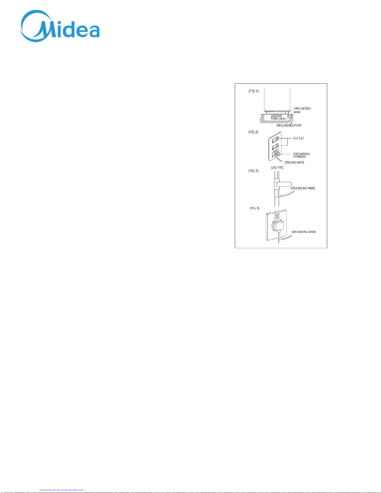
1-1-2. Grounding
Connect the grounding wire to the shell plate, and bury it under at least 25cm of earth :
alternatively, connect the ground wire to the appropriate pin on a properly grounded
power receptacle. Never connect the wire to a telephone line, lightning rod, or gas pipe.
1-2. Servicing Precautions
1-2-1. Observe Warnings
Be sure to follow special warning and precautions that are described on part labels and in
the owner's manual.
1-2-2. Parts Assembly and Wiring
Be sure to use insulation material (such as tube and tape). And be sure to restore all parts
and wires to their original position. Take special care to avoid contact with sharp edges.
1-2-3. Perform Safety Checks after Servicing
After servicing, check to see that the screws, parts, and wiring are restored to their
original positions, and check the insulation between the external metals and the socket
plug. In addition, place the washing machine in a level position (less than 1(one) degree)
to prevent vibration and noise during operations.
1-2-4. Insulation Checks
Pull out the plug from the power receptacle, pour water into the spin tub, and then set
the timer. Check to see that the resistance insulation between the terminals of the plug
and the externally exposed metal is greater than 1M• .
Note :When it is impossible to perform insulation check with a 500V insulation
resistance tester, use other testers for inspection.
1-1


 User manual")