Small Battery Box Instructions
Rev: A Page 5 of 6
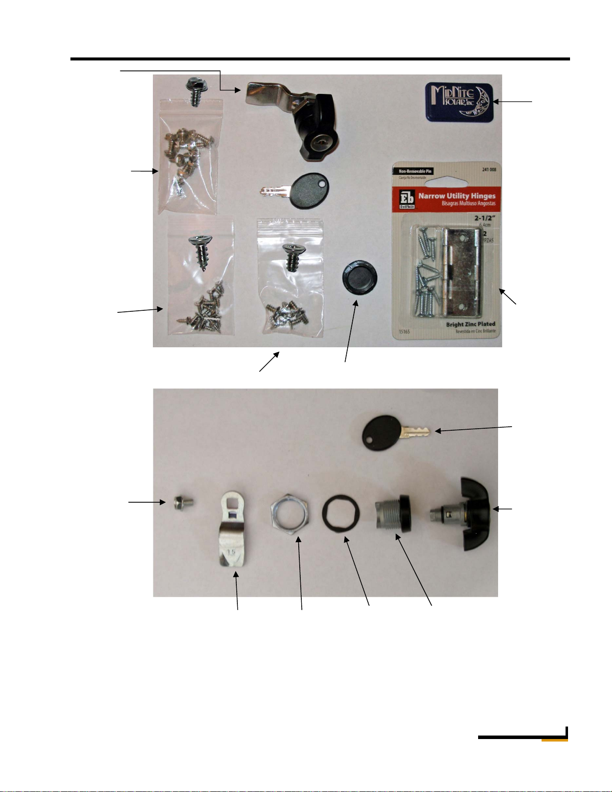
Step 5
Install lock. The lock will require disassembly in
order to feed it through the hole and slot. The
handle, lock body and washer go in from the front.
Position the lock body such that the cutout faces
towards the upper left as viewed from the front.
Secure lock body with the nut provided from the
back. Position the tab on the back of the lock and
tighten screw.
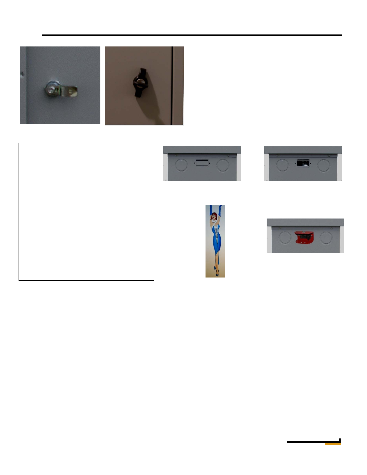
Note: Unit is locked when the tab is up (behind
shelf
.
Lock viewed from inside Lock viewed from outside
Optional DC Disconnect installation.
Many Jurisdictions are beginning to require
DC disconnects as part of the installation.
A double knockout is provided on the side
of the battery box to satisfy this
requirement.
Important! You must use sealed AGM or
Gel batteries when installing a circuit
breaker / DC disconnect in the cabinet.
Circuit breakers make sparks and vented
batteries cannot be in the same cabinet with
any device that makes arcs and sparks. The
circuit breaker must be installed in the
positive leg. Do not install in the negative
leg.
Battery box with no
breaker. Battery box with 125 amp
DC breaker. Remove only
the inner knockout
Battery box with 250 amp DC
breaker and optional protector.
Remove entire knockout.
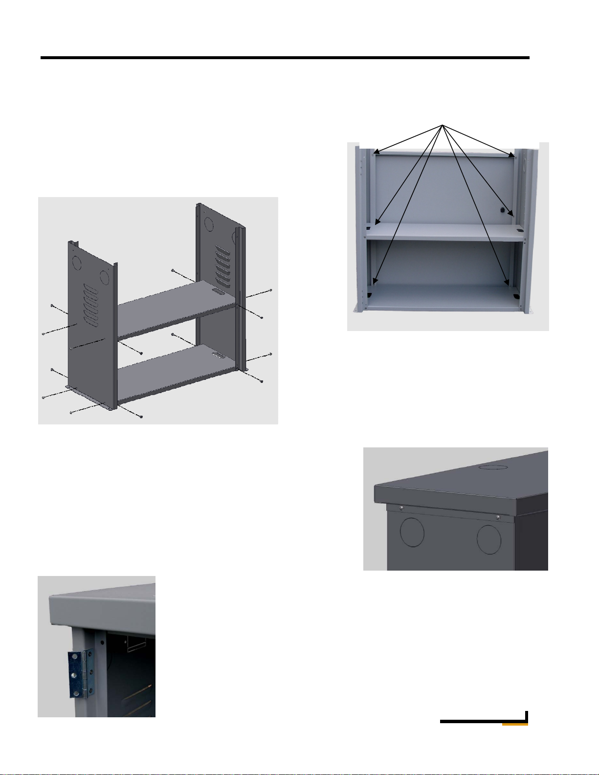
You may want to bolt the enclosure down using the .265” diameter holes on the bottom side flanges. You can
additionally drill holes through the back panel and bolt to a wall behind the enclosure to help make it earthquake
proof.
If two enclosures are required, they can easily be stacked horizontally. There are two sets of 2” knockouts on each
end plate that will accommodate running cables through a 6” long 2” diameter nipple. If stacking vertical, place a
¾” thick piece of wood inside the top cover of the lower enclosure on each end for added strength. This will keep
the lower cabinet from being crushed from the added weight. The upper enclosure should be bolted through the
back to a wall.
Slots are provided at the ends of the shelves for strapping batteries to the shelves. You will need to run strapping
for the bottom shelf prior to final positioning of the enclosure. Strapping is not supplied as part of the MNBE-A
kit.
The enclosure is set up to use sealed batteries as is. If installing flooded batteries, you may need to add venting
and spill trays. These items are not supplied by MidNite Solar.
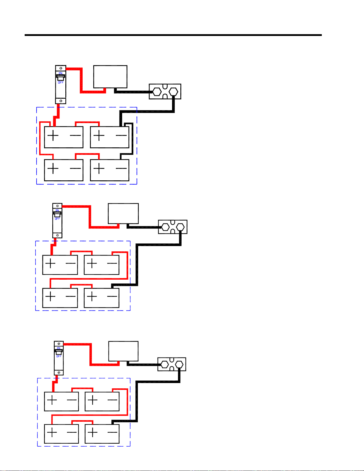
Always use caution when hooking up batteries. They can be very dangerous. Do not wear rings or watches. Pay
close attention to the order of cable installation. For instance if four 12V batteries are to be configured as a 24
volt bank, the batteries will be more safe to work around if the series connecting jumpers are installed after all
other connections have been made.
Note: Battery banks below 50 volts are not required to be grounded per the NEC.


 user manual")